Investigation on Broadening Compressor Surge Margin by Using Active Magnetic Bearing
←
→
Page content transcription
If your browser does not render page correctly, please read the page content below
Hindawi
Shock and Vibration
Volume 2022, Article ID 1139648, 13 pages
https://doi.org/10.1155/2022/1139648

Research Article
Investigation on Broadening Compressor Surge Margin by Using
Active Magnetic Bearing

 Yingzhe Lin ,1,2 Gen Bai ,2 Yunkai Huang ,1 Jin Zhou ,3 Xudong Guan ,4
 and Jiyong Dong 2
 1
 School of Electrical Engineering, Southeast University, Nanjing, China
 2
 Nanjing CIGU Limited Corporation, Nanjing, China
 3
 College of Mechanical and Electrical Engineering, Nanjing University of Aeronautics and Astronautics (NUAA),
 Nanjing 210016, China
 4
 School of Mechanical Engineering and Rail Transit, Changzhou University, Changzhou 213164, China

 Correspondence should be addressed to Yingzhe Lin; lyz@cigu.org.cn

 Received 15 September 2021; Revised 29 January 2022; Accepted 1 February 2022; Published 18 February 2022

 Academic Editor: Antonio Giuffrida

 Copyright © 2022 Yingzhe Lin et al. This is an open access article distributed under the Creative Commons Attribution License,
 which permits unrestricted use, distribution, and reproduction in any medium, provided the original work is properly cited.
 The impeller design usually expects to achieve high efficiency and a wide working range while they are influenced by tip clearance in
 different ways. In this study, a blower with a controllable magnetic suspension bearing was studied. The magnetic bearing enables the
 impeller to adjust the tip clearance during operation to optimize the efficiency of the blower at the design point and significantly
 expand the surge margin when it deviates from the design point. The clearance ratio (CR) is defined as the ratio of tip clearance over
 impeller outlet width. The computational fluid dynamics (CFD) method is used to study the performance of a centrifugal impeller
 under CR � 2.61%∼7.83% and verified by experiments. The results show that the pressure ratio and efficiency of the impeller at the
 design point decreased linearly with the increase of the gap. For each 1% increment in CR, the pressure ratio reduces by 0.02 and the
 polytropic compression efficiency declines by 0.5%. Conversely, the surge margin increases with the expansion of CR. For every 1%
 rise in CR, the surge margin would improve by 7.8%. A control method of changing the reference suspension position according to
 the optimal efficiency fitting model is proposed. It realizes the real-time control of the axial suspension position of the impeller
 according to the changes of pressure and flow rate signals to obtain the optimal work efficiency with a broad surge margin.
 Experimental results show that using an impeller equipped with a controllable magnetic suspension bearing could minimize the gap
 stably in the nonsurge area to obtain high efficiency, and when necessary, it could enlarge the gap to meet the low flow rate condition.

1. Introduction Senoo [1, 2] proposed a prediction model for the
 clearance loss and conducted experimental verification.
Maglev technology in recent years has brought great innovation Their results showed that the tip clearance loss is basically
for the industry compressor. However, limited by the strength proportional to the clearance ratio (when the clearance ratio
of the material, high-speed impellers are usually unshrouded is less than 0.1). LIU [3] explored the performance of Eckardt
which leaves a gap between the top of the blade and the side of impellers under three different gap values through nu-
the cover. For safety reasons, the gap cannot be diminished and merical simulation and experiments. In summary, the tip
the leakage flow caused by the tip gap will affect the efficiency of clearance is inversely correlated with the efficiency and
the impeller, pressure rise, surge margin, etc. Unlike the tra- pressure ratio of the impeller. The smaller the clearance is,
ditional blower, the controllable magnetic bearing can adjust the higher the efficiency of the impeller could achieve.
the blade tip clearance within a certain range so that the Surge is an inevitable problem in turbomachinery.
magnetic levitation impeller can theoretically achieve better Galindo et al. [4] explored the influence of different gaps
performance in both efficiency and surge margin. near the surge condition. Increasing the tip clearance allows
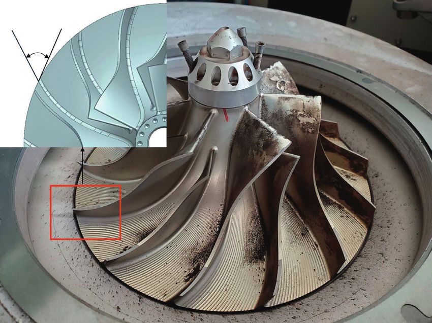
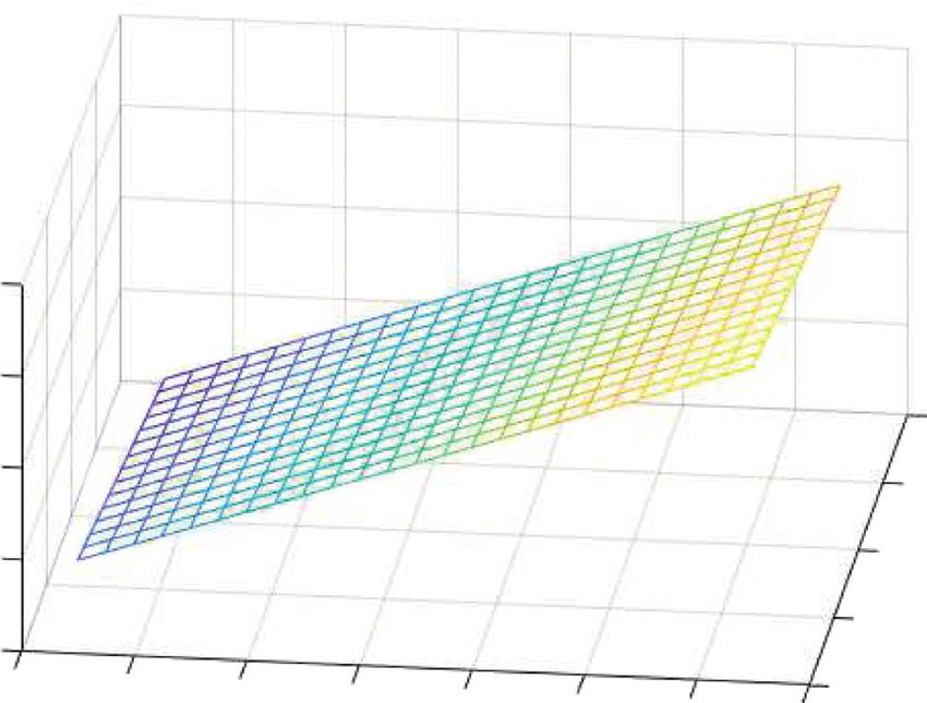
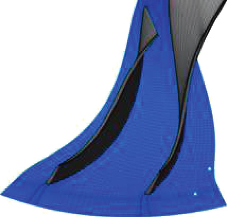
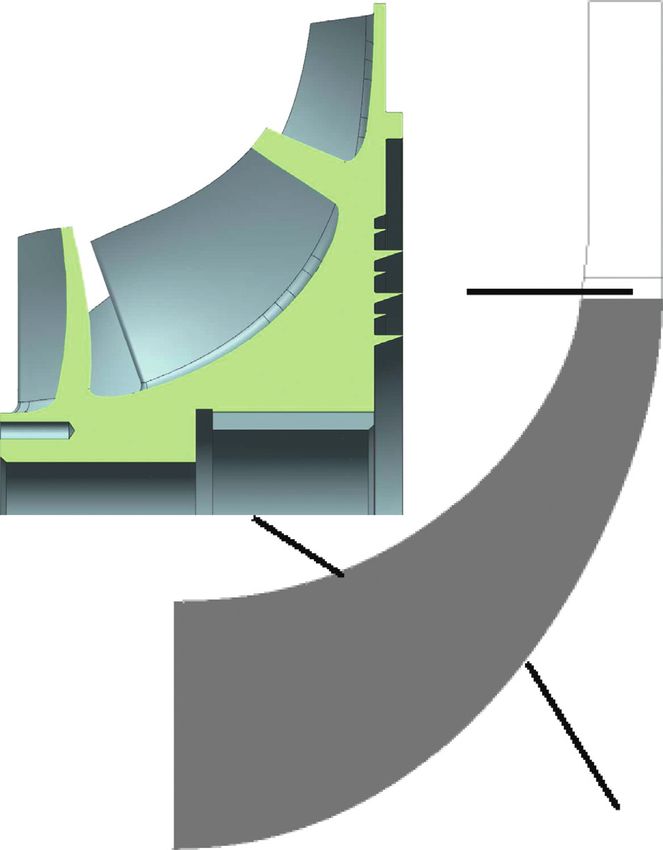
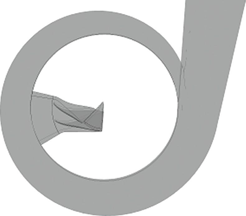
2 Shock and Vibration

a part of the gas to flow back to the inlet through the the control law of the gap value with respect to the flow rate
clearance, which increases the inlet flow and broadens the and pressure. Finally, the control method proposed in this
surge margin. Hewkin-Smith et al. [5] studied the role of paper to change the axial suspension position of the impeller
axial flow blade tip clearance in the pulse-like rotating stall. is used to achieve the balance between efficiency and surge
An axial compressor was studied and showed that the surge margin. Then, the feasibility of the proposed control method
margin increased when CR increased from 0% to 0.5%. is verified through experiments.
There are other ways to broaden compressor surge margin
which includes self-adaptive casing [6] and variable vanes 2. The Study Models
[7]. However, they require extra components and very
complicated structure which make them uneconomical for The case studied in this paper is a commercial compressor. Its
industry applications. main flow components include a backward curved impeller
 For magnetic levitation blowers, real-time gap adjust- with splitter blades, a vaneless diffuser, and a volute. Its design
ment can be achieved through active control, that is, keeping specific speed is 0.793 and maximum pressure ratio and
a small gap at the design point to obtain high performance maximum flow rate are 2.1 and 1.1 kg/s, respectively. The
and increasing the tip gap to expand the surge margin when designed static installation gap is 0.4 mm and the meridian
it deviates from the operating point [8]. In this way, it grants width of the vaneless diffuser with the pinch is 10.37 mm. See
the impeller high performance and wide working range Figure 1 and Table 1, for detailed geometric parameters.
simultaneously. Sanadgol and Maslen [9] realized the
control of the axial clearance of the impeller by adjusting the
axial active magnetic bearing (AMB) system. Yoon et al. 3. The Correlation between Surge Margin and
[10–12] used axial AMB to adjust the axial clearance of the Tip Clearance
compressor impeller based on the magnetic levitation
compressor test bench to achieve surge control. Aiming at 3.1. The CFD Study. The expression of surge margin S [20]
the surge problem of magnetic levitation compressors, Tang and clearance ratio (CR) are listed below:
et al. [13] designed feedback control strategies based on mass
 πs /ms
flow rate and output pressure, respectively. The simulation S � − 1 × 100%,
results showed that the adopted control strategy could ef- πd /md
 (1)
fectively expand the stable operation range of the com- c
pressor. Guan et al. [14] combined the magnetic levitation CR � × 100%,
 b
compressor model and the magnetic bearing rotor test bench
to obtain a semiphysical simulation surge control platform where πs is the pressure ratio at surge point, ms is the surge
and verified the simulation surge control effect under dif- flow rate, πd is the pressure ratio at design point, and md
ferent speeds and reference adjustment trajectories. Sun is the design flow rate. The CR (clearance ratio) is defined as
et al. [15] proposed an online surge detection method by the ratio of tip clearance c over blade outlet width b.
monitoring the axial displacement of the rotor. Ma et al. To obtain the relationship between surge margin S and
[16, 17] studied the surge suppression technology of the CR, the performance maps of the compressor were calcu-
AMB system. The rotor was stabilized under surge condition lated by CFD, as shown in Figure 2. Besides the pressure
by using the active-disturbance-rejection controller. Bon- ratio, the polytropic efficiency obtained from CFD is also
fitto et al. [18, 19] studied the offset-free model predictive plotted to compare with the experimental data.
control for AMBs and cone-shaped AMBs. This method not The commercial CFD software CFX was used to simulate
only takes full advantage of the superiorities of classical the flow field of the impeller, the vaneless diffuser, and the
model predictive control in terms of stability and control volute. To reduce the demand for computing resources, the
performance but also overcomes the influence of model impeller and diffuser adopt a single-channel periodic boundary
mismatch on reference tracking. In conclusion, the idea that condition. The frozen rotor model was used to connect the
suppressing compressor surge by adjusting tip clearance in rotating and stationary parts. The impeller was divided by
blower equipped with the AMB system is not new. However, structural grids with 15 layers of grids in the blade tip gap along
most of the previous studies are only simulation analysis and the blade height direction to capture the gap flow. The volute
their tip control models are too complicated to execute on was generated by a nonstructural grid and connected with the
industry application. vaneless diffuser by the frozen rotor model.
 In this article, the performance of a commercial mag- Numerical simulations calculated the performance map
netic levitation blower under the control of axial magnetic with CR which varied from 2.61% to 7.83%. Besides, the
bearings at different tip clearances and different speeds is performance maps when CR was 2.61%, 4.35%, and 6.09%
studied through experiments and numerical simulations. were verified by experiments.
First, the performance maps of the impeller under different In CFD study, the surge point was determined by
clearances are obtained by the numerical simulation method gradually reducing the outlet flow at the same speed. When
and verified by experiments. Secondly, according to the the outlet pressure no longer increased with the decrease of
experimental data, the minimum gap value under different the flow or the calculation showed that the outlet pressure
flow rates and pressures in the near-surge area is deter- did not converge over iterations, the point was considered to
mined. The first-order linear regression is adopted to find be surge.
Shock and Vibration 3

 ⑨ ①
 ⑧

 ③ ⑥ ⑦

 ⑤

 Hub

 ④

 (a) (b)

 Figure 1: Test impeller. (a) Meridional sketch. (b) Test prototype.

 Table 1: Geometrical parameters.
 Impeller Diffuser
(1) Number of blades 14 (7) Pinch out radius 112.125 mm
(2) Blade backswept angle 38.5° (8) Constant height 10.37 mm
(3) Exit radius 97.5 mm (9) Exit radius 170 mm
(4) Inlet hub radius 20.3 mm
(5) Inlet shroud radius 55 mm
(6) Exit blade height 11.52 mm

 (a) (b)

 Figure 2: Computational mesh of the impeller and the entire model. (a) Impeller single-channel mesh. (b) The overall CFD model.
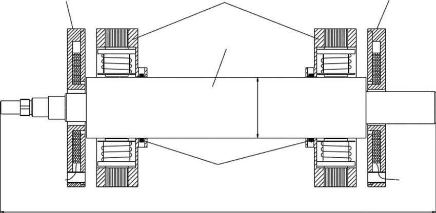
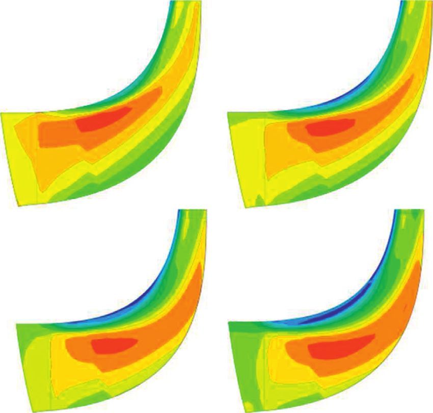
4 Shock and Vibration

 Figure 3 shows the performance maps of the impeller Based on the data of Table 2, the two-region control law
obtained through CFD in all operating conditions and the which keeps constant clearance at normal flow rate and
trend of pressure and efficiency at the design point as the CR adjust clearance at near-surge flow rate is plotted in Figure 6.
increases. Generally speaking, as the CR increases, the According to the data in Table 2, the linear regression
pressure ratio over the flow rate curve moves to the lower left equation is obtained; then, the gap value C � f(P, Q), where Q
and the compression efficiency declines. In the studied CR is the volume flow rate and P represents pressure rise:
range, the pressure ratio at different speeds drops with the
 C � −0.04051Q − 0.01713P + 3.7341. (2)
rise of CR at different speeds. At 100% speed, the pressure
ratio drops by about 0.02 for every 1% increase in CR; at 90% The regression error of the equation is shown in Table 3.
speed, it decreases by 0.011; at 80% speed, it declines by It can be seen that the maximum error of the first-order
0.0098. The decrease rates of efficiency with increasing CR at linear regression is 0.0293 mm.
different speeds are relatively close. For every 1% increase in Therefore, at the speed of 32000 r/min, the optimal
CR, the efficiency decreases by about 0.5%. clearance could be calculated through equation (3) as given
 below:
3.2. The Tip Clearance Effects on Surge Margin. By definition −0.04051 × Q − 0.01713 × P + 3.7341, Q < 45
 C(P, Q) � , (3)
of S, Figure 4 shows the relationship between surge margin 0.3, Q ≥ 45
and CR. The design point flow rate and pressure ratio are
1.1 kg/s and 1.905 individually. The surge margin at different where 0.3 mm is the minimum clearance that the AMB
speeds all increase with the rise of CR and alter approxi- system allowed.
mately linear. The surge margin rises from 26% to 59% as CR
varies from 0.026 to 0.07 at 32000 r/min. In addition, 4. The AMB Control System
compared with the decrease in efficiency, the surge margin
increases faster with the increase of CR. For every 1% in- The basic dimension and assembly relationship of the rotor
crease in CR, the surge margin will increase by about 7.8%. are shown in Figure 7. Each radial magnetic bearing is
 Figure 5 shows the meridional velocity contour under equipped with a displacement sensor. The detailed infor-
near-surge conditions with different CR. It can be seen that, mation of the AMB is listed in Table 4. The mass of the rotor
as CR increases, the low-velocity zone at the shroud side and impeller is 8.7 kg and 0.91 kg, respectively.
gradually increases and the affected area spreads from the The schematic diagram of each component of the
rear to the inlet. The gap flow under the large CR squeezes magnetic bearing system and its working principle is shown
the separation at the leading edge due to the reduced flow in Figure 8. It is mainly consisted of a controller, a power
rate so that the impeller can work at a lower flow rate. In amplifier, magnetic bearings, sensors, and the controlled
addition, the larger gap also allows the compressed high- object. In an ideal situation without external interference,
energy gas in the rear section to reinject to the front edge to the resultant electromagnetic force generated by the current
increase the energy of the inlet airflow and broaden the surge of the winding in the magnetic suspension bearing is equal to
margin. the gravity of the controlled object. Thus, stable suspension
 can be achieved without control. However, in the actual
 magnetic levitation system, the open-loop magnetic levita-
3.3. Clearance Control Model. Following the preceding tion system is unstable due to the negative displacement
discussion, increasing the tip clearance can broaden the stiffness of the electromagnetic force, so closed-loop control
surge margin, but at the same time, it will deteriorate the is required. Specifically, when the rotor is disturbed by the
efficiency. Usually, when the machine is running, it is outside disturbance, it will deviate from the original stable
expected that the efficiency is as high as possible while suspension position. The system detects the offset of the
adapting to different working loads. Based on this, a controlled object through the displacement sensor and feeds
clearance control method is proposed that when the it back to the controller. The controller outputs the control
compressor is working at the nonsurge condition, the tip voltage signal to the power amplifier after calculation
clearance is fixed at the minimum gap through the according to the designed control law. The power amplifier
magnetic bearing to gain the highest efficiency; when converts the input control voltage signal into the control
entering the surge region, according to the corresponding current in the winding and generates the corresponding
load conditions, the gap is enlarged to the minimum control electromagnetic force so that the deviated controlled
workable gap where no surge occurs. object returns to the original equilibrium position.
 In order to simplify the problem, only the situation at the To realize the economic operation of the blower, the axial
rated speed is considered. Therefore, it can be considered bearing is controlled as the actuator to alter the impeller axial
that the optimal gap value under different working condi- position. Figure 9 shows the flowchart of the variable im-
tions is only related to the current flow rate and pressure rise. peller suspension position control. The PID control method
The volume flow rate and pressure rise at surge point under is adopted for the AMBs. When the pressure and flow rate
different clearances were calculated by varying the boundary signal changes, the controller adjusts the reference sus-
conditions and clearance values of the mesh in CFD. The pension position according to the optimal efficiency fitting
results are shown in Table 2. model to realize the real-time change of the axial suspension
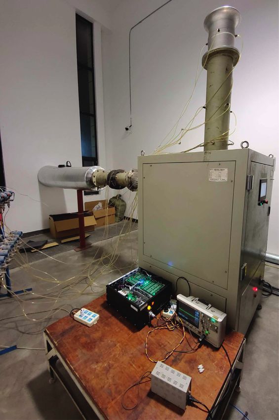
Shock and Vibration 5

 2 88

 1.9 86

 84
 1.8

 Polytropic efficiency (%)
 82
 Pressure Ratio

 1.7
 80
 1.6
 78
 1.5
 76

 1.4 74

 1.3 72
 0.4 0.6 0.8 1 1.2 1.4 0.4 0.6 0.8 1 1.2 1.4
 Dimensionless mass flow rate Dimensionless mass flow rate

 CR=2.61% CR=2.61%
 CR=4.35% CR=4.35%
 CR=6.09% CR=6.09%
 (a) (b)
 1.95 86
 1.9 85.5
 1.85 85
 1.8
 84.5
 Polytropic efficiency (%)

 1.75
 84
 Pressure Ratio

 1.7
 83.5
 1.65
 83
 1.6
 82.5
 1.55
 1.5 82

 1.45 81.5

 1.4 81
 0.02 0.03 0.04 0.05 0.06 0.07 0.08 0.09 0.02 0.03 0.04 0.05 0.06 0.07 0.08 0.09
 CR CR

 32000 r/min 32000 r/min
 28800 r/min 28800 r/min
 25600 r/min 25600 r/min
 (c) (d)

Figure 3: Overall performance maps of pressure ratio and efficiency over CR. (a) Pressure ratio over mass flow rate. (b) Polytropic efficiency
versus mass flow rate. (c) Pressure ratio over clearance ratio. (d) Polytropic efficiency over clearance ratio.

position of the impeller. Thus, the impeller could always and pressure probes were fixed on the inlet and outlet pipes
achieve the optimal efficiency without surging. to record the operating status of the machine under different
 tip clearances. The axial magnetic bearing control was ex-
5. Experimental Verification ecuted by connecting the power amplifier board and the
 digital-to-analogy converter to the computer. The impeller
5.1. The Performance Map Experiment. As shown in Fig- static clearance was 0.5 mm when installed. The magnetic
ure 10, the experimental device composed a commercial levitation controller was used to adjust the rotor position so
CIGU magnetic levitation centrifugal blower, installed a that the clearance varied from 0.3 mm to 0.7 mm during the
collector in front of the impeller inlet. Besides, temperature operation.
6 Shock and Vibration

 85
 80
 75
 70
 65

 Surge margin (%)
 60
 55
 50
 45
 40
 35
 30
 25
 20
 0.02 0.03 0.04 0.05 0.06 0.07 0.08 0.09
 CR

 32000 r/min
 28800 r/min
 25600 r/min
 Figure 4: Surge margin over CR.

 Cm
 130
 120 CR=2.61% CR=4.35%
 110
 100
 90
 80
 70
 60
 50
 40 CR=6.09% CR=7.83%
 30
 20
 10
 0
 ms-1
 Figure 5: Meridional velocity contour at different CRs.

 Table 2: The flow rate and pressure rise of surge point under different clearances.
 3
Volume flow rate (m /min) Pressure rise (kPa) Clearance value (mm)
45.00 94.7 0.3
42.00 94.9 0.4
40.00 94.5 0.5
36.00 90.3 0.7
34.50 89.5 0.8
33.00 88 0.9

 The experiment obtained the efficiency of the whole gauge. When the outlet pressure had obvious periodic os-
machine by measuring the temperature and pressure of the cillations, it was recorded as the surge point at the current
inlet and outlet. The flow rate was obtained from the static speed.
pressure in the inlet venturi. For the determination of surge, It can be seen from Figure 11 that the CFD results are
the outlet pipeline was equipped with a precision pressure more consistent with the experimental results in terms of
Shock and Vibration 7

 100

 95 clearance adjust
 region
 90

 85 constant clearance

 Pressure rise (kPa)
 region
 80

 75

 70

 65

 60

 55

 50
 20 25 30 35 40 45 50 55 60 65 70
 Volume flow rate (m3/min)
 Figure 6: 32000 r/min constant and variable clearance region.

 Table 3: Errors of the equation.
No. Prediction C (mm) Residual Standard residual
1 0.289341 0.010659 0.5783769
2 0.407452 −0.00745 −0.404370
3 0.495326 0.004674 0.2536037
4 0.729300 −0.02930 −1.589896
5 0.803768 −0.00377 −0.204487
6 0.874812 0.025188 1.3667722

 Axial magnetic bearing Radial magnetic bearing Axial magnetic bearing

 Rotor
 Φ 65

 Displacement sensor

 469

 Figure 7: The sketch of the rotor.

 Table 4: Parameters of the AMB.
Item Symbol Radial AMB Axial AMB Unit
Vacuum permeability μ0 4π × 10− 7 4π × 10− 7 N/A2
Pole area A 375 768.8 mm2
Coil turns N 148 240
Bias current I0 2.5 2.5 A
8 Shock and Vibration

 control
 I+i
 signal power
 amplifier

 magnetic bearing
 reference
 signal + f
 controller -
 - rotor
 -
 mg +

 I-i
 power
 amplifier

 displacement
 sensor

 Figure 8: Magnetic bearing system.

 Reference
 Pressure signal
 clearance
 Optimal model of
 Flow signal + controller
 fitting efficiency –
 Magnetic
 suspension
 blower Axial displacement signal of impeller
 system
 Generate electromagnetic force power
 AMB
 amplifier

 Figure 9: Impeller suspension position control flowchart.

overall performance indicators. In the calculation of the position of the impeller can be found and real-time control
pressure ratio, the maximum deviation between CFD and can be carried out according to this law.
the experiment is 1.8%; as for the polytropic efficiency, CFD According to the optimal impeller suspension position
is overestimated by about 1%. This is mainly due to the control method in Figure 9, by varying the valve opening, the
deviation of the adiabatic wall assumed in the calculation experiment shows that the impeller suspension position
and the fact that friction loss, leakage loss, and some changes with the altering of the flow rate and pressure rise. It
transient losses could not be captured through steady-state can be seen from Figure 13 that, as the axial suspension
calculations. The specific trend is very similar between the position of the impeller varies, the outlet pressure and flow
CFD and experimental data. In addition, the relatively large rate of the blower also changes. When the impeller levitation
difference between CFD and experimental data at high speed gap decreases, the voltage at the axial levitation position
is mainly due to the failure of the CFD model to consider the sensor of the rotor gradually decreases, the blower pressure
deformation of the impeller at high speed. rise declines, and the blower inlet flow rate increases.
 Conversely, as the impeller suspension gap increases, the
 pressure rise increases and the flow rate decreases. The above
5.2. Experimental Research on Variable Impeller Axial experimental results show that the use of the control method
 Suspension Clearance Control proposed in this paper makes the working position of the
 magnetic levitation blower gradually move from the point
5.2.1. Test of the Clearance Control Law. In order to reflect close to the surge condition to the stable working region on
the relationship between the axial suspension position of the the characteristic curve.
impeller and the efficiency of the blower, according to The trajectories of both ends of the rotor during the axial
formula (3), as shown in Figure 12, the optimal efficiency change of the rotor are shown in Figure 14. Cmax in Figure 14
curve and the change of the reference suspension position of reflects the radial AMB clearance. It can be seen that the
the impeller are fitted with the variation of pressure rise and trajectory of the rotor displacement is below 0.3Cmax.
flow rate. It can be seen from Figure 12 that, as the flow rate Therefore, the compressor could work stably for a long time
increases, the impeller gap gradually decreases, and as the according to the ISO14839-2 standard [21]. Besides, it shows
pressure increases, the impeller gap decreases. Therefore, that the PID method can effectively control the rotor during
under different conditions, a suitable axial adjustment operation.
Shock and Vibration 9

 ①

 ②

 ③

 ⑤ ④

 ⑥

 ⑦

 ⑧

 ①.Bell ring ②&④. Pressure gauge
 ③&⑤. Temperature sensor ⑥.AMB power
 amplifier ⑦. Oscilloscope ⑧.DAC
 (a)
 Figure 10: Continued.
10 Shock and Vibration

 Φ200

 600
 Temperature sensor x4

 300
 Pressure gauge x4

 600
 Flow direction

 600 200
 Φ200

 Compressor
 gauge x4

 Temperature
 Pressure

 sensor x4

 (b)

 Figure 10: Test configuration. (a) Test equipment. (b) Test rig dimensions.

5.2.2. Results on Control Performance Under Surge. The CFD optimal efficiency curve and the experimental test
control law was programmed into the magnetic bearing efficiency. The test efficiency in the fixed gap area is in good
controller. During the test, the speed rose to the rated speed of agreement with CFD while the test efficiency in the surge
32000 r/min, and the throttle valve gradually closed from the control region is 0.5% lower than the CFD value. The reason
maximum opening to the surge flow rate. The flow rate, is that the steady-state CFD failed to capture the complex
pressure rise, and efficiency of the compressor were recorded. flow phenomenon at low flow rate which leads to an
 Limited by the magnetic bearing structure, the adjust- overestimate of polytropic efficiency. Besides, to avoid a
ment range of the axial gap in the experiment was only surge shutdown during the test, the actual gap value was
0.3 mm–0.7 mm. It can be seen from Figure 15(a) that, in the slightly larger than the theoretical optimal value, but the
fixed gap range, the test pressure ratio is in good agreement general trend is very consistent. In general, under the test
with the CFD results. When the throttle valve is gradually clearance control range of 0.3 mm–0.7 mm, the surge margin
close to the surge flow rate, the controller starts following the of the impeller has increased from 28% to 55% and the
control law to enlarge the axial clearance so that the blower minimum flow rate at which the impeller can work under the
can work normally in the surge area of the original fixed rated speed has dropped from 44 m3/min to 36 m3/min while
clearance. Figure 15(b) shows the comparison between the the polytropic efficiency remains the same.
Shock and Vibration 11

 2 88

 86
 1.9

 Polytropic compression efficiency (%)
 84
 1.8
 82
 Pressure ratio

 1.7 80

 1.6 78

 76
 1.5
 74
 1.4
 72

 1.3 70
 0.4 0.6 0.8 1 1.2 1.4 0.4 0.6 0.8 1 1.2 1.4
 Dimensionless mass flow rate Corrected mass flow rate

 CFD CR=2.61% Exp CR=2.61% CFD CR=2.61% Exp CR=2.61%
 CFD CR=4.35% Exp CR=4.35% CFD CR=4.35% Exp CR=4.35%
 CFD CR=6.09% Exp CR=6.09% CFD CR=6.09% Exp CR=6.09%
 (a) (b)

Figure 11: Comparison of CFD and experimental data. (a) Comparison of pressure ratio over mass flow between CFD and experimental
results. (b) Comparison of polytropic efficiency over mass flow between CFD and experimental results.

 1
 Tip clearance (mm)

 0.8
 96
 0.6 94
 a)

 0.4 92
 P (kP

 90
 0.2
 46 44 88
 42 40 38 36 34 32
 Q (m3/min)
 Figure 12: The axial clearance variation with flow rate and pressure rise.

 0.9 105 45
 Tip clearance (mm)

 Pressure Rise (kPa)

 Volume flow rate

 0.7 99 43
 (m3/min)

 B 93 41
 0.5
 A C 87 39
 0.3 81 37
 0.1 75 35
 0 50 100 150 200 0 50 100 150 200
 Time (s) Time (s)

 Pressure Rise
 Volume flow rate
 (a) (b)

Figure 13: Test results of axial suspension control. (a) Axial displacement signal of impeller. (b) Pressure rise and volume flow rate.
12 Shock and Vibration

 75 75 75 75
 0.3 Cmax 0.3 Cmax 0.3 Cmax 0.3 Cmax

 Displacement (μm)

 Displacement (μm)
 Displacement (μm)

 Displacement (μm)
 25 25 25 25

 -25 -25 -25 -25

 -75 -75 -75 -75
 -75 -25 25 75 -75 -25 25 75 -75 -25 25 75 -75 -25 25 75
 Displacement (μm) Displacement (μm) Displacement (μm) Displacement (μm)
 (a) (b)
 75 75
 Displacement (μm) 0.3 Cmax 0.3 Cmax

 Displacement (μm)
 25 25

 -25 -25

 -75 -75
 -75 -25 25 75 -75 -25 25 75
 Displacement (μm) Displacement (μm)
 (c)

 Figure 14: Test results of rotor axis trajectory. (a) Axis trajectory at A. (b) Axis trajectory at B. (c) Axis trajectory at C.

 100 0.9

 95 0.88
 Polytropic Compression Efficiency (%)

 90 0.86

 85 0.84
 Pressure rise (kPa)

 80 0.82

 75 0.8

 70 0.78

 65 0.76

 60 0.74

 55 0.72

 0.7
 50 30 35 40 45 50 55 60 65 70
 30 35 40 45 50 55 60 65 70
 Volume flow rate (m3/min)
 Volume flow rate (m3/min)
 Experimental data
 Adjust CR by CFD
 CFD-results
 Constant CR by CFD
 Experimental data with CR control
 (a) (b)

Figure 15: Test results of flow, pressure, and efficiency under the clearance control law. (a) Pressure ratio over volume flow rate.
(b) Polytropic compression efficiency over flow rate.

6. Conclusions tip clearances at different speeds. After that, an axial
 clearance control law based on the blower flow rate and
The magnetic levitation blower can adjust the tip clearance pressure was proposed. Then, the control law was tested by
value during operation to optimize the efficiency of the experiments. The conclusions of this paper are as follows:
impeller and significantly widen the surge margin when it
deviates from the design point. This paper adopted CFD (1) The efficiency and pressure ratio of the impeller
analysis and experimental verification to study the perfor- decreases linearly with the increase of the tip
mance and fluid flow state of the impeller under six different clearance. Within CR 2.61% to 7.83%, the pressure
Shock and Vibration 13

 ratio drops by 0.02 for every 1% increase in CR and [7] B.-J. Cha, B.-J. Im, and S.-S. Yang, “A study on the instabilities
 the polytropic compression efficiency decreases by of the centrifugal compressor with variable diffuser,” Trans-
 0.5%. actions of the Korean Society of Mechanical Engineers B,
 vol. 26, no. 8, pp. 1123–1131, 2002.
 (2) The surge margin of the impeller enlarges with the [8] K. M. Arthur, H. Basu, and S. Y. Yoon, “Stabilization of
 augment of the tip clearance mainly because the compressor surge in systems with uncertain equilibrium
 clearance flow relieves the leading-edge separation flow,” ISA Transactions, vol. 93, pp. 115–124, 2019.
 under the low flow rate. The simulation results show [9] D. Sanadgol and E. Maslen, “Effects of actuator dynamics in
 that, within the scope of the study, for every 1% active control of surge with magnetic thrust bearing actua-
 increase in CR, the surge margin would increase by tion,” in Proceedings of the IEEE/ASME International Con-
 7.8%. ference on Advanced Intelligent Mechatronics, pp. 1091–1096,
 Monterey, California, July 2005.
 (3) Through active control, under the test clearance [10] S. Y. Yoon, Z. Lin, and P. Allaire, Control of Surge in Cen-
 control range of 0.3 mm–0.7 mm, the surge margin trifugal Compressors by Active Magnetic Bearings, Springer,
 of the blower increases from 26% to 59%, the surge Berlin, Germany, 2012.
 flow rate at the rated speed reduces from 44 m3/min [11] S. Y. Se Young Yoon, Z. Zongli Lin, and P. E. Allaire, “Ex-
 to 36 m3/min while the polytropic efficiency remains perimental evaluation of a surge controller for an AMB
 unchanged. supported compressor in the presence of piping acoustics,”
 IEEE Transactions on Control Systems Technology, vol. 22,
 (4) Bearings with active control can ensure that the
 no. 3, pp. 1215–1223, 2014.
 impeller obtains the corresponding performance at [12] S. Y. Yoon, Z. Lin, W. Jiang, and P. E. Allaire, “Flow-rate
 the design point. When it deviates from the design observers in the suppression of compressor surge using active
 point, the working range is expanded by adding the magnetic bearings,” Journal of Turbomachinery, vol. 135,
 tip clearance so that the same impeller can be used in no. 4, pp. 2775–2784, 2013.
 more scenarios which significantly reduce the period [13] M. Tang, J. Zhou, and H. Cui, “Surge control of the centrifugal
 of development of the impeller. compressor with magnetic thrust bearing,” Process Automa-
 tion Instrumentation, vol. 38, no. 5, pp. 15–19, 2017.
 [14] X. Guan, J. Zhou, and C. Jin, “Influence of different operating
Data Availability conditions on centrifugal compressor surge control with
 active magnetic bearings,” Engineering Applications of Com-
The data used to support the findings of this study are
 putational Fluid Mechanics, vol. 13, no. 1, pp. 824–832, 2019.
available from the corresponding author upon request. [15] J. Sun, J. Zhao, and K. Wang, “Online surge detection method
 based on axial displacement sensor of MSCC,” IEEE Sensors
Conflicts of Interest Journal, vol. 19, no. 15, pp. 6029–6036, 2019.
 [16] X. Ma, S. Zheng, and K. Wang, “Active surge control for
The authors declare that they have no conflicts of interest magnetically suspended centrifugal compressors using a
regarding the publication of this paper. variable equilibrium point approach,” IEEE Transactions on
 Industrial Electronics, vol. 66, no. 12, pp. 9383–9393, 2019.
 [17] X. Han, G. Liu, B. Chen, and S. Zheng, “Surge disturbance
References suppression of AMB-rotor systems in magnetically suspen-
 sion centrifugal compressors,” IEEE Transactions on Control
 [1] Y. Senoo, “Pressure loss due to the tip-clearance of impeller Systems Technology, 2021.
 blades in centrifugal and axial blowers,” Transactions of the [18] A. Bonfitto, L. M. Castellanos, A. Tonoli, and N. Amati,
 Japan Society of Mechanical Engineers, vol. 108, 1984 Lecture “Offset-free model predictive control for active magnetic
 Ser. 1984-07). bearing systems,” Actuators, vol. 7, no. 3, 2018.
 [2] Y. Senoo and M. Ishida, “Deterioration of compressor per- [19] L. M. Castellanos Molina, A. Bonfitto, and R. Galluzzi,
 formance due to tip clearance of centrifugal impellers,” “Offset-Free Model Predictive Control for a cone-shaped
 Journal of Turbomachinery, vol. 109, no. 1, pp. 55–61, 1987. active magnetic bearing system,” Mechatronics, vol. 78, Article
 [3] Z. Liu, Y. Ping, and M. Zangeneh, “On the nature of tip ID 102612, 2021.
 clearance flow in subsonic centrifugal impellers,” Science [20] X. Liu and L. Zhao, “Approximate nonlinear modeling of
 China Technological Sciences, vol. 56, no. 9, pp. 2170–2177, aircraft engine surge margin based on equilibrium manifold
 2013. expansion,” Chinese Journal of Aeronautics, vol. 25, no. 5,
 [4] J. Galindo, A. Tiseira, R. Navarro, and M. A. López, “Influence pp. 663–674, 2012.
 of tip clearance on flow behavior and noise generation of [21] ISO 14839-2, Mechanical Vibration—Vibration of Rotating
 centrifugal compressors in near-surge conditions,” Interna- Machinery Equipped with Active Magnetic Bearings—Part 2:
 tional Journal of Heat and Fluid Flow, vol. 52, pp. 129–139, Evaluation of Vibration, ISO 14839-2, 2004.
 2015.
 [5] M. Hewkin-Smith, G. Pullan, S. D. Grimshaw, E. M. Greitzer,
 and Z. S. Spakovszky, “The role of tip leakage flow in spike-
 type rotating stall inception,” Journal of Turbomachinery,
 vol. 141, no. 6, 2019.
 [6] L. M. Du and Y. Z. Gong, “Prediction and analysis of per-
 formance of a centrifugal compressor with casing treatment
 under multiple working conditions,” Applied Mechanics and
 Materials, vol. 448-453, pp. 3434–3439, 2013.
You can also read