Micro mechanical insights into the dynamics of crack propagation in snow fracture experiments
←
→
Page content transcription
If your browser does not render page correctly, please read the page content below
www.nature.com/scientificreports
OPEN Micro‑mechanical insights
into the dynamics of crack
propagation in snow fracture
experiments
Grégoire Bobillier1*, Bastian Bergfeld1, Jürg Dual2, Johan Gaume1,3, Alec van Herwijnen1 &
Jürg Schweizer1
Dry-snow slab avalanches result from crack propagation in a highly porous weak layer buried within a
stratified and metastable snowpack. While our understanding of slab avalanche mechanisms improved
with recent experimental and numerical advances, fundamental micro-mechanical processes remain
poorly understood due to a lack of non-invasive monitoring techniques. Using a novel discrete
micro-mechanical model, we reproduced crack propagation dynamics observed in field experiments,
which employ the propagation saw test. The detailed microscopic analysis of weak layer stresses and
bond breaking allowed us to define the crack tip location of closing crack faces, analyze its spatio-
temporal characteristics and monitor the evolution of stress concentrations and the fracture process
zone both in transient and steady-state regimes. Results highlight the occurrence of a steady state
in crack speed and stress conditions for sufficiently long crack propagation distances (> 4 m). Crack
propagation without external driving force except gravity is possible due to the local mixed-mode
shear-compression stress nature at the crack tip induced by slab bending and weak layer volumetric
collapse. Our result shed light into the microscopic origin of dynamic crack propagation in snow slab
avalanche release that eventually will improve the evaluation of avalanche release sizes and thus
hazard management and forecasting in mountainous regions.
Highly porous brittle materials subject to mixed mode (compressive-shear) loading exhibit localized progressive
failure resulting in the nucleation of a closing crack that may propagate dynamically1–3. In snow, this process—
also known as anticrack—is known to occur in weak snowpack layers, which have a peculiar and highly aniso-
tropic structure related to their formation mechanism through temperature m etamorphism4. When buried below
a cohesive snow slab, the snowpack becomes metastable and a small perturbation may lead to crack propagation
in the weak layer across the slope and subsequent snow slab avalanche release5,6. During the past decade, our
understanding of fracture processes in snow has greatly improved by the development of a fracture mechanical
field test known as the propagation saw test (PST)7–9. The PST involves isolating a snow column, initiating a
crack by a sawing in a pre-identified weak layer until a critical crack length is reached, and crack propagation
occurs without additional loading. The PST allows analyzing the onset and dynamics of crack propagation and
deriving mechanical properties using displacement-tracking t echniques10,11. In addition, analytical and numeri-
cal models based on fracture and/or continuum mechanics were developed to investigate crack propagation and
avalanche release3,12–17.
These models provided new insight into key parameters and driving forces, however, the micro-mechanical
processes involved during dynamical crack propagation are still essentially unknown. While their direct obser-
vation is so far not feasible, the discrete element method (DEM) has previously been successfully used to study
the influence of snow microstructure on the mechanical behavior of snow18–21 and crack propagation in weak
layers15,22. Therefore, DEM is an appealing method to study the effect of the complex and highly porous snow
microstructure on the dynamics of crack propagation, which does not require the assumption of a complex mac-
roscopic constitutive model. DEM allows the generation of highly porous samples crucial to model snow failure
and was, for instance, used to perform 2-D simulations of a PST yielding good agreement with field experiments.
1
WSL Institute for Snow and Avalanche Research SLF, Davos, Switzerland. 2Institute for Mechanical Systems, ETH
Zurich, Zurich, Switzerland. 3SLAB Snow and Avalanche Simulation Laboratory, EPFL Swiss Federal Institute of
Technology, Lausanne, Switzerland. *email: gregoire.bobillier@slf.ch
Scientific Reports | (2021) 11:11711 | https://doi.org/10.1038/s41598-021-90910-3 1
Vol.:(0123456789)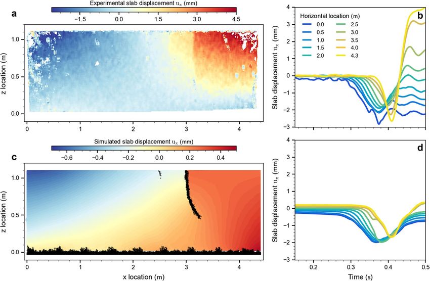
www.nature.com/scientificreports/
Mechanical property Macroscopic
Slope angle (degree) 0
Mean weak layer density (kg m−3) 138
Mean slab layer density (kg m−3) 154
Weak layer thickness (m) 0.02
Slab layer thickness (m) 1.1
PST fracture type SF + END
Critical crack length ac (m) 0.32
Table 1. Properties of PST experiment.
However, the oversimplified shape (triangular structure) and the 2-D character of the weak layer employed by
Gaume et al.15 prevented a detailed analysis of the internal stresses during crack propagation.
Our aim is therefore to numerically simulate an exemplary experimental PST with a 3-D DEM model to
better understand the micromechanics involved during dynamical snow fracture. We first present a method to
evaluate the location of the crack tip, which is particularly challenging due to the closure of crack faces during
propagation. Our model reproduced the experimentally observed displacement field, accelerations and crack
propagation speed well. Furthermore, the model provides detailed insight into the micro-mechanical processes
and stresses within the weak layer and allows us to identify the main drivers of crack propagation.
Methods
Experimental data. The experimental data we use for model development were obtained with a field
experiment, a propagation saw test (PST), on a flat and uniform site close to Davos, Switzerland; the experi-
mental procedures are described in detail by Bergfeld et al.11. The PST is a fracture mechanical test for s now7,23,
consisting of isolating a 30 cm wide snow column of variable length over the entire snowpack height containing
a buried weak layer. While the standard guideline24 recommend a column length of 1.20 m, in our experiment
the PST was 4.35 m long. The snowpack was characterized with a traditional manual snow profile, providing
information on density, layer thickness and snow grain type.
The side wall of the PST was speckled with black ink to increase the contrast and perform digital image cor-
relation (DIC) analysis. The experiment was filmed using a high-speed camera (Phantom, VEO710) at 14,000
frames per second and a full width resolution of 1280 pixels. The DIC analysis provided high-resolution slab,
weak layer and substratum displacements11. Table 1 summarizes some key properties of the PST experiment.
The critical crack length (ac ) is the length of the artificial crack created by sawing through the weak layer when
self-propagation starts. Mean slab density was obtained from the thickness weighted layer densities (measured
manually). Snow samples including the weak layer (0.30 m × 0.30 m × 0.30 m) were transported in an insulated
foam box from the test site to the cold laboratory where weak layer density was derived from micro-computed
tomography25. The crack propagated to the very end of the column (PST fracture type: END), although a slab
fracture (SF) occurring towards the end of the column was revealed by the DIC analysis.
Discrete element method and contact model. To generate a model of the propagation saw test, we
used the three-dimensional discrete element method (DEM). DEM, first introduced by Cundall and Strack26,
is a numerical tool, consisting of a large number of discrete interacting particles, commonly employed to study
large deformations in granular-like assemblies. We used the PFC3D (v5) software (http://www.itascacg.com).
The particle contact law we used is called a parallel-bond contact model (PBM) introduced by Potyondy and
Cundall27. The PBM provides the mechanical behavior of a finite-sized piece of cement-like material connect-
ing two particles. The PBM component acts in parallel with a classical linear contact model and establishes an
elastic interaction between the particles. The PBM mechanical parameters include the contact elastic modulus,
Poisson’s ratio, restitution coefficient, and the friction coefficient . If particles are bonded, the bond part will act
in parallel to the contact part. The bonded part is described by the bond elastic modulus, the bond Poisson’s
ratio and the bond strength; shear and tensile strength (“Appendix 3” illustrates the PFC parallel bond model
(PBM) with the mechanical parameters for the bonded and unbonded state and the different bond behaviors
e.g.; tension–compression, shear, bending and torsion). Bobillier et al.18 related PBM contact model parameters
to macroscopic snow parameters. The PST model include macroscopic mechanical and particle parameters. The
macroscopic mechanical response was obtained with numerical load-controlled shear and compression tests as
presented by Bobillier et al.18 and summarized in Table 2.
System generation. The simulated three-dimensional PST consisted of three layers: a rigid basal layer, a
weak layer (porous and anisotropic structure) and a slab layer (dense and uniform structure). The basal layer was
composed of a single square matrix layer of particles with a radius of r = 2.5 mm. The weak layer was created by
cohesive ballistic deposition18,28 resulting in a porosity of 80% for a particle radius r = 2.5 mm with a layer thick-
ness of h = 20 mm. The slab layer was generated by cohesionless ballistic deposition18,29. The porosity of the slab
layer was 45% for a particle radius of r = (10.5 ± 0.5) mm (uniform distribution) and slab thickness was H = 1.1 m,
as in the experiment. The variation in radius was introduced to prevent close packing. The generated weak layer
microstructure is unique but applying homothetic transformation would change its thickness while keeping
Scientific Reports | (2021) 11:11711 | https://doi.org/10.1038/s41598-021-90910-3 2
Vol:.(1234567890)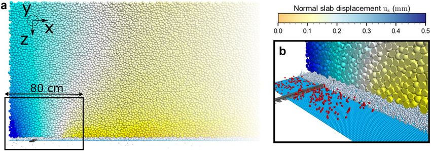
www.nature.com/scientificreports/
Mechanical property Macroscopic Particles
Poisson’s ratio υu − 0.3
Restitution coefficient eu − 0.1
Friction coefficient µu − 0.5
Mean weak layer density (kg m−3) 130 650
Mean slab layer density (kg m−3) 154 280
Slab porosity 45% −
Weak layer porosity 80% −
*Slab elastic modulus (MPa) 5.2 7
*Weak layer elastic modulus (MPa) 1 47.5
*Slab tensile strength (kPa) Infinite Infinite
*Weak layer tensile strength (kPa) 2 144
*Weak layer shear strength (kPa) 1.2 144
*Weak layer compressive strength (kPa) 4.3 −
Table 2. Mechanical properties of DEM model. An asterisk (*) indicates those properties that were selected by
optimizing the agreement between experiment and simulation.
Figure 1. (a) Simulation of PST at the beginning of self-sustained crack propagation. The basal layer is
represented in light blue (r = 2.5 mm), the weak layer (WL) in white (r = 2.5 mm), and the slab layer is colored
by its normal displacement [colored from no displacements in yellow to 0.5 mm displacement in blue,
r = (10.5 ± 0.5) mm]. The snow saw is represented in dark grey. (b) Internal WL fracture process around the
fracture process zone (WL and slab were removed from the visualization). Red necks represent broken bonds in
the weak layer. At the beginning of self-sustained crack propagation, many bonds are breaking ahead of the saw
tip.
its mechanical behavior18 (Figure supplement). Slab and weak layer fabric tensors were computed and there
eigenvalues used to evaluate the degree of anisotropy (spheres: 1 ≈ 2 ≈ 3, discs: 1 ≈ 2 ≫ 3, and rods:
1 ≫ 2 ≈ 3). Benn30 defined an isotropy index (I) and an elongation index (EI) to describe the fabric shape as:
3 2
I = ; EI = 1 − .
1 1
Slab isotropy index and elongation were similar to values reported for layers of rounded grains
(I = 0.94; EI = 0.08); the weak layer shows transverse isotropic symmetry similar to layers of depth hoar, surface
hoar or facets ( I = 0.75; EI = 0.25)31. Particle densities were adjusted to fit the observed macroscopic densities
in accordance with the macroscopic sample porosities (Table 2).
To generate the large DEM simulation domain needed to reproduce the experimental PST, we generated a cell
under spatial periodic boundary conditions (base, weak layer and slab) large enough to avoid sample size effects
(0.50 m × 0.50 m × 1.12 m)18. We then replicated and joined multiple cells (9 in total) to obtain the complete
PST system (≈ 311,000 particles, ≈ 730,000 contacts). Finally, the spatial boundary conditions were defined as
non-periodic and the system geometry was cut to fit the experimental set up (4.35 m × 0.30 m × 1.12 m). This
generation technique allowed to rapidly generate a large system (~ 1 m3 per min; Intel Xeon CPU 2.60 GHz,
14 Cores, RAM 256 Gb). The snow saw was modeled with a PFC3D rigid wall with dimensions similar to the saw
used in the field experiment (400 mm × 35 mm × 3 mm, Fig. 1; Figure supplement). Following the standard PST
guideline, the saw opened a crack while cutting the weak layer at a constant speed of (1 m s−1). The saw speed
selected was twice as high as the experimental speed to reduce the simulation time, but was still small compared
to the crack propagation speed. The saw cut causes local forces in the weak layer that break bonds at the saw tip.
Scientific Reports | (2021) 11:11711 | https://doi.org/10.1038/s41598-021-90910-3 3
Vol.:(0123456789)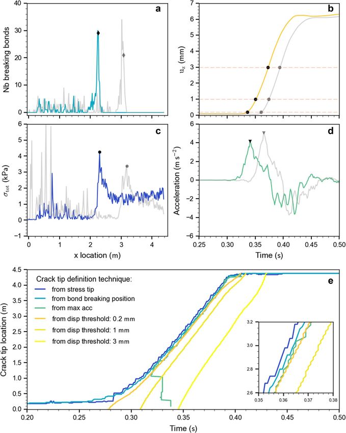
www.nature.com/scientificreports/
Simulated PST data acquisition. From the DEM simulations, we retrieved particle displacements, forces
acting on particles and the positions of broken bonds. The displacement of the slab was obtained from particle
displacements and averaged over cells of 20 mm × 300 mm × 20 mm. The stresses (σzz , τzx ) were calculated from
the measured forces at the interface between the basal layer and the weak layer as:
n
x
1
σzz (x) = F (n) (x)
ly �x n=1 z
nx
1
τzx (x) = F (n) (x)
ly �x n=1 x
nx : number of contacts[x; x + x ]
The basal layer was discretized over the column length in order to determine the stresses (Δx = 20 mm, 8 parti-
cles). Fz and
Fx are the contact forces acting on the basal layer in the normal and tangential direction, respectively,
and ly x is the area of the basal layer where the forces are measured (ly correspond to the PST width: 0.30 m).
The positions of broken bonds were recorded from the difference in the number of bonded contacts between
two time steps, the missing bonded contacts are defined as broken bonds and their corresponding positions are
recorded.
Crack speed was defined using c = �d/�t where d is the difference in crack tip position (for definition
see below) between two time steps and t the time step. To increase the precision of the data without distorting
the signal tendency the finite difference method was used to approximate the derivative of the crack tip position
as function of time employing Savitzky–Golay filtering. Crack speed was computed and filtered with a 9-point
linear Savitzky–Golay fi lter32.
Selection of material properties. While the slab and weak layer density were obtained during the field
experiment, we needed to assume the elastic modulus and shear strength for both layers based on literature
values10,31,33. To match the dynamics of slab displacement during crack propagation (collapse height, slab dis-
placement speed), we simulated PSTs with different pairs of elastic moduli ( Eslab, Ewl ) selected within the range
of the typical literature values corresponding to the layer densities we measured in the experiment ( Eslab range
4–6 MPa; Ewl range 0.5–1 MPa). We also tuned the weak layer shear strength (τwl th) to match the experimental
critical crack length (ac) and the collapse height with respect to the admissible range given by the measured
mean density of the weak layer (τwl th range 1–2 kPa).
Onset of crack propagation. The critical length of the saw cut, i.e. the onset of self-sustained crack propa-
gation, was measured as the length of the open crack induced by sawing. The critical length measured in a
field experiment is subject to inherent uncertainties induced by the manual sawing (on the order of ± 5 cm).
In the simulation, we arbitrarily defined the critical cut length as the saw position when at least one bond was
broken 0.20 m in front of the saw tip. Using a realistic value for the weak layer shear strength of 1.2 kPa34 we
obtained a critical cut length in the numerical simulation of ac = 0.28 m, which is shorter than in the experiment
(ac = 0.32 m).
Crack tip definition. To accurately determine crack speed, it is crucial to define the position of the crack tip.
This is not straightforward since we do not have an opening crack, but a closing (anti-)crack. Hence, we suggest
four metrics for determining the position of the crack tip: (a) bond-breaking position, (b) normal displacement
thresholds, (c) maximum stress, and (d) maximum normal slab acceleration (Fig. 2). Definition (a) is based on
the number of broken bonds at a given time step. Starting from the end of the column, at each time step the crack
tip is defined as the position where the number of broken bonds corresponds to 70% of the maximum number
of broken bonds (Fig. 2a: diamond dots). Definition (b) is based on a normal displacement threshold as sug-
gested by van Herwijnen and J amieson9. For every subset, the time is recorded when the displacement exceeds
the threshold value; to compute the speed, d is equal to the discretization length ( x = 20mm) and t is the
recorded time difference (Fig. 2b). Figure 2e shows the temporal evolution of the crack tip position defined
with three different threshold values of normal displacement (three shades of yellow). Increasing the threshold
value shifts
the crack tip position in time. In definition (c), the crack tip is the position of maximum total stress
(σtot = σzz 2 + τ 2 ; Fig. 2c). Finally, in definition (d), the crack tip is the position of maximum normal accel-
xz
eration as a function of time (Fig. 2d). Figure 2e, f shows good agreement between the four methods of crack
tip definition; the crack speed between 1 m and the end of the column shows the same behavior regardless of
the type of metric used. The crack tip location based on the maximum stress definition is ahead of the locations
obtained with the other methods (Fig. 2e, f) in line with the assumption that stresses induce fracture. The crack
tip definition based on the bond breaking position provides the maximum of information during the cutting
phase. While the metric based on acceleration (d) was used to define the crack tip position, due to noise in parti-
cle acceleration shortly after the onset of crack propagation, it could not be used to reliably compute crack speed.
Scientific Reports | (2021) 11:11711 | https://doi.org/10.1038/s41598-021-90910-3 4
Vol:.(1234567890)
www.nature.com/scientificreports/

                                  Figure 2.  (a) Number of bonds breaking at a given time step along the length of the column; distributions
                                  for two different time steps shown (0.28 s and 0.3 s). (b) Temporal evolution of the normal slab displacement
                                  for two locations (x = 2 m and 3 m). The orange dashed horizontal lines correspond to three displacement
                                  thresholds (0.2, 1 and 3 mm). (c) Total stress along the length of the column at two different time steps (0.34 s
                                  and 0.36 s). (d) Temporal evolution of the slab normal acceleration for two x locations (at 2 m and 3 m).
                                  Markers show the position or time obtained to define the crack tip (in a, b, c, d). (e) Temporal evolution of the
                                  crack tip position for different metrics of crack tip definition. (f) Inset shows zoom into the temporal evolution
                                  of the crack tip position.

Scientific Reports |   (2021) 11:11711 |               https://doi.org/10.1038/s41598-021-90910-3                                                      5

                                                                                                                                               Vol.:(0123456789)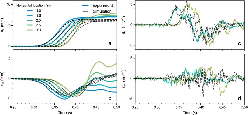
www.nature.com/scientificreports/
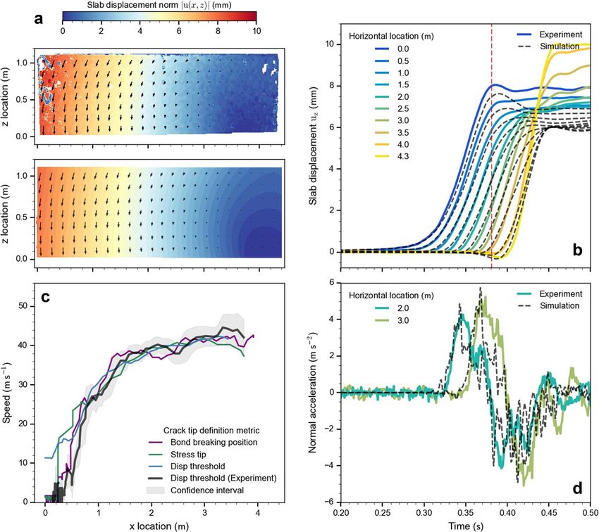
Figure 3. Comparison of experimental and simulated PST results. (a) Experimental (top) and simulated
(bottom) displacement field norm (magnitude) when the crack tip reached 3.7 m (|u(x, z)| = ux 2 + uz 2 ).
The displacement field is colored from no-displacement in blue to 10 mm displacement in red. (b) Temporal
evolution of the normal displacement averaged over the height. The colors represent the horizontal location and
the black dashed line the corresponding location for the simulated PST. The red dashed line corresponds to the
time when the crack tip reached 3.7 m, i.e. corresponds to the displacement field shown in (a). (c) Crack speed
evolution along the PST beam. The grey line shows the experimental crack speed with its confidence interval
(grey envelope) and the blue, violet and green lines the simulated crack speed. Crack speeds are computed from
different crack tip definitions: grey and blue line based on displacement threshold of 0.2 mm, green line based
on maximum stress and violet line based on the position of breaking bonds. (d) Temporal evolution of the
normal slab acceleration for two locations [at 2 m and 3 m; line colors as in (b)].
Time step. The length of the time step was determined as function of the particle properties according to
ρ
�t ≈ f r
E
where ρ and r are the smallest particle density and radius, respectively, E is the largest bond or particle elastic
modulus, and f is a safety factor (0.8). PFC3D software dynamically calculated the time step in this manner to
ensure the stability of the DEM.
Results
Dynamics of crack propagation and crack propagation speed. The dynamics of key measures
observed in the PST field experiment were very well reproduced by the DEM simulation. The displacement field
exhibited the same behavior in the experimental and the simulated PST (Fig. 3a; Supplementary Movie 1). At
the time step when the crack tip reached 3.7 m, the column end was still in its initial state while the displacement
was maximal at the front part of the column, which allows comparing the ‘bending’ behavior over the entire
beam. The temporal evolution of slab subsets averaged over the height located every 0.5 m showed also good
Scientific Reports | (2021) 11:11711 | https://doi.org/10.1038/s41598-021-90910-3 6
Vol:.(1234567890)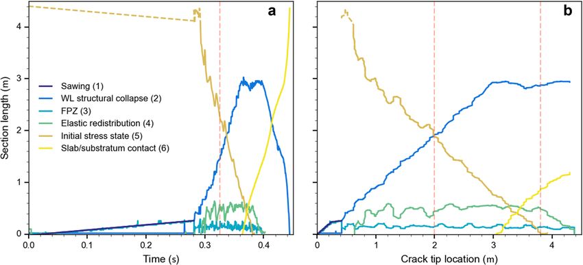
www.nature.com/scientificreports/
Figure 4. Mechanical parameters during crack propagation: snapshot at 0.344 s (after the start of the
simulation). (a) Average normal slab displacement in blue and average normal slab acceleration in green. (b)
Top view of the weak layer showing the bond states: in grey broken bonds, in red bonds that are breaking at
current time step. The blue line shows the breaking bond distribution along the length of the beam. (c) Normal
stress σzz and (d) shear stress τzx along the length of the beam. The light red box highlights the fracture process
zone (FPZ). The light yellow box highlights the part of the beam where the stresses are redistributed. The orange
vertical dashed lines indicate the start and end of the different sections (1, 2, 3, 4, and 5).
agreement between experimental and simulated PST (Fig. 3b). For all locations shown along the beam, the small
slab displacements (< 1 mm), which correspond to weak layer failure, were very closely reproduced. Normal
slab accelerations of subsets averaged over the height located at 2 and 3 m agreed well between experimental
and simulated PST (Fig. 3d). The large slab displacement in Fig. 3b corresponds to the weak layer; we note that
from 3.5 m the collapse height in the experiment was larger than in the simulation, in part due to a slab fracture
observed in the experiment (“Appendix 1”).
Crack speed along the PST beam was computed from experimental and simulation data based on the dif-
ferent metrics to define the crack tip location (Fig. 3c). The crack speed evolution revealed four phases. First,
during the cutting phase, the crack evolved at the same speed as the saw (1 m s−1 in the simulation). Second, a
transitional regime originated when the crack started to self-propagate and speed quickly increased over a dis-
tance of approximately 1.6 m until it reached a plateau. Third, up to the beam end, the crack speed was relatively
constant around 40 m s−1 in an apparent steady-state regime. Finally, in the last phase, the experimental crack
speed slightly increased, which does not show in the simulation.
Mechanical analysis of crack propagation. During the simulation, we tracked micro-mechanical
quantities: the position of bond-breaking events, normal displacement and acceleration as well as shear and
normal stresses at the top of the basal layer. The temporal evolution of these quantities revealed six distinct
sections during the fracture process (Fig. 4, labeled at the top from 1 to 5). In the following, we describe five of
the six sections for the situation shown in Fig. 4, i.e. when the crack tip is at about at 2.3 m, corresponding to a
simulation time of 0.344 s.
Scientific Reports | (2021) 11:11711 | https://doi.org/10.1038/s41598-021-90910-3 7
Vol.:(0123456789)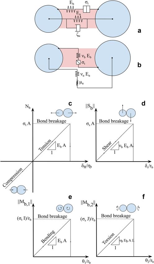
www.nature.com/scientificreports/
Figure 5. Temporal evolution of the length of six different fracture sections during a PST experiment as (a) a
function of time and (b) a function of crack tip location: (1) the sawing section, (2) the section where the weak
layer structure collapses, (3) the fracture process zone, (4) the elastic redistribution section, (5) the section
where the system is in its initial stress state, (6) the section where the slab and the substratum are in contact. The
light violet line corresponds to the sum of section lengths (2), (3) and (4). The orange vertical dashed line shows
the time when the crack speed reached a plateau with constant value of about 40 m s −1 (beyond 1.6 m in Fig. 3c).
(1) In the saw cut area, from 0 to 0.28 m, there are numerous broken bonds (grey dots in Fig. 4b) and the
stresses are low.
(2) From 0.28 to 2.12 m, there are many broken bonds and a few bonds breaking at the current time step (grey
dots and red dots in Fig. 4b, respectively); stresses remain low as the weak layer already fractured and the
slab is subsiding, but not yet resting on the crushed weak layer. A few stress peaks indicate that some highly
loaded contacts exist, but those disappear in the next time step confirming that the slab is still subsiding
and the weak layer structure is collapsing (see Supplementary Movie 2).
(3) The section from 2.12 to 2.3 m, represents the fracture process zone (FPZ; light red box in Fig. 4) where
most of the bonds are breaking in a narrow zone (Fig. 4b) and stresses reflect a mixed-mode loading state
(shear-compression) where the compressive (normal) stress is the dominant driver. The end of the FPZ
corresponds to the maximum normal stress. In the FPZ, the concave stress shape indicates that the weak
layer softens 35.
(4) From 2.3 to 2.87 m, the weak layer is mostly undamaged (light yellow box in Fig. 4) and stresses decrease
until reaching far-field values induced by gravity. In this zone, stresses are governed by elastic redistribu-
tion over a characteristic length scale Λ, depending on slab and weak layer elastic properties. Gaume
et al.22 suggested Λ to be given as follows: Λ = (Eslab’ Hslab Hwl/Gwl)1/2 where Eslab’ = Eslab/(1 – ν2) is the plane
stress elastic modulus of the slab and Gwl the weak layer shear modulus (Gwl = 0.21 MPa). In our case, the
theoretical value is Λ = 0.71 m, in reasonable agreement with the distance from the maximum stress to the
location where the stresses reach the initial state value (Fig. 4c, d; light yellow box; length: 0.57 m). Hence,
the elastic redistribution length is about twice the length of the FPZ.
(5) From 2.87 m to the end of the beam no bonds are breaking, the normal stress is equal to the gravitational
stress, and the shear stress is zero except towards the end of the beam where it becomes slightly positive
due to the free boundary condition (Fig. 4).
A sixth section appears later in the fracture process when slab comes to rest on the crushed weak layer. Stresses
in this contact area fluctuate and the acceleration becomes negative (deceleration) before reaching zero when slab
displacement stops (Supplementary Movie 2 and Fig. 3d). When the crack tip approaches the PST end (3.5 m),
the momentum at the free edge of the beam induces negative normal stress (tension) and causes bond breaking
in tension beyond the crack tip. Normal slab displacement and acceleration (Fig. 4a) exhibit specific trends for
each section: large displacement in the sawing and weak layer structural collapse sections (1, 2) with a nearly
constant acceleration of 2 m s−2, small displacements in the fracture process zone where the acceleration reaches
its maximum, no displacement in the elastic redistribution section where the acceleration decreases to zero, and
no displacements and accelerations in the intact section of the PST (Fig. 4a).
To investigate crack propagation from a micro-mechanical perspective, we investigated the evolution of the
six sections described above in more detail along the beam (Fig. 5; see also Supplementary Movie 2). The sawing
length (1) grew at the speed of the saw (1 m s−1) and stopped at the critical cut length ac. The section where the
weak layer structure collapses (2) started when the critical cut length was reached and grew linearly until the slab
came to rest on the crushed weak layer (at 0.362 s). Subsequently the length (2) fluctuated around (2.70 ± 0.05)
m until the weak layer was completely fractured (at 0.394 s) and decreased rapidly. The fracture process zone (3)
Scientific Reports | (2021) 11:11711 | https://doi.org/10.1038/s41598-021-90910-3 8
Vol:.(1234567890)www.nature.com/scientificreports/
increased linearly during the sawing phase and then fluctuated around (0.14 ± 0.04) m during crack propagation
until the crack tip reached the beam end. The length of the elastic redistribution section (4) was defined from the
maximum stress to the beginning of the slab motion (arbitrarily defined as the position where the normal slab
acceleration exceeds 0.85 m s−2). The elastic redistribution length (4) increased until the crack speed reached a
constant value. It fluctuated around (0.52 ± 0.05) m (Fig. 5, orange dashed lines) before decreasing again towards
the end of the experiment. The length of the section where the beam was in its initial state (5) decreased with
the same speed as the saw up to the critical cut length, and then decreased more rapidly with approximately a
constant speed until 0.38 s. The contact length (6) corresponded to the length where the slab rests on the crushed
weak layer. It increased almost linearly once the crack tip was at 2.98 m (0.361 s).
When the crack speed was in a steady state (orange dashed lines in Fig. 5), we observed a constant length of
the fracture process zone (3) and the elastic redistribution section (4). Figure 5b shows these section lengths as
function of crack tip position, the lengths (2), (3) and (4) clearly exhibit a plateau at the same time confirming
a steady state stress regime during crack propagation.
Discussion
We developed a 3-D discrete element model to investigate the micro-mechanical processes at play during crack
propagation in snow fracture experiments. Microscopic model properties were calibrated based on macroscopic
snowpack quantities using the method developed by Bobillier et al.18. The field data of a PST fracture experiment
was recorded during winter 2019 and analyzed with image correlation techniques11. The experiment provides
bulk snow properties and the displacement field during crack propagation and allows studying mixed-mode
failure of a porous weak snow layer. Our DEM model of the PST accurately reproduced the observed dynam-
ics of crack propagation including the structural collapse of the weak layer. Moreover, our PST model provides
insight into the micro-mechanics of the failure processes before and during self-sustained crack propagation.
Geometrical and mechanical properties retrieved from the PST experiment were used as input of our numeri-
cal model. However, as weak layer parameters cannot be measured in detail, the mechanical parameters of the
layers ( E, τ th ) were tuned to reproduce the experimental behavior. The comparison of the displacement fields
(normal and tangential) shows our model can reproduce the experimentally observed displacements and slab
acceleration (Fig. 3; Appendix 2). However, some discrepancies can be noted, in particular at both edges of the
PST experiment. Due to the very thick slab (H = 1.1 m), the edges of the PST were subject to high deformation,
very likely leading to plastic deformation. Furthermore, a slab fracture occurred at the far end of the PST (Appen-
dix 1). As in our model, the slab is purely elastic, there cannot be any non-recoverable deformation. The slab
fracture induced a large vertical movement causing a divergence between the displacement fields of experiment
and simulation. Whereas the slab fracture observed in the experiment influenced the final slab displacement,
it did not affect crack propagation behavior so that our analysis of the failure processes in the weak layer is not
affected either. A simulation including slab brittle fracture is provided in Appendix 1 and shows that the model
can also reproduce the complex interplay between weak layer and slab fracture.
For closing crack faces under compression (anticrack), the crack tip is not clearly defined and no formal
and well-accepted definition exists. Hence, we introduced four different metrics to determine the position of
the crack tip, based on slab displacement threshold, maximum normal slab acceleration, stress maxima and the
distribution of breaking bonds (Fig. 2). We then computed the crack speed based on these crack tip definitions,
resulting in very similar values (Fig. 3c). Over the length of the experiment, crack speeds exhibit two phases:
an initial transitional regime with rapidly increasing crack speed, a steady-state regime between 1.6 m and 4 m.
These phases were observed in both the numerical as well as the experimental PST.
The length of the column in our PST experiment is at least twice as long as previously reported column lengths
and should be sufficient for reaching a steady state propagation36. We showed that after 1.6 m the crack speed
starts to vary around a constant value. Even if the crack speed evolution suggests a steady state propagation, the
slab fracture observed in the experiment likely influenced crack propagation, casting some doubt on the validity
of this observation. Nevertheless, the experimental length combined with the uniform collapse height support
the interpretation that crack propagation reached a steady state. The mean value observed during the steady state
speed phase (approx. 40 m s−1) is of the same order of magnitude as previously reported propagation speeds9,37,38.
However, a direct quantitative comparison is hindered by the fact that previously reported propagation speeds
were primarily computed for relatively short PSTs (< 2 m) and speeds were averaged over the length of the beam.
Heierli39 proposed an analytical model and suggested that the crack, in the weak layer, occurs in the form of
g D
a localized disturbance zone propagating as a collapse wave with constant speed ch = 4 − 2h ρH . Here D is the
3
flexural rigidity D = 12E(slab H
1−ν2 )
, g the gravitational acceleration, h the collapse height, ρ the mean slab density, H
the slab thickness and ν the Poisson’s ratio. In the presented PST model, √ this bending wave would propagate with
ch = 40.9 m √s−1. For comparison, the slab longitudinal wave: cl = E/ρ = 183 m s−1, and the slab shear wave
speed: cs = G/ρ = 122m s−1. The formulation suggested by Heierli39 agrees well with the measured steady
state speed, longitudinal and shear wave speeds are much higher; nonetheless, we cannot easily interpret the
measured crack speed. A future sensitivity study may provide more insight.
The DEM model of the PST experiment allows insight into the micro-mechanical behavior of weak layer
failure. We suggest six sections to describe the crack dynamics during a PST experiment; (1) sawing, (2) weak
layer collapse, (3) fracture process zone, (4) elastic redistribution, (5) undisturbed (initial) stress state, and slab-
substratum contact (6). We looked into three of these sections in more detail: (2) The structural weak layer col-
lapse (crushing) where the stresses remain low and only a few bonds are breaking. (3) The fracture process zone
where the material softens and most of the bonds are breaking and where the stress is maximal. (4) The elastic
redistribution zone where the stresses are converging to the initial undistributed stress state and no bonds are
Scientific Reports | (2021) 11:11711 | https://doi.org/10.1038/s41598-021-90910-3 9
Vol.:(0123456789)www.nature.com/scientificreports/
breaking. During steady state propagation, we observed that these three sections travel along the beam keeping
their behavior, which is defined by the geometrical and mechanical properties (Fig. 5; Supplementary Movie 2).
Frame by frame, the stresses were analyzed and the results indicated a mixed-mode bond failure with a main
normal stress component (Supplementary Movie 2). We also noted (not shown) that the PST width does not
influence the crack tip morphology. Before reaching a steady state speed regime, we defined a transitional regime
where we observed a decrease in the normal stress and an increase of the shear stress component.
Gaume et al.15 introduced a 2-D DEM model of a PST experiment to study crack propagation. Their model
consisted of a single particle base layer, a triangular shape for the weak layer structure and a square particle
matrix for the slab layer. Their simple model was used to study the influence of mechanical parameters on crack
propagation. However, the simplistic layer representation precluded a detailed micro-mechanical analysis. The
model presented here overcomes this limitation and allows insight into the micro-mechanics, yet at the expense
of high computational cost. Still, to keep the computational cost reasonable (~hours to day), the particle radius
chosen does not represent single snow grains, but represents a mesoscale model of snow18. To permit this analy-
sis, we discretized the column length and the mesh size was driven by the particle size, which remains the main
model limitation. Observing the final slab state suggested the existence of plastic deformation and slab fracture.
By modifying slab tensile strength, we were able to reproduce the observed slab fracture (Appendix 1). However,
the contact law we use does not allow for non-recoverable slab deformation.
The experimental slab displacement exhibits high damping behavior when the slab comes into contact with
the broken weak layer (no slab bouncing). Our approach was to use a damping coefficient to dissipate slab kinetic
energy avoiding spurious oscillations, therefore, reproduce slab displacement, velocity and acceleration (Figure
supplement). In reality, this numerical damping may encompass different types of sources of energy dissipa-
tion that are not accounted yet, such as slab plastic hardening, mechanisms related to weak layer bond failure
(quasi-brittle softening behavior), or rate-dependent effects such as fast sintering. The accumulated strain energy
in weak layer bonds is released upon bond failure (perfectly brittle behavior) and leads to crack propagation.
Introducing a quasi-brittle softening contact model for the weak layer and allowing slab plastic deformation are
possible improvements to the physics of the model.
In this study, we only reproduced one single PST experiment performed in flat terrain. The availability of
the experimental data obtained with the correlation technique as well as the computational time to tune model
parameters were the key limiting factors preventing extensive model validation, which was not our primary
goal. Rather we focused on bond breaking evolution and stresses to provide new insights into the propagation
dynamics. These novel conceptual findings seem robust and well-founded in the model results. In the future,
we will explore model sensitivity on propagation behavior and exploit the micro-mechanical insights in view
of snow slab avalanche release modeling. We will focus on the effect of mechanical parameters: on the transient
acceleration regime and steady-state regime, and on the micro-mechanics such as the stress concentration and
bond breaking morphology. The influence of slope angle will also be studied to gain more insight into the ava-
lanche formation mechanism.
Conclusions
Understanding crack propagation behavior in the highly porous and anisotropic material snow is crucial to
appropriately model snow slab avalanche release. In this study, we reproduced a fracture mechanical field experi-
ment with a 3-D DEM simulation. The model results highlight the occurrence of a steady state in crack speed
and stress conditions for sufficiently long PSTs (> 4 m). In our case of closing-mode (anticrack) fracture, the
identification of the crack tip is not straightforward. Hence, we proposed four different methods to define the
crack tip that can be applied for experimental as well as simulated data. While the different methods yield dif-
ferent crack tip locations, they provide very similar values of crack speed. This finding suggests that previously
used displacement threshold methods on experimental data to derive crack speed are appropriate.
As our DEM approach allows insight into bond-breaking events and stresses, we suggest six sections to
describe the crack dynamics during a PST experiment. In particular, three distinct sections travel along the
beam while keeping their behavior during the steady state stress regime: weak layer structural collapse, fracture
process zone, and elastic redistribution. The detailed micro-mechanical analysis of stresses for weak layer fail-
ure suggests that the main drivers of crack propagation is the mixed mode stress concentration at the crack tip
(compression and shear).
In future, we will perform a parameter study to describe the drivers of crack speed at the slope scale leading
to avalanche release. The effects of slope angle and mechanical parameters on crack propagation will be studied
to eventually improve the prediction of avalanche size.
Appendix 1: Slab fracture
The horizontal displacement field reveals the occurrence of slab fractures despite the crack travelling to the far
end of the column. Figure 6a shows the normalized tangential displacement field in the final state of the experi-
mental PST. From the 0 to 2.6 m, at the top, we observed a color continuity; at 2.6 m, the color slightly jumps
from blue to yellow, which suggests a slab fracture stopped approximately 0.25 m below the top. At 3.15 m the
color jumps from light orange to red; this color jump clearly indicates a slab fracture and rigid body behavior
isolated from the rest of the beam. The location of the shallow, blurry slab fracture (2.6 m) corresponds to the
location where the simulated and experimental normal displacement behavior start to diverge (Fig. 3b). The
location of the second more distinct slab fracture (3.15 m) corresponds to the location where the simulated and
experimentally observed collapse height start to diverge (Fig. 3b). In the experiment, the collapse height is larger
possibly due to isolated rigid body behavior. We observed that the left and the right part of the beam kept its
tangential displacement at the end of the experiment, which suggests plasticity (Fig. 6b).
Scientific Reports | (2021) 11:11711 | https://doi.org/10.1038/s41598-021-90910-3 10
Vol:.(1234567890)www.nature.com/scientificreports/
Figure 6. (a) Experimental and (c) simulated slab horizontal displacement field at the end of the experiment.
Black dots in (c) indicate the positions of broken bonds and show the slab fracture. (b) Experimental and (d)
simulated temporal evolution of subsets of tangential displacements located at the top of the beam; colors
indicate horizontal location along the beam.
Figure 7. Comparison between observed and simulated displacements during PST experiment. (a) Temporal
evolution of the normal displacement averaged over the height of the beam. (b) Temporal evolution of subsets
of tangential displacements located at the top of the beam. (c) Temporal evolution of the normal acceleration.
(d) Temporal evolution of the tangential acceleration. The colors represent the horizontal location and the black
dashed lines the corresponding location for the simulated PST.
Scientific Reports | (2021) 11:11711 | https://doi.org/10.1038/s41598-021-90910-3 11
Vol.:(0123456789)www.nature.com/scientificreports/
For the simulation shown in Fig. 7c, the normalized tangential displacement field in the final state of the
simulated experiment, we relaxed the assumption of infinite slab strength and introduced a vertical linear tensile
strength gradient within the simulated slab to reproduce the slab fracture behavior (top: σslab
th = 3 kPa, bottom:
th = 3.4 kPa). The positions of the broken bonds indicate that the observed positions of the slab fractures were
σslab
qualitatively well-reproduced (black dots in Fig. 6c). Figures 6b and 7d show the temporal evolution of subsets of
tangential displacements located at the top of the beam. From 0 to 2.5 m, i.e. up to 0.36 s, the experimental and
simulated data show similar behavior. After 0.36 s, the simulated tangential displacement tends to return to its
initial state, while in the experiment the deformation is not recovered. Figure 6d shows a clear change in behav-
ior when the slab fractures occurred, from 3 m to the end of the column the subsets show a different behavior
than at the beginning of the column. This behavior is well reproduced by the simulation until 0.38 s when the
simulated displacements return to its initial state, while in the experiment the displacements are not recovered.
However, unlike to the experiment, in the simulation the beam tends to recover its deformation. While adding
slab strength allowed reproducing the slab fractures, the contact model does not account for plasticity. Hence,
in the simulation, we cannot reproduce the final state of deformation observed in the experiment.
Appendix 2: Comparison of slab behavior
Similar to Figs. 3b, d and 7a show the temporal evolution of the normal displacement of the slab and Fig. 7c the
temporal evolution of the slab normal acceleration and (d) the slab tangential acceleration. In addition, Fig. 7b
shows the temporal evolution of the tangential (horizontal) displacement of the slab. Slab behavior observed in
the experiment is well reproduced by the simulation (dashed lines); the main differences appear after the so-called
touchdown when the simulated tangential displacements return to its initial state, whereas the displacements
in the experiment exhibit non-recoverable deformation (plasticity). This phenomenon is accentuated at the free
edges of the beam and by slab fractures (Appendix 1).
Appendix 3: Parallel bond contact model
See Fig. 8.
Scientific Reports | (2021) 11:11711 | https://doi.org/10.1038/s41598-021-90910-3 12
Vol:.(1234567890)www.nature.com/scientificreports/
Figure 8. PFC3D parallel bond model (PBM) representation and its bonded behavior. (a) Normal mechanical
parameter bonded and unbonded, where Eb represents the bond elastic modulus, σt the tensile strength, Eu the
contact elastic modulus and ζu the contact damping ratio. (b) Shear mechanical parameter bond and unbonded,
where Eb represents the bond elastic modulus, σs the shear strength, Eu the contact elastic modulus, νb the bond
Poisson’s ratio, νu the contact Poisson’s ratio and µu the friction coefficient. To reduce the number of variables
we assume Eu = Eb Eparticle, σs = σt σbond th and ν = ν . (c) Bond normal force N as a function of the
u b b
normal interpenetration δn scaled by the bond radius rb. (d) Bond shear force Sb as a function of tangential
interpenetration δs scaled by the bond radius rb. (e) Bond-bending moment Mb,1 as a function of bending
rotation θ1 scaled by the bond radius rb. (f) Torsion moment Mb,2 as a function of twist rotation θ2 scaled by
the bond radius rb.
Received: 14 February 2021; Accepted: 4 May 2021
References
1. Desrues, J., Lanier, J. & Stutz, P. Localization of the deformation in tests on sand sample. Eng. Fract. Mech. 21, 909–921. https://
doi.org/10.1016/0013-7944(85)90097-9 (1985).
2. Barraclough, T. et al. Propagating compaction bands in confined compression of snow. Nat. Phys. 13, 272–275. https://doi.org/10.
1038/nphys3966 (2017).
3. Gaume, J., Gast, T., Teran, J., van Herwijnen, A. & Jiang, C. Dynamic anticrack propagation in snow. Nat. Commun. 9, 3047. https://
doi.org/10.1038/s41467-018-05181-w (2018).
4. Walters, D. J. & Adams, E. E. Quantifying anisotropy from experimental testing of radiation recrystallized snow layers. Cold Reg.
Sci. Technol. 97, 72–80. https://doi.org/10.1016/j.coldregions.2013.09.014 (2014).
5. McClung, D. M. Shear fracture precipitated by strain softening as a mechanism of dry slab avalanche release. J. Geophys. Res. 84,
3519–3526. https://doi.org/10.1029/JB084iB07p03519 (1979).
6. Schweizer, J., Jamieson, J. B. & Schneebeli, M. Snow avalanche formation. Rev. Geophys. 41, 1016. https://doi.org/10.1029/2002R
G000123 (2003).
Scientific Reports | (2021) 11:11711 | https://doi.org/10.1038/s41598-021-90910-3 13
Vol.:(0123456789)www.nature.com/scientificreports/
7. Gauthier, D. & Jamieson, J. B. Towards a field test for fracture propagation propensity in weak snowpack layers. J. Glaciol. 52,
164–168. https://doi.org/10.3189/172756506781828962 (2006).
8. Sigrist, C., Schweizer, J., Schindler, H. J. & Dual, J. Measurement of fracture mechanical properties of snow and application to dry
snow slab avalanche release. Geophys. Res. Abstr. 8, 08760 (2006).
9. van Herwijnen, A. & Jamieson, B. High-speed photography of fractures in weak snowpack layers. Cold Reg. Sci. Technol. 43, 71–82.
https://doi.org/10.1016/j.coldregions.2005.05.005 (2005).
10. van Herwijnen, A. et al. Estimating the effective elastic modulus and specific fracture energy of snowpack layers from field experi-
ments. J. Glaciol. 62, 997–1007. https://doi.org/10.1017/jog.2016.90 (2016).
11. Bergfeld, B. et al. Dynamic crack propagation in weak snowpack layers: Insights from high-resolution, high-speed photography.
Cryosphere Discuss. https://doi.org/10.5194/tc-2020-360 (2020).
12. Benedetti, L., Gaume, J. & Fischer, J. T. A mechanically-based model of snow slab and weak layer fracture in the Propagation Saw
Test. Int. J. Solids Struct. 158, 1–20. https://doi.org/10.1016/j.ijsolstr.2017.12.033 (2019).
13. Chiaia, B. M., Cornetti, P. & Frigo, B. Triggering of dry snow slab avalanches: stress versus fracture mechanical approach. Cold
Reg. Sci. Technol. 53, 170–178. https://doi.org/10.1016/j.coldregions.2007.08.003 (2008).
14. Gaume, J., Chambon, G., Eckert, N. & Naaim, M. Influence of weak-layer heterogeneity on snow slab avalanche release: application
to the evaluation of avalanche release depths. J. Glaciol. 59, 423–437. https://doi.org/10.3189/2013JoG12J161 (2013).
15. Gaume, J., van Herwijnen, A., Chambon, G., Birkeland, K. W. & Schweizer, J. Modeling of crack propagation in weak snowpack
layers using the discrete element method. Cryosphere 9, 1915–1932. https://doi.org/10.5194/tc-9-1915-2015 (2015).
16. Rosendahl, P. L. & Weissgraeber, P. Modeling snow slab avalanches caused by weak-layer failure—Part 1: Slabs on compliant and
collapsible weak layers. Cryosphere 14, 115–130. https://doi.org/10.5194/tc-14-115-2020 (2020).
17. Rosendahl, P. L. & Weissgraeber, P. Modeling snow slab avalanches caused by weak-layer failure—Part 2: Coupled mixed-mode
criterion for skier-triggered anticracks. Cryosphere 14, 131–145. https://doi.org/10.5194/tc-14-131-2020 (2020).
18. Bobillier, G. et al. Micromechanical modeling of snow failure. Cryosphere 14, 39–49. https://d oi.o
rg/1 0.5 194/t c-1 4-3 9-2 020 (2020).
19. Hagenmuller, P., Chambon, G. & Naaim, M. Microstructure-based modeling of snow mechanics: a discrete element approach.
Cryosphere 9, 1969–1982. https://doi.org/10.5194/tc-9-1969-2015 (2015).
20. Mede, T., Chambon, G., Hagenmuller, P. & Nicot, F. Snow failure modes under mixed loading. Geophys. Res. Lett. 45, 13351–13358.
https://doi.org/10.1029/2018GL080637 (2018).
21. Johnson, J. B. A preliminary numerical investigation of the micromechanics of snow compaction. Ann. Glaciol. 26, 51–54 (1998).
22. Gaume, J., van Herwijnen, A., Chambon, G., Wever, N. & Schweizer, J. Snow fracture in relation to slab avalanche release: critical
state for the onset of crack propagation. Cryosphere 11, 217–228. https://doi.org/10.5194/tc-11-217-2017 (2017).
23. Sigrist, C. & Schweizer, J. Critical energy release rates of weak snowpack layers determined in field experiments. Geophys. Res.
Lett. 34, L03502. https://doi.org/10.1029/2006GL028576 (2007).
24. Greene, E. et al. Snow, Weather, and Avalanches: Observation Guidelines for Avalanche Programs in the United States. 3rd edn,
(American Avalanche Association, 2016).
25. Schneebeli, M. & Sokratov, S. A. Tomography of temperature gradient metamorphism of snow and associated changes in heat
conductivity. Hydrol. Process. 18, 3655–3665. https://doi.org/10.1002/hyp.5800 (2004).
26. Cundall, P. A. & Strack, O. D. L. A discrete numerical model for granular assemblies. Geotechnique 29, 47–65. https://doi.org/10.
1680/geot.1979.29.1.47 (1979).
27. Potyondy, D. O. & Cundall, P. A. A bonded-particle model for rock. Int. J. Rock Mech. Min. 41, 1329–1364. https://doi.org/10.
1016/j.ijrmms.2004.09.011 (2004).
28. Löwe, H., Egli, L., Bartlett, S., Guala, M. & Manes, C. On the evolution of the snow surface during snowfall. Geophys. Res. Lett. 34,
L21507. https://doi.org/10.1029/2007GL031637 (2007).
29. Kadau, D. & Herrmann, H. J. Density profiles of loose and collapsed cohesive granular structures generated by ballistic deposition.
Phys. Rev. E 83, 031301. https://doi.org/10.1103/PhysRevE.83.031301 (2011).
30. Benn, D. Fabric shape and the interpretation of sedimentary fabric data. J. Sediment. Res. 64, 910–915. https://doi.org/10.1306/
D4267F05-2B26-11D7-8648000102C1865D (1994).
31. Srivastava, P. K., Chandel, C., Mahajan, P. & Pankaj, P. Prediction of anisotropic elastic properties of snow from its microstructure.
Cold Reg. Sci. Technol. 125, 85–100. https://doi.org/10.1016/j.coldregions.2016.02.002 (2016).
32. Savitzky, A. & Golay, M. J. E. Smoothing and differentiation of data by simplified least squares procedures. Anal. Chem. 36,
1627–1639. https://doi.org/10.1021/ac60214a047 (1964).
33. Shapiro, L. H., Johnson, J. B., Sturm, M. & Blaisdell, G. L. Snow mechanics—Review of the state of knowledge and applications.
Report No. CRREL Report 97-3, 43 (US Army Cold Regions Research and Engineering Laboratory, Hanover, NH, USA, 1997).
34. Jamieson, J. B. & Johnston, C. D. Evaluation of the shear frame test for weak snowpack layers. Ann. Glaciol. 32, 59–68. https://doi.
org/10.3189/172756401781819472 (2001).
35. Bazant, Z. P. & Planas, J. Fracture and size effect in concrete and other quasibrittle materials. (CRC Press, 1998).
36. van Herwijnen, A., Schweizer, J. & Heierli, J. Measurement of the deformation field associated with fracture propagation in weak
snowpack layers. J. Geophys. Res. 115, F03042. https://doi.org/10.1029/2009JF001515 (2010).
37. van Herwijnen, A. et al. in Proceedings ISSW 2016. International Snow Science Workshop, Breckenridge CO, U.S.A., 3–7 October
2016. (ed E. Greene) 397–404.
38. Birkeland, K. W., van Herwijnen, A., Reuter, B. & Bergfeld, B. Temporal changes in the mechanical properties of snow related to
crack propagation after loading. Cold Reg. Sci. Technol. 159, 142–152. https://doi.org/10.1016/j.coldregions.2018.11.007 (2019).
39. Heierli, J. Solitary fracture waves in metastable snow stratifications. J. Geophys. Res. 110, F02008. https://doi.org/10.1029/2004J
F000178 (2005).
Acknowledgements
GB has been supported by a Grant from the Swiss National Science Foundation (200021_16942). We thank the
anonymous reviewers for their constructive reviews that helped us to improve our paper.
Author contributions
J.S. and A.H. conceived this study, in discussion with J.G. G.B. developed the 3D DEM model of the PST and
made the simulations with help from J.G.. B.B. and A.H. performed the field experiment and analyzed the
experimental data. All authors contributed to the interpretation of the results. G.B. prepared the manuscript
with contributions from all co-authors.
Competing interests
The authors declare no competing interests.
Scientific Reports | (2021) 11:11711 | https://doi.org/10.1038/s41598-021-90910-3 14
Vol:.(1234567890)You can also read