Nicaragua Canal Project Description - December 2014 / A
←
→
Page content transcription
If your browser does not render page correctly, please read the page content below
December 2014 / A

Nicaragua Canal Project Description
Nicaragua Canal Project Description                                                                                                       December 2014 / A

TABLE OF CONTENTS

1.     Introduction ........................................................................................................................................... 1
2.     General Project Description .................................................................................................................. 1
3.     Project Facilities.................................................................................................................................... 4
     3.1      Canal Facilities.............................................................................................................................. 4
     3.2      Ports ............................................................................................................................................ 28
     3.3      Associated Project Facilities ....................................................................................................... 29
4.     Project Construction............................................................................................................................ 36
     4.1      Schedule ...................................................................................................................................... 36
     4.2      Workforce ................................................................................................................................... 38
     4.3      Equipment ................................................................................................................................... 40
     4.4      Materials and Supplies ................................................................................................................ 42
     4.5      Infrastructure ............................................................................................................................... 43
     4.6      General Construction Principles ................................................................................................. 44
     4.7      Construction Sequence ................................................................................................................ 53
5.     Project Operations ............................................................................................................................... 72
     5.1      Ship Transit ................................................................................................................................. 72
     5.2      Power Requirements ................................................................................................................... 74
     5.3      Water Requirements.................................................................................................................... 74
     5.4      Salinity Management .................................................................................................................. 74
     5.5      Workforce Requirements ............................................................................................................ 76
     5.6      Security Requirements ................................................................................................................ 76
     5.7      Public Boat Use Policy ............................................................................................................... 76
     5.8      Ferry Service ............................................................................................................................... 76
     5.9      Maintenance Dredging ................................................................................................................ 76
     5.10     Port Operations ........................................................................................................................... 77
6.     Proposed Embedded Controls ............................................................................................................. 77
7.     References ........................................................................................................................................... 78

                                                                                i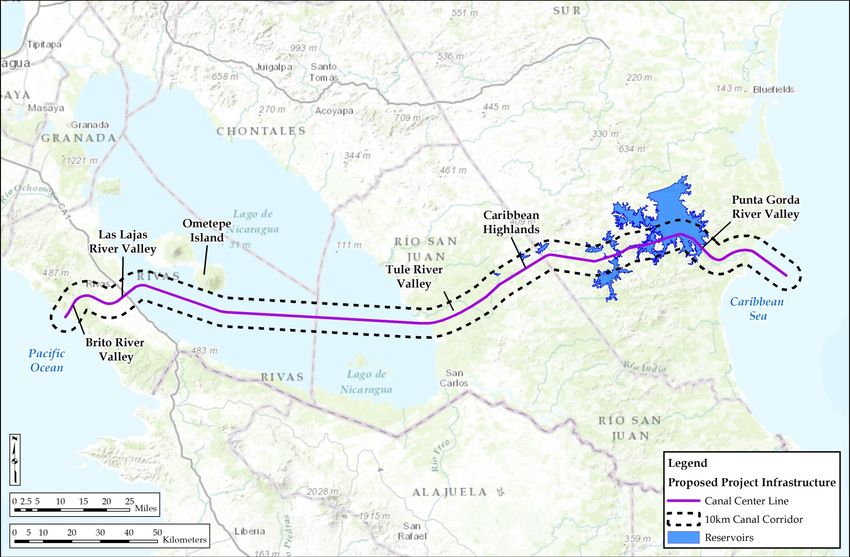
Nicaragua Canal Project Description                                                                                                       December 2014 / A

LIST OF TABLES

Table 3.1-1: Canal Dimensions..................................................................................................................... 5
Table 3.1-2: Target Vessel Dimensions ........................................................................................................ 7
Table 3.1-3: Earthwork Quantities by Type and Canal Segment................................................................ 16
Table 3.1-4: Excavated Material Placement Area Characteristics .............................................................. 17
Table 3.1-5: Lago de Nicaragua Dredge Disposal Areas ............................................................................ 22
Table 3.1-6: Marine Dredge Disposal Areas .............................................................................................. 25
Table 3.3-1: Basic Road Design Parameters ............................................................................................... 30
Table 3.3-2: Transmission Lines................................................................................................................. 34
Table 3.3-3: Aggregate Quarries................................................................................................................. 34
Table 3.3-4: Borrow Areas ......................................................................................................................... 34
Table 3.3-5: Canal Construction Crossings and Mitigation ........................................................................ 36
Table 4.3-1: Summary of Main Construction Equipment, Specification, and Quantity ............................. 41
Table 4.4-1: Construction Materials and Supplies ...................................................................................... 42
Table 4.4-2: Requisite Amount by year of Main Construction Building Materials .................................... 43
Table 4.6-1: Drill and Blast Design Parameters ......................................................................................... 47
Table 5.1-1: Canal de Nicaragua Freight Traffic Prediction by Year (number of transits) ........................ 72
Table 5.3-1: Project Operations Water Use ................................................................................................ 74
Table 5.4-1: Estimation of Effectiveness of Mitigating Project Measures including Indicative Uncertainty
Ranges ......................................................................................................................................................... 75
Table 6-1: Embedded Controls Identified for Construction and Operation ................................................ 77

                                                                                ii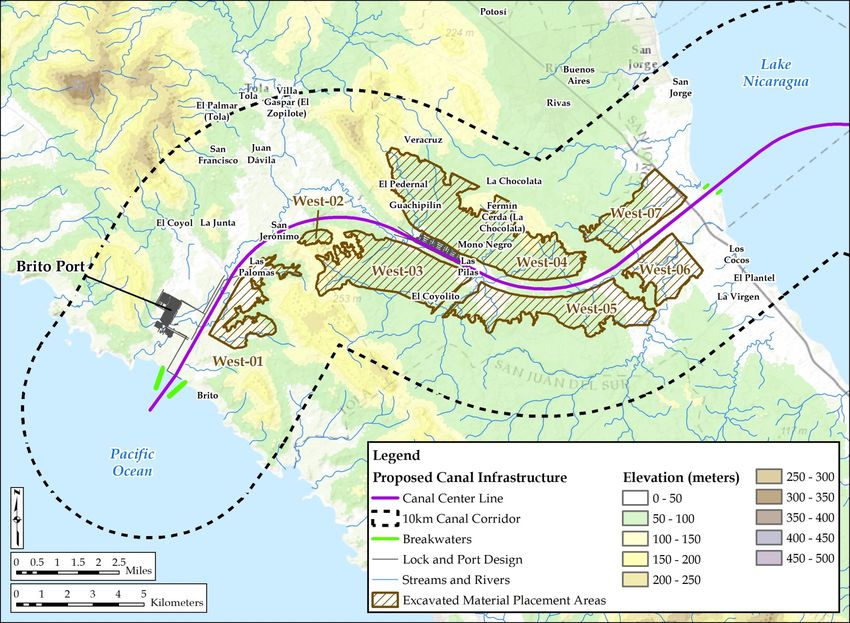
Nicaragua Canal Project Description                                                                                              December 2014 / A

LIST OF FIGURES

Figure 2-1: Project Location ......................................................................................................................... 2
Figure 2-2: Canal Cross Section (200 Vertical Exaggeration)...................................................................... 3
Figure 3.1-1: Canal Segmentation Landscape .............................................................................................. 6
Figure 3.1-2: Generic Batter Slopes .............................................................................................................. 9
Figure 3.1-3: Schematics of Water Level Change ...................................................................................... 11
Figure 3.1-4: Concept Lock with 3 Chambers and 9 Water Saving Basins ................................................ 12
Figure 3.1-5: Brito Lock Location (Zoomed Out) ...................................................................................... 12
Figure 3.1-6: Brito Lock Location (Zoomed In) ......................................................................................... 13
Figure 3.1-7: Camilo Lock Location and Plant View (Zoomed Out) ......................................................... 14
Figure 3.1-8: Detail of Camilo Lock with Associated Dam Structure (Zoomed In) .................................. 15
Figure 3.1-9: Canal Excavation Volumes by Station .................................................................................. 17
Figure 3.1-10: West Canal EMPAs............................................................................................................. 19
Figure 3.1-11: East Canal EMPAs .............................................................................................................. 20
Figure 3.1-12: Lago de Nicaragua Dredge Disposal Areas ........................................................................ 21
Figure 3.1-13: Example of a Confined Disposal Facility (CDF) ................................................................ 23
Figure 3.1-14: Typical Cross Section of a Confined Disposal Facility (CDF) Dike .................................. 24
Figure 3.1-15: Typical Cross Section of the Breakwater Structures ........................................................... 26
Figure 3.1-16: Pacific Entrance Breakwater and Brito Port ....................................................................... 27
Figure 3.1-17: Caribbean Entrance Breakwaters and Aguila Port .............................................................. 28
Figure 3.3-1: Proposed PanAmerican Highway Cable-Stayed Bridge Profile ........................................... 30
Figure 3.3-2: Cross-section of Public Roads .............................................................................................. 31
Figure 3.3-3: Cross-section of Maintenance Road...................................................................................... 32
Figure 3.3-4: Proposed Electrical Transmission Towers ............................................................................ 33
Figure 4.1-1: General Construction Schedule ............................................................................................. 37
Figure 4.6-1: Topsoil Stripping Example ................................................................................................... 45
Figure 4.6-2: Free Dig Example ................................................................................................................. 46
Figure 4.6-3: Drill and Blast Examples ...................................................................................................... 46
Figure 4.6-4: Assumed Blasting Percentage by Horizon ............................................................................ 47
Figure 4.6-5: Wet and Dry Blasting Percentage by Horizon ...................................................................... 48
Figure 4.6-6: Graphic of Benched Excavation within Canal Footprint ...................................................... 48
Figure 4.6-7: Truck and Excavator Conceptual Configuration ................................................................... 49
Figure 4.6-8: Excavated Material Placement .............................................................................................. 50

                                                                          iii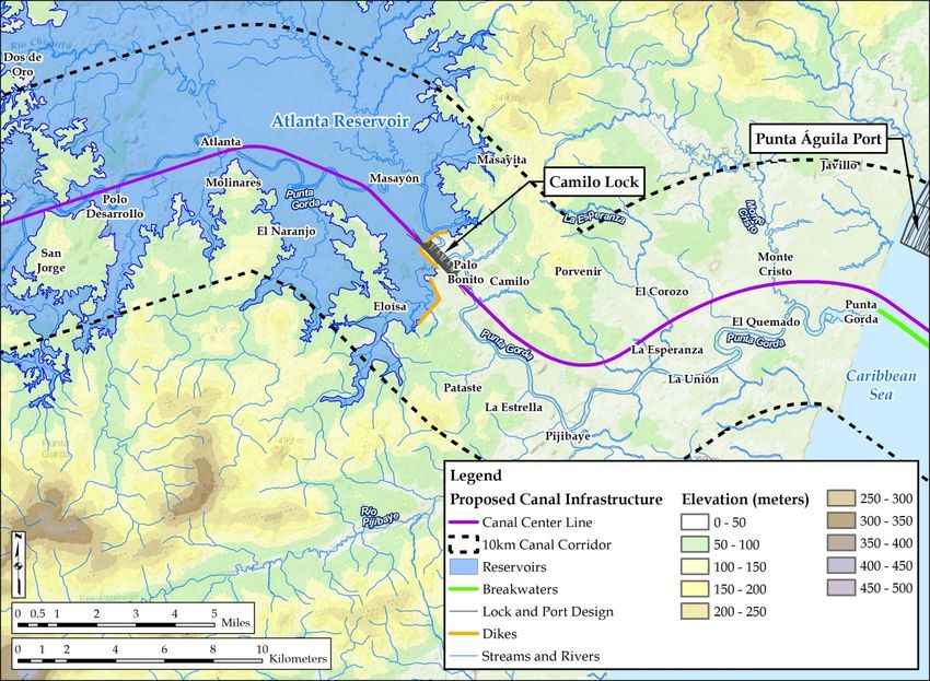
Nicaragua Canal Project Description                                                                                                December 2014 / A

Figure 4.6-9: EMPA Reclamation Concept ................................................................................................ 51
Figure 4.6-10: Drop Structures ................................................................................................................... 52
Figure 4.7-1: West Canal Excavation Strategy ........................................................................................... 57
Figure 4.7-2: Year 1 West Canal Dredge Excavation ................................................................................. 58
Figure 4.7-3: Year 1 West Canal Dry (Skim) Excavation .......................................................................... 59
Figure 4.7-4: Year 2 West Canal Activities between Stations 5 and 14 Kilometers .................................. 60
Figure 4.7-5: Year 2 West Canal Activities between Stations 14 and 25 Kilometers ................................ 61
Figure 4.7-6: Year 3 West Canal Activities between Stations 5 and 14 Kilometers .................................. 62
Figure 4.7-7: Year 3 West Canal Activities between Stations 14 and 25 Kilometers ................................ 62
Figure 4.7-8: Year 4 West Canal Activities between Stations 5 and 14 Kilometers .................................. 63
Figure 4.7-9: Year 4 Inland Dredging ......................................................................................................... 64
Figure 4.7-10: Year 5 West Canal Activities .............................................................................................. 65
Figure 4.7-11: East Canal Excavation Strategy .......................................................................................... 67
Figure 4.7-12: Stage 2 ................................................................................................................................. 69
Figure 4.7-13: Stage 3 ................................................................................................................................. 70

                                                                            iv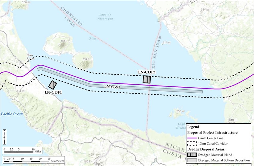
Nicaragua Canal Project Description                                        December 2014 / A

ACRONYMS AND ABBREVIATIONS

 CDF                    confined disposal facility
 CRB                    Caribbean side
 CRCC                   China Railway Construction Corporation
 DWT                    Dry Weight Tonnage
 EBRD                   European Bank for Reconstruction and Development
 EMPA                   Excavated Material Placement Area
 ERM                    Environmental resources Management
 ESIA                   Environmental and Social Impact Assessment
 g/cc                   grams per centimeter
 H                      hours
 ha                     hectare
 IFC                    International Finance Corporation
 kg/m3                  kilogram per cubic meter
 km                     kilometer
 km2                    square kilometers
 kW                     kilowatt
 kV                     kilovolt
 L                      liter
 m2                     square meters
 m3                     cubic meters
 m3/s                   cubic meters per second
 MARENA                 Ministerio del Ambiente y los Recursos Naturales
 mm                     millimeter
 Mm3                    Million cubic meters
 MW                     megawatts
 NA                     not applicable
 PCF                    Pacific side
 RAP                    Resettlement Action Plan
 SIN                    National Interconnected System
 SNT                    Sistema Nacional de Transmisión
 TEU                    twenty-foot equivalent units
 TOT                    total
 ULBC                   ultra-large bulk carriers
 USACE                  U.S. Army Corp of Engineers
 VLCC                   very large crude carriers

                                                    v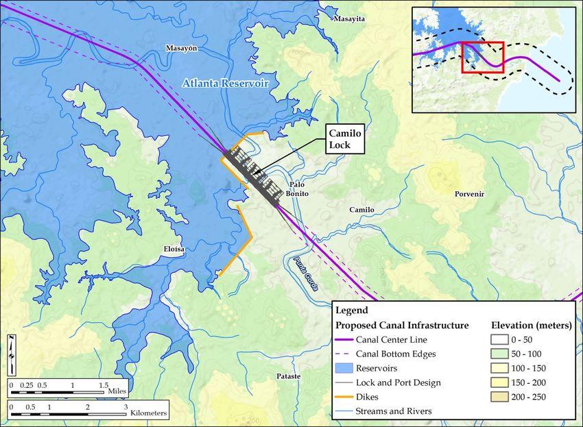
Nicaragua Canal Project Description                                     December 2014 / A

                                      -Page Intentionally Left Blank-

                                                    vi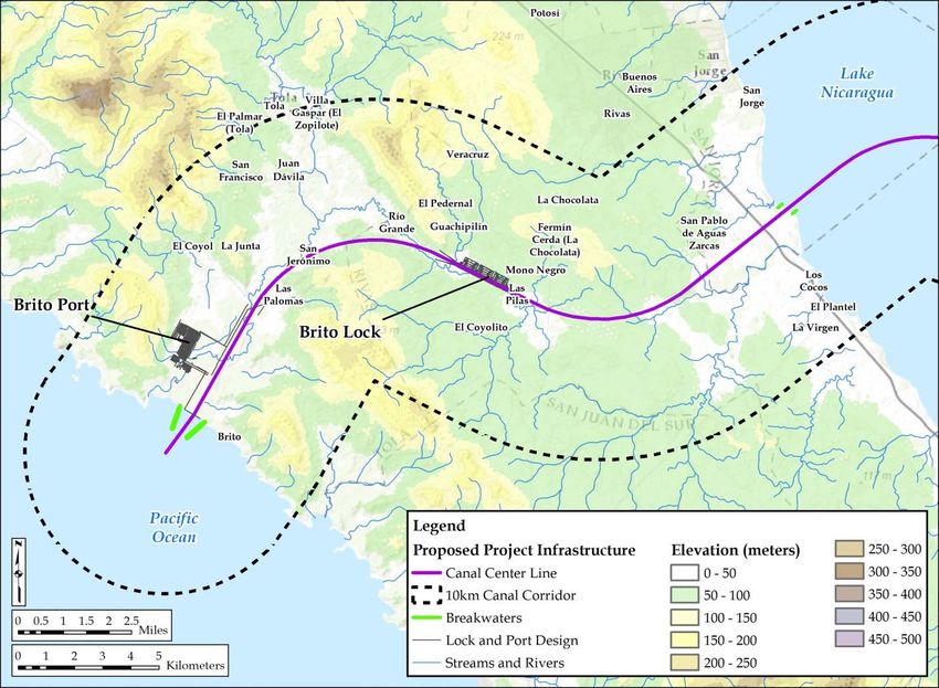
Nicaragua Canal Project Description December 2014 / A
1. INTRODUCTION
The Canal de Nicaragua (Project) is a major infrastructure project with the potential to transform global
trade and make Nicaragua a major center for transport and global logistics. The Project would be one of
the largest civil works projects ever undertaken. This Project Description is being released by HKND to
inform the Government of Nicaragua, affected communities, and other stakeholders about the current
status of Project design. Engineering studies are still on-going that may affect aspects of this Project
Design, as may stakeholder recommendations, but at this point, this paper describes the current Project
Description. Comments on this Project Description can be submitted via email to Environmental
Resources Management (ERM) at Nicaragua.Canal@erm.com.
The Project facilities are described below in as much detail as is available at this stage of the Project
design. The following Project Description relies heavily on preliminary engineering prepared by China
Railway Construction Corporation (CRCC)/ChangJiang (overall Project technical feasibility, concept
design, and engineering), MEC (earthworks strategy and engineering), and SBE/Deltares (lock design and
operations, freshwater availability, and salinity management). Additional engineering design is needed to
firmly quantify project impacts and finalize appropriate mitigation measures before an Environmental and
Social Impact Assessment (ESIA) can be completed.
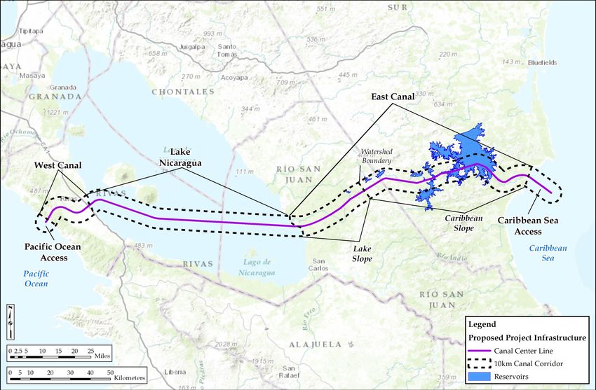
2. GENERAL PROJECT DESCRIPTION
The Project would be located in southern Nicaragua. It would traverse the country from the Pacific
shoreline near Brito, up the Rio Brito valley, over the continental divide, and down the Rio Las Lajas
valley to Lago de Nicaragua approximately 4 kilometers south of the town of San Jorge. It would then
cross Lago de Nicaragua approximately 4 kilometers south of the Isla de Ometepe, reaching the eastern
Lago de Nicaragua shoreline about 8 kilometers south of the town of San Miguelito. It would then move
up the Rio Tule stream valley and over the Caribbean highlands, with a maximum elevation along the
canal alignment of 224 meters. It would then traverse down the Rio Punta Gorda valley to the Caribbean
shoreline about 1 kilometer north of the mouth of the Rio Punta Gorda (see Figures 2-1 and 2-2).
1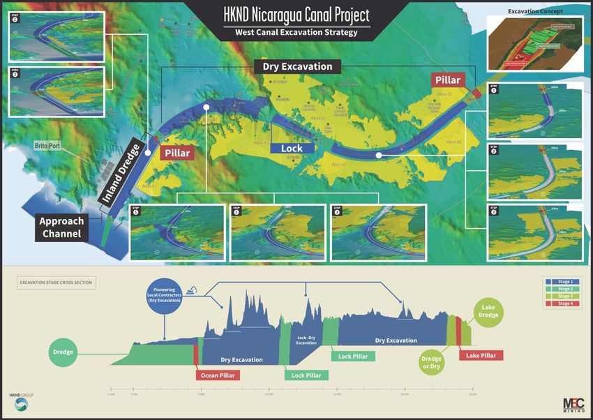
Nicaragua Canal Project Description                                  December 2014 / A

                                      Figure 2-1: Project Location

                                                   2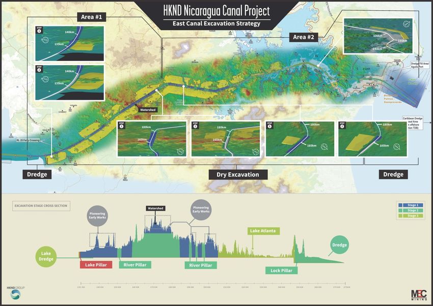
Nicaragua Canal Project Description                                                                 December 2014 / A

                                      Figure 2-2: Canal Cross Section (200 Vertical Exaggeration)

                                                                   3
Nicaragua Canal Project Description December 2014 / A
3. PROJECT FACILITIES
The Project includes the following facilities:
The canal; two locks and associated impoundments upstream; dredge disposal areas and excavated
material placement areas; a dike; a stand-alone dam; and breakwaters/training walls at the canal’s
Pacific, Caribbean, and Lago de Nicaragua entrances;
Ports at the canal’s Pacific and Caribbean entrances;
Associated Project Facilities, including transport improvements (e.g., access and maintenance roads, a
bridge for the Pan-American Highway over the Canal, and a ferry); power generating and
transmission facilities to deliver the power required to operate the canal; and two cement plants and
associated aggregate quarries; and minor improvements to the existing Corinto and Bluefield ports.
A detailed Project Map is provided for both paper and electronic copies of this Project Description
document.
Other facilities have been proposed, including a Free Trade Zone and associated commercial
developments, tourist hotels, and an airport. Construction of these facilities would begin when the canal
construction is advanced, which is 5 or more years in the future. Further, little information exists at this
time to allow a full impact assessment of these facilities. For these reasons, these other facilities are not
included as part of the proposed Project
3.1 CANAL FACILITIES
3.1.1 Canal Design
3.1.1.1 Canal Length
The canal will extend 259.4 kilometers from the Pacific shoreline, across Lago de Nicaragua, to the
Caribbean shoreline. The Project would also require dredging of marine approaches to achieve required
shipping depths of approximately 1.7 kilometers in the Pacific Ocean and 14.4 kilometers in the
Caribbean Sea. Combined, these create a total length of about 275.5 kilometers.
This Project Description and some of its figures reference “stations” along the canal. These stations
reflect locations along the centerline of the canal and are shown in 5 kilometer intervals starting at the
Pacific coast (Station 0) and extending to the Caribbean coast (Station 259.4).
For purposes of this Project Description, the canal is divided into five segments (see Figure 3.1-1):
Pacific Ocean – the marine approach from the outer limit of required dredging to the Pacific
shoreline (1.7 kilometers).
West Canal – from the Pacific shoreline to Lago de Nicaragua, including the West or Brito Lock and
the Brito Port (25.9 kilometers). This segment is sometimes subdivided into:
o Pacific Slope – the portion that drains directly to the Pacific Ocean (18.4 kilometers); and
o Lake Slope – the portion that drains to Lago de Nicaragua (7.5 kilometers).
4Nicaragua Canal Project Description December 2014 / A
Lago de Nicaragua – from the western to the eastern shorelines of Lago de Nicaragua
(106.8 kilometers).
East Canal – from Lago de Nicaragua to the Caribbean shoreline, including the East or Camilo Lock
(126.7 kilometers). This segment is sometimes subdivided into:
o Lake Slope – the portion that drains to Lago de Nicaragua (37.4 kilometers); and
o Caribbean Slope – the portion that drains directly to the Caribbean Sea via the Rio Punta Gorda
(89.3 kilometers).
Caribbean Sea – the marine approach from the outer limit of required dredging to the Caribbean
shoreline, including the Aguila Port (14.4 kilometers).
The various canal segments, to include typical widths and design canal bottom elevations, are presented
in Table 3.1-1.
Table 3.1-1: Canal Dimensions
Design
Bottom Typical Canal
Canal Sections Length (km) Minimum
Elevation Bottom Width
Depth
Pacific Ocean 1.7 -30.2 m 29.0 m 280 m
Pacific coast to the Brito Lock 12.5 -30.2 m 29.0 m 280 m
Brito Lock to Lake Nicaragua 13.4 3.25 m 26.9 m 230 m
Lago de Nicaragua1 106.8 1.75 m 28.4 m 280 m
Lake Nicaragua to Camilo Lock 105.6 3.25 m 26.9 m 230 m
Camilo Lock to the Caribbean coast 21.1 -29.8 m 29.0 m 280 m
Caribbean Sea 14.4 -29.8 m 29.0 m 280 m
Total length 275.5 NA NA NA
km = kilometers; m = meters; NA = not applicable
1
Average water elevation in Lago de Nicaragua is approximately 31.3 meters, and the canal’s operating range is from elevation
30.2 meters to 33.0 meters.
2
Some optimization might be required during detailed design of the canal.
5Nicaragua Canal Project Description December 2014 / A
Figure 3.1-1: Canal Segmentation Landscape
6Nicaragua Canal Project Description December 2014 / A
3.1.1.2 Target Vessel
The canal design is based on The World Association for Waterborne Transport Infrastructure (PIANC)
report Approach Channels, A Guide for Design (PIANC 1997). The critical component in the design of
the waterway is the selection of the "target" vessel. In evaluating the waterway maneuvering parameters,
the target vessel is normally the largest vessel that the waterway is expected to accommodate safely and
efficiently.
The parameters required for the target vessel are:
Length
Beam
Maximum draft
Speed
As discussed in Chapter 1.0, Introduction, the Canal de Nicaragua is intended to primarily provide transit
for ships too large for the expanded Panama Canal. The canal cross section is dictated by these “target
vessel” it is intended to accommodate. The typical dimensions of these target vessels are provided in
Table 3.1-2. The largest container ships are currently 19,300 twenty-foot equivalent units (TEU)
containers, so the 25,000 TEU ship dimensions are estimates. The Canal de Nicaragua as constructed is
itself likely to influence the actual dimensions of the largest ships, as has the Panama Canal.
Table 3.1-2: Target Vessel Dimensions
Dry Weight Tonnage (DWT) Overall Type Fully loaded draft in
Ship Vessels Length Width seawater
Boat Type Container Capacity (TEU) (m) (m) (m)
Container Ships 25,000 TEU 500 72 18
Very Large Crude
320,000 DWT 330 60 20
Carriers (VLCC)
Ultra-large Bulk
400,000 DWT 365 65 23.5
Carriers (ULBC)
TEU = twenty-foot equivalent units; m = meters
3.1.1.3 Canal Width and Depth
In addition to the target vessel dimension, environmental conditions such as the following can also affect
the channel design required to accommodate the target vessels:
Cross Winds – affect the width of the maneuvering lane for the target vessels. The wind speed
assumed for channel design is near gale force winds of 28 to 33 knots (i.e., Force 7 on the Beaufort
Wind Scale). At higher wind speeds, the canal will stop operating and vessels will safely anchor.
Waves – affect the effective water depth; waves were assumed to be up to 1 meter in height at the
canal approaches.
Currents – affect the target vessel’s ability to maintain course and to maneuver. The water velocities
within the canal between the shipping locks are assumed to be negligible. In the sections between the
locks and the Pacific/Caribbean, tidal current effects are considered.
7Nicaragua Canal Project Description December 2014 / A
Water Density – salt water (1,025 kilograms per cubic meters [kg/m3] density) is more buoyant than
freshwater (1,000 kg/m3 density), so the same target vessel would require more draft in the
freshwater segments of the canal than in the saltwater segments.
Tidal and Lake Water Depth Range – the Pacific Ocean tides vary about 2.5 meters between
maximum high and minimum low tide elevations; the Caribbean Sea tides vary about 0.5 meters
between maximum high and minimum low tide elevations; and the water level in Lago de Nicaragua
generally varies between elevations 30 and 33 meters above mean sea level (amsl).
Taking these factors into consideration, which allow for adequate under keel clearance and appropriate
safety considerations, HKND proposes normal water depths of approximately 29 meters in salt water
(taking into consideration tidal fluctuation, waves, and water density); 26.9 meters for the inland
freshwater canal segments (assuming a minimum lake water elevation of approximately 30.2 meters); and
28.4 meters for Lago de Nicaragua (again, assuming a minimum lake water elevation of approximately
30.2 meters). These depths are presented in Table 3.1-1.
Canal bottom width is determined by taking into consideration the following factors:
Beam of the target vessels
Bank clearance
Vessel speed
Prevailing cross winds
Prevailing cross currents
Prevailing longitudinal currents
Significant wave height
Presence of aids to navigation
Bottom surface (rough versus smooth, soft versus hard)
Depth of waterway
Cargo hazard level
Based on these factors, HKND proposes a 280 meter canal bottom width in open waters subject to cross
currents/winds and a 230 meter canal bottom width in the confined canal segments between each lock and
Lago de Nicaragua.
These typical canal cross-sections assume only one-way traffic in any canal segment at any moment in
time. Two passing bays are planned – one in Lago de Nicaragua southeast of Isla de Ometepe and one in
Lago de Atlanta – that will allow for ships to anchor while oncoming ships pass. The canal width would
be expanded in these passing bays to 520 meters for approximately 5 kilometers.
3.1.1.4 Canal Bend Radius
The canal alignment curves, or bends, to minimize excavation and environmental and social impacts. The
sharpness of these bends is determined by:
Maneuverability of the target vessel
Canal depth/draft ratio
Cross currents
Cross winds
Waves
8Nicaragua Canal Project Description December 2014 / A
Based on these factors, HKND proposes a minimum bend radius of between 2,000 meters and 5,000
meters.
3.1.1.5 Canal Side Slope (Batter) Design
Except for short distance on the Pacific and Caribbean entrances and through Lago de Nicaragua, the
canal will need to cut through uplands. The slope of these cuts (often referred to as the batter slope -
vertical height / horizontal distance) is very important in that it strongly affects both the excavation
volume and slope stability. Steeper slopes reduce excavation volume, but generally increase the risk of
slope instability, while gentler slopes increase excavation volume, but may improve slope stability. Based
on geotechnical analysis which takes into consideration both the type of excavated material and its
weathered state, generic batter slope ratios are presented in Figure 3.1-2.
Figure 3.1-2: Generic Batter Slopes
3.1.1.6 Canal Navigation Aids and Lighting
In order for ships to safely transit the canal, HKND would provide navigation aids in accordance with
international guidelines. These navigation aids would include various beacons (e.g., acoustic, wireless),
warning signage (e.g., cables, pipelines crossings), channel markers, buoys, and the following lighted
navigation aids:
Lighthouses (4) – one 30-meter high lighthouse lantern would be on both the Pacific and Caribbean
coastline, each with a lighting range of greater than 22 nautical miles. In Lago de Nicaragua, one 20-
meter high lighthouse would be on both the west and east lakeshores, each with a lighting range
greater than 22 nautical miles.
Large sailing buoys (2) – to mark each side of the Pacific and Caribbean channel entrance, each
buoy would be approximately 2 nautical miles from the shoreline and would be equipped with lights
having visibility greater than 10 nautical miles.
Light buoys (2) - to mark the channel entrance on both sides of Lago de Nicaragua, each buoy would
be approximately 2 nautical miles from the shoreline and would be equipped with lights having
visibility greater than 10 nautical miles.
9Nicaragua Canal Project Description December 2014 / A
Navigation Control Center (1) – one at the Pacific canal entrance to control all ships in and out of
the canal covering from the ocean approaches.
Lock Control Centers (2) – one each at the Brito and Camilo Lock to control the lock and direct
ships to sail safely into and out of the lock.
Lighting would also be provided at the locks, ports, breakwaters, and along the canal maintenance roads.
This lighting would follow the minimum intensity required to assure safe working conditions and would
be directional so as to minimize the effect of light pollution.
3.1.2 Locks
A lock is a structure that allows for the raising and lowering of ships between water bodies of different
elevations. In this case, one lock is proposed on each side of Lago de Nicaragua:
Brito Lock – located in the West Canal Segment near Rivas Mico Negro, approximately 14.5
kilometers inland from the Pacific Ocean; and
Camilo Lock – located in the East Canal near the confluence of the Rio Punta Gorda with Camilo
Cano, approximately 13.7 kilometers inland from the Caribbean Sea.
These two locks would raise and lower ships between sea level at the Caribbean Sea/Pacific Ocean and
the water level of Lago de Nicaragua (30.2 to 33.0 meters).
The two locks would have essentially the same design and each would consist of three consecutive
chambers, or steps, that would raise the ships about 10 meters per chamber, for a total of approximately
30 meters. The locks are massive with an effective dimension of each of the three lock chambers of 520
meters (length) × 75 meters (width) × 27.6 meters (threshold depth). The effective length and width of the
lock chamber is determined by the 25,000 TEU container vessel estimates, and the effective minimum
depth of the lock chamber is determined by the 400,000 dry weight tonnage (DWT) ultra-large bulk
carrier. Each lock will require approximately 4.5 million cubic meters (Mm3) of concrete.
Figure 3.1-3 shows the schematics of the Canal and the three steps needed to raise and lower ships
between the ocean waters and Lake Nicaragua on either side of the Canal.
10Nicaragua Canal Project Description December 2014 / A
Figure 3.1-3: Schematics of Water Level Change
The locks will be designed to meet international seismic design standards (i.e., Code for Seismic Design
of Water Transport Engineering [JTS 146-2012], Standard for Classification of Seismic Protection of
Building Construction [GB 50223-2008], and Specification for Seismic Design of Hydraulic Structures
[SL 203-97]), including a 5,000 year return period for the Brito Lock, which is in the more seismically
active area. Additional details will be provided in the ESIA.
The Project has been designed to have no net use of Lago de Nicaragua water. The location of the locks,
which would capture flow from much of the Punta Gorda watershed that would otherwise flow to the
Caribbean, and the provision of supplemental water would be provided through the Agua Zarca
Reservoir. In addition, the locks have a system for conserving water that consists of nine water saving
basins, or ponds, to recycle water at both the Brito and Camilo locks (three basins associated with each of
the three chambers that form the lock). The three proposed water saving basins per chamber should
reduce overall lock water demand by 60 percent. The water saving basins would have the same length as
the lock, but would add an additional 240 m to the overall lock width (i.e., 80 meter width per water
saving basin). An oblique sketch of the concept lock with the three chambers and nine water saving basins
is illustrated in Figure 3.1-4. A plan view of the Brito (Figures 3.1-5 and 3.1-6) and Camilo (Figures 3.1-7
and 3.1-8) locks are also included below.
11Nicaragua Canal Project Description December 2014 / A
Figure 3.1-4: Concept Lock with 3 Chambers and 9 Water Saving Basins
Figure 3.1-5: Brito Lock Location (Zoomed Out)
12Nicaragua Canal Project Description December 2014 / A
Figure 3.1-6: Brito Lock Location (Zoomed In)
13Nicaragua Canal Project Description December 2014 / A
Figure 3.1-7: Camilo Lock Location and Plant View (Zoomed Out)
14Nicaragua Canal Project Description December 2014 / A
Figure 3.1-8: Detail of Camilo Lock with Associated Dam Structure (Zoomed In)
The proposed lock locations considered safety as well as environmental, social, and economic factors. In
an emergency (e.g., extreme flooding within the Rio Punta Gorda), excess water could be released to the
Rio Punta Gorda via a sluice gate located downstream of the Camilo Lock to maintain water levels within
the canal’s operable range. The Camilo Lock location was also selected to allow for construction in
bedrock, overall constructability, and to avoid any disturbance or flooding of the Indio Maiz Nature
Reserve, although an alternative location for the Camilo Lock is still under evaluation. Likewise, the Brito
Lock location would allow the lock to be constructed in bedrock rather than the sandy alluvium found in
the lower Brito River valley. In addition, the Brito Lock’s inland location would reduce the risk of
flooding from tsunamis.
3.1.3 Lock Impoundment
The Camilo Lock requires a dam over the Punta Gorda River and a dike to keep the water from spilling
into the Bluefield Bay watershed. The lock, its associated dam/s, and the dike would create an
impoundment (artificial lake) upstream of the lock near the community of Atlanta, with a surface area of
about 395 square kilometers (km2): herein referred to as Lake Atlanta. This impoundment would
accumulate runoff from the Rio Punta Gorda and two of its tributaries, in particular (i.e., Rio Chiquito and
15Nicaragua Canal Project Description December 2014 / A
Masaya), and store it behind the lock at the same elevation as Lago de Nicaragua; therefore, this
impoundment would essentially function as an extension of the lake. In other words, the canal between
the two locks and the artificial Lake Atlanta would fluctuate at the same water elevation as Lago de
Nicaragua. Accordingly, Lake Atlanta would not be a reservoir that could store water above the level of
Lago de Nicaragua.
The Project has been designed such that sufficient water would be stored in this impoundment, in
combination with normal Rio Punta Gorda flows and the proposed Agua Zarca Reservoir (described in
Section 3.3, Associated Project Facilities, below), in order to operate both the Camilo and Brito locks
with no net use of Lago de Nicaragua water or effect on Rio San Juan flows, even in periods of extended
El Nino weather occurrences.
In order to minimize the footprint of the Atlanta Lake and/or to prevent water from spilling over into the
adjacent Bluefields watersheds, an approximately 10,000 meter-long dike is proposed. This would be an
earth and rock filled dike with an impermeable clay core to prevent seepage and designed to normal dam
structure standards and specifications.
3.1.4 Excavated Material Placement Areas
The Project would be the largest civil earthmoving operation in history, requiring the excavation of
approximately 5,000 Mm3 of material. The excavation will include about 4,019 Mm3 of “dry” uplands
material (e.g., rock and soil) and 980 Mm3 of marine and freshwater dredging. Table 3.1-3 below presents
the earthwork quantities by segment and type (dry excavation versus marine dredging versus freshwater
dredging). Figure 3.1-9 illustrates the volume of excavation by station.
Table 3.1-3: Earthwork Quantities by Type and Canal Segment
Segments Marine Freshwater Dry Total
Dredging Dredging Excavation (Mm3)
(Mm3) (Mm3) (Mm3)
Pacific Ocean (Marine Approach) 7 0 0 7
West Canal 102 14 439 555
Lago de Nicaragua 0 715 0 715
East Canal 78 10 3,230 3,318
Caribbean Sea (Marine Approach) 54 0 0 54
Other (e.g., roads, dikes, contingency) 0 0 350 350
Total1 241 739 4,019 ~5,000
1
Excavation for locks, water savings basins, and lock entrances not included.
16Nicaragua Canal Project Description December 2014 / A
Figure 3.1-9: Canal Excavation Volumes by Station
HKND proposes to beneficially reuse most of the excavated and dredged material to create farmland, the
Aguila Port, and Lago de Nicaragua island habitat, as described below.
3.1.4.1 Upland Excavated Material Placement Areas
The material excavated to create the canal would be placed in up to 35 Excavated Material Placement
Areas (EMPAs) located along the canal, with a storage volume of 3,400 Mm3 occupying a total land area
of 179 km2 (see Table 3.1-4, Figure 3.1-10, and Figure3.1-11). These EMPAs generally need to be within
about 3 kilometers of the canal as it is cost prohibitive to haul excavated material longer distances. These
placement areas have been located to minimize environmental and social impacts (e.g., avoid primary rain
forest and large communities).
Table 3.1-4: Excavated Material Placement Area Characteristics
Placement Area ID
Number of
# (see Figures 3.1-10 Storage Volume Surface Area Existing Land Cover
Existing
and 3.1-11 for (Million m3) (ha) ) %Agr/Scrub/Forest
households
location)
West-01 58 430 70/18/12 47
West-02 9 60 47/15/38 0
West-03 218 980 73/17/10 37
West-04 311 1,590 78/13/9 295
West-05 52 880 90/7/3 82
West-06 38 410 84/5/11 31
West-07 45 530 92/5/3 24
West Subtotal 731 4,880 516
East-01 329 1,820 21/28/51 41
East-02 497 1,970 19/37/44 97
East-03 507 1,960 22/31/47 100
East-04 1,437 4,610 33/24/43 154
East-05 180 1,510 35/22/43 23
East-06 612 1,980 41/20/39 20
East-07 1,601 5,830 28/21/51 135
17Nicaragua Canal Project Description December 2014 / A
Placement Area ID
Number of
# (see Figures 3.1-10 Storage Volume Surface Area Existing Land Cover
Existing
and 3.1-11 for (Million m3) (ha) ) %Agr/Scrub/Forest
households
location)
East-08 557 1,620 32/25/43 38
East-09 44 360 29/24/47 8
East-10 183 1,360 25/18/57 53
East-11 193 860 30/18/52 14
East-12 35 480 25/15/60 10
East-13 226 970 40/21/39 36
East-14 23 240 31/27/42 14
East-15 219 1,050 33/21/46 36
East Subtotal 6,644 26,620 779
Grand Total 7,375 31,500 NA 1,295
Source: MEC
m3 = cubic meters; ha = hectare; %/Agr = percent agriculture; %Scrub = percent scrub/shrub habitat; %Forest = percent forest;
NA = not applicable
The final surface of these areas will be graded such that they can be restored for agricultural or forestry
purposes.
3.1.4.2 Lago de Nicaragua Dredge Disposal Areas
Construction of the Canal in Lago de Nicaragua will ultimately require dredging of approximately
715 Mm3 of lake sediments. This dredged material will primarily be disposed of in three dredged material
disposal sites in Lake Nicaragua (see Figure 3.1-12). Some of the dredged material from the eastern
portion of Lago de Nicaragua will be placed in an upland excavated material disposal area located
adjacent to the lake and immediately south of the Canal (EMPA East-01) (see Table 3.1-5).
18Nicaragua Canal Project Description December 2014 / A
Figure 3.1-10: West Canal EMPAs
19Nicaragua Canal Project Description December 2014 / A
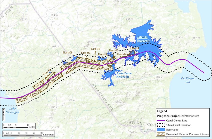
Figure 3.1-11: East Canal EMPAs
20Nicaragua Canal Project Description December 2014 / A
Figure 3.1-12: Lago de Nicaragua Dredge Disposal Areas
21Nicaragua Canal Project Description December 2014 / A
Table 3.1-5: Lago de Nicaragua Dredge Disposal Areas
Placement Area ID # Location Estimated Footprint Surface Storage Volume
(see Figure 3.1-12 for (Station) Existing Water Area (km2) (Million m3)
location) Depths (m)
LN-CDF1 40 5m 12 100
LN-CDF2 90 10 m 15 150
LN-OW1 30 – 125 Varies from 139 360
3 to 32 m
Total NA NA 166 610*
2 3
m = meter; km – square kilometer; m = cubic meter; NA = not applicable
Note: The remaining dredge spoil removed from Lago de Nicaragua will be placed in upland Excavated Material Placement Area
East-01.
The surficial fine sediments would be disposed of in two confined disposal facilities (CDFs) surrounded
by an engineered dike or seawall (i.e., LN-CDF1 and LN-CDF2) that would ultimately form islands in
Lago de Nicaragua, and on land at the eastern side of the lake. An in-water CDF is an engineered
structure consisting of dikes or other structures that extend above the water surface and enclose a disposal
area for containment of dredged material, isolating the dredged material from adjacent waters.
Figure 3.1-13 provides an example of a CDF.
22Nicaragua Canal Project Description December 2014 / A
Source: Uncredited Photo 2014
Figure 3.1-13: Example of a Confined Disposal Facility (CDF)
The dikes/seawalls are typically constructed with an inner core of rubble or even sand covered by
progressively larger stones with large armor rock (sourced from upland excavation areas) placed on the
outside face of the dike to protect against wave action (see Figure 3.1-14). The dike, which is at least
initially permeable, encircles the disposal area where the dredged material is placed. As dredged material
is pumped or placed in the CDF, the sediment particles settle out in the disposal area and excess water
either evaporates or percolates through the dike (USACE 1987).
23Nicaragua Canal Project Description December 2014 / A
Source: Image created by HKND
Figure 3.1-14: Typical Cross Section of a Confined Disposal Facility (CDF) Dike
These facilities would accept the fine surficial silts and clays dredged for the canal and would help
prevent that material from impacting turbidity and contaminant levels in Lago de Nicaragua. Water
quality monitoring at existing island facilities has confirmed that that CDFs are highly efficient at
retaining the sediment solids and any attached contaminants (Great Lakes Commission 2000).
The third dredged material disposal area is an open water disposal site (LN-OW1). This facility would
only accept coarser material like sands and excavated rock that underlie the fine surficial silts. This
material is heavy and would sink to the bottom of the lake with little potential to cause any turbidity
issues and typically has little or no contamination. HKND has indicated that the open water disposal site
would not be more than 3 meters in height above the lake bottom to avoid interfering with lake
navigation.
3.1.4.3 Marine Dredge Disposal Areas
HKND proposes three marine dredged material disposal areas, one in the Pacific and two in the
Caribbean (see Table 3.1-6).
24Nicaragua Canal Project Description December 2014 / A
Table 3.1-6: Marine Dredge Disposal Areas
Placement Area Storage Volume Surface Area Distance offshore Estimated Water
ID # (Million m3) (km2) (km) Depths
(m)
P-OW1 7 0.8 15 km >150 m
C-OW1 54 ~8.0 ~35 km >100 m
C-CDF1 182 14 0 – 2 km ~7 m
Total 143 ~22.8 NA NA
NA = not applicable
The Pacific disposal area (P-OW1) would accommodate the estimated 7 Mm3 of marine excavation
required to achieve the required depth for the Pacific approach channel.
The Caribbean disposal area (C-OW1) is intended to only accommodate the initial dredging of surficial
fine sediments from the Aguila Port site and from the lower Rio Punta Gorda. The exact location of this
disposal site has not yet been determined, but it will be required to meet the following siting criteria:
Minimum of 100 m depth of water;
Minimum of 15 kilometers offshore (likely to be at least 35 kilometers to achieve water depths of 100
meters);
Lack of nearby hard rock habitat; and
Located at a latitude south of Booby Cay to ensure marine currents do not carry turbidity to the
Booby Cay/Monkey Point/Bank 105 important habitat areas.
All other dredge material that is suitable (e.g., sand) would be used as fill to create the Aguila Port
reclamation area (i.e., C-CDF1). The Aguila Port has the capacity to accept a large volume of dredged
material, and would therefore serve as the primary disposal location for East Canal maintenance dredging
for the foreseeable future.
3.1.5 Breakwaters
The canal would include breakwaters at the Pacific, Caribbean, and Lago de Nicaragua canal entrances.
All breakwaters would follow the basic design as illustrated in Figure 3.1-15, with a 10 meters wide crest,
about 6.5 meters clearance amsl, and 1.5:1 slopes to the sea bed. The breakwaters would create an
effective canal width at the various entrances of approximately 500 meters.
25Nicaragua Canal Project Description December 2014 / A
Figure 3.1-15: Typical Cross Section of the Breakwater Structures
3.1.5.1 Pacific Breakwater
The Pacific breakwater would extend approximately 800 m from the shoreline on both sides of the canal.
It will be constructed with armor rock sourced from the Brito Lock excavation with tri-bar armor at the
ends (see Figure 3.1-16). The overall footprint of each breakwater will be about 62,000 square meters
(m2), or 124,000 m2 total for the two breakwaters.
26Nicaragua Canal Project Description December 2014 / A
Figure 3.1-16: Pacific Entrance Breakwater and Brito Port
3.1.5.2 Caribbean Breakwater
The Caribbean breakwater would include two different structures, one at each side of the canal. The
breakwater located to the north of the canal would extend south from Punta Aguila approximately 7
kilometers to a location about 3 kilometers southwest of Booby Cay. The breakwater located to the south
of the canal would be located about 1 kilometers north of the mouth of the Rio Punta Gorda and would be
oriented perpendicular to the shoreline and extend approximately 3.5 kilometers (see Figure 3.1-17). The
overall footprint of north breakwater would be about 238,000 m2. The overall footprint of the south
breakwater will be about 105,000 m2. Combined, this would be approximately 343,000 m2 total for the
two breakwaters.
27Nicaragua Canal Project Description December 2014 / A
Figure 3.1-17: Caribbean Entrance Breakwaters and Aguila Port
The breakwaters at the two Lago de Nicaragua entrances would be smaller and intended to control
sediment deposition, and help stabilize the lake shoreline at the canal entrances. Two breakwaters would
occur on either side of the canal at both canal entrances and would extend approximately 200 meters from
shore. The overall footprint of each breakwater would be about 9,000 m2, or 18,000 m2 total for the two
breakwaters.
3.2 PORTS
Canal construction would require the import of approximately 21M tons of materials and supplies, most
of which are anticipated to be transported by ship to the Corinto and Bluefields ports. HKND proposes to
use these existing ports to transfer these materials and supplies to shallow draft barges that would be used
to transfer these materials to two proposed Project ports, one on the Pacific called the Brito Port
(approximately 4 km2 in area) and one on the Caribbean called the Aguila Port (14 km2 in area). The ports
would provide logistical support during the construction of the canal and would afterwards serve as
international ports. These ports would support growth of the Nicaraguan economy by providing improved
transport connections for agricultural and other Nicaraguan producers with major Atlantic market
destinations. These ports would serve as trans-shipment ports for container handling and normal cargo
loading.
28Nicaragua Canal Project Description December 2014 / A
3.2.1 Brito Port
The Brito Port (see Figure 3.1-16) would have a design capacity of 1.68 million TEU/year and would
include the following facilities:
North Wharf structure, approximately 1,100 meters long, capable of supporting a 200,000 dry weight
tonnage (DWT) bulk carrier or 25,000 TEU container ship;
West Wharf berthing facilities, approximately 1,200 meters long, accommodating:
o Three 70,000 DWT container berths;
o One 30,000 DWT oil/fuel jetty;
o 13 workboat berths; and
Other miscellaneous supporting facilities.
3.2.2 Aguila Port
The Aguila Port (see Figure 3.1-17) would have a design capacity of 2.5 million TEU/year and would
include the following facilities:
Wharf structure design capable of supporting a 200,000 DWT container ship;
Berthing facilities, approximately 1,300 meters long, accommodating:
o Three 150,000 DWT container berths;
o One 30,000 DWT oil/fuel jetty;
o Eight workboat berths; and
Other miscellaneous supporting facilities.
3.3 ASSOCIATED PROJECT FACILITIES
3.3.1 Vehicular Transportation Improvements
3.3.1.1 Pan-American Highway Bridge
HKND proposes to build one bridge as part of this Project for the Pan-American Highway. A ferry is
proposed where the canal would cross Nicaragua Route 25 (Acoyapa-San Carlos Road). The canal would
not cross any other major roads that would warrant construction of a bridge or provision of a ferry.
The Pan-American Highway Bridge would use a span arrangement and provide 80 meters clearance over
the average canal water level (approximate elevation of 31.3 meters), and an overall length of 4,930
meters. Structural arrangement is shown below in Figure 3.3-1.
29Nicaragua Canal Project Description December 2014 / A
Figure 3.3-1: Proposed Pan American Highway Cable-Stayed Bridge Profile
3.3.1.2 Ferry
HKND proposes a vehicular ferry in lieu of a bridge where the canal crosses the Acoyapa-San Carlos
road (Nicaragua Route 25). Ferry terminals would be constructed on both sides of the canal, and a ferry
would operate on an approximately hourly basis at no cost to users until a reasonable substitute is
available.
3.3.1.3 Permanent Public Roads
Road access to most of the western section of canal is available through the existing road network,
although improvements would be required. Similarly, road access to both sides of Lago de Nicaragua is
also available. However, access by road to the eastern section of the canal is currently available only at its
western end near San Miguelito.
To provide reliable public access to critical Project facilities, HKND proposes to improve or construct
three roads:
Pan-American Highway to Brito Port Road; and
Nueva Guinea to Aguila Port Road.
Table 3.3-1 presents the basic design parameters for these roads. Figure 3.3-2 presents a typical cross
section for these roads.
Table 3.3-1: Basic Road Design Parameters
Road Section Road Type Length Width Surface Material
Brito Port to Pan-American Public 23 km 12 m Asphalt
Highway
Aguila Port to Nueva Public 103 km 12 m Asphalt
Guinea
30Nicaragua Canal Project Description December 2014 / A
Figure 3.3-2: Cross-section of Public Roads
In addition, HKND proposes to construct permanent paved roads to provide access to the reclaimed
EMPAs. The exact location of these roads has not yet been determined, but they would generally be
located within a 100-meter-wide corridor alongside the top of the batter slope.
3.3.1.4 Permanent Private Maintenance Roads
In addition to the facility access roads, HKND intends to build 5-meter wide gravel maintenance roads on
both sides of the canal along most of the route, except on the East Canal between the Camilo Lock and
the Caribbean Sea on the north side of the canal and between the Agua Zarca Reservoir and the Caribbean
Sea on the south side for biodiversity conservation. Vehicular access to these private maintenance roads
would be limited to canal-related traffic. Figure 3.3-3 presents a typical cross section for these roads.
31Nicaragua Canal Project Description December 2014 / A
Figure 3.3-3: Cross-section of Maintenance Road
3.3.1.5 Camilo Lock Maintenance and Access Road
HKND would construct an approximately 8-kilometer-long asphalt spur road to connect the Nueva
Guinea to Aguila Port Road to the Camilo Lock. This would be a private access road. Vehicular access
would also be included in the design of the Camilo Lock so as to provide maintenance access across the
Camilo Lock to the Atlanta Dam. Limited public access across the lock would be allowed, but only for
local residents with appropriate identification.
3.3.2 Power Generation and Transmission Lines
During construction, the Project might connect to the Nicaraguan electricity grid for power, but would
primarily rely on diesel generators to provide required power. During operation, the Project would obtain
power from the Agua Zarca Hydropower Project supplemented and possibly with securing power from
the Nicaragua electrical grid.
3.3.2.1 Agua Zarca Hydropower Facility
The Agua Zarca Hydropower Facility would be located on the south side of the canal at approximately
Station 205 kilometers. It would consist of an approximately 65-meter high dam, creating a reservoir on
the Agua Zarca River with a surface area of approximately 48.5 km2 and a storage volume of
approximately 1,100 gigaliters. The facility is predicted to generate over 10 megawatts (MW) of power,
assuming an average annual flow of 24 cubic meters per second and a gross head of approximately
55 meters. An approximately 22-kilometer-long transmission line will connect the Agua Zarca
powerhouse to the Camilo Lock substation, which would cross and then run along the north side of the
32Nicaragua Canal Project Description December 2014 / A
canal. The Agua Zarca Hydropower Project would be operating by the time canal operations commence
and will provide power for the operation of the Camilo Lock.
3.3.2.2 Connection to the Nicaragua Electrical Grid
Subject to reliability and availability analysis, both the Camilo and the Brito locks would be connected to
the Nicaragua electrical grid for power during operations. This would require constructing new electrical
transmission lines totaling 125 kilometers and a new 69 kilovolt (kV) electrical substation near each lock
as presented in Table 3.3-2 and Figure 3.3-4. Both locks would also have diesel generators for emergency
power.
Figure 3.3-4: Proposed Electrical Transmission Towers
33Nicaragua Canal Project Description December 2014 / A
Table 3.3-2 provides characteristics of the two transmission lines and substations that would be needed to
supply power from the national grid during construction.
Table 3.3-2: Transmission Lines
Voltage Number of Total Length
Starting Line End of Line
Rating Loops (km)
RIVAS Substation 138kV Brito Substation 69kV Double circuit 11
COROCITO Substation 69kV Camilo Substation 69kV Double circuit 114
kV = kilovolt; km = kilometer
3.3.3 Concrete Batch Plants
Approximately 10 Mm3 of concrete would be needed primarily to construct to the two locks, but would
also be used for the breakwaters, building, and other miscellaneous facility construction. The batch plant
combines sand/aggregate with cement to make concrete. HKND would import cement and source
aggregate locally (see Section 3.3.4, Aggregate Quarries). The exact location for these plants has not yet
been determined, but one plant would be located near each lock or its quarry.
3.3.4 Aggregate Quarries
The concrete would be made by combining cement with aggregate (sand and crushed stone). The cement
would likely be imported. The aggregate would be sourced from the following two locations (see Table
3.3-3): one near the Brito Lock (Rio Grande quarry) and one near the Camilo Lock (Camilo quarry).
Table 3.3-3: Aggregate Quarries
Aggregate Location Estimated Volume of Aggregate Used for
Quarry Surface Area Needed/Available
Rio Grande 1 km from Brito 2.2 km2 9.2 Mm3 / 158 Mm3 Brito Lock and
quarry Lock Pacific breakwater
Camilo quarry 5 km northeast of 1.1 km2 9.9 Mm3 / 35.1 Mm3 Camilo Lock and
Camilo Lock Caribbean breakwater
km2 = square kilometers; Mm3 = million cubic meters
3.3.5 Borrow Areas
Three borrow areas are proposed to source material for dam core walls (see Table 3.3-4).
Table 3.3-4: Borrow Areas
Borrow Area Location Average Thickness Area Available Volume
#1 2,200 m west of the 2.0 m 15.1 km2 30 Mm3
dam
#2 600 m southwest of 2.5 m 1.4 km2 3.5 Mm3
the dam
#3 3,700 m southwest 2.5 m 3.1 km2 7.7 M m3
of the dam
M = meter; km2 = square kilometers; Mm3 = million cubic meters
34You can also read