Novel approach to improve shale stability using super-amphiphobic nanoscale materials in water-based drilling fluids and its field application
←
→
Page content transcription
If your browser does not render page correctly, please read the page content below
Reviews on Advanced Materials Science 2022; 61: 41–54
Research Article
Xuwu Luo, Guancheng Jiang*, Guoshuai Wang, Lili Yang, Yinbo He, Kaixiao Cui, and Jun Yang
Novel approach to improve shale stability using
super-amphiphobic nanoscale materials in
water-based drilling fluids and its field
application
https://doi.org/10.1515/rams-2022-0003 addition of 1% SA-NPs in WBDFs could reduce the linear
received September 03, 2021; accepted October 18, 2021 swelling rate from 40.5 to 6.0%, increase the shale cuttings
Abstract: In this study, super-amphiphobic nano-silica recovery percentages from 82.5 to 95.6%, increase the plug-
nanoparticles (SA-NPs) were used to enhance the shale ging rate of low permeability shale core from 81.25 to
stabilization performance of water-based drilling fluids 94.00%, and raise the high-temperature and high-pressure
(WBDFs) by altering the surface wettability, preventing uniaxial compressive strength from 3.45 to 4.87 MPa.
the capillary self-priming effect, and plugging the nano- Compared with the polyether amine and fumed nano-silica,
micro pores of shale. The results of transmission electron the addition of SA-NPs produced the best performance.
microscopy, particle size distribution, and scanning elec- Based on the excellent shale stabilization performance of
tron microscopy characterization revealed that SA-NPs SA-NPs, a high-performance WBDF was developed and
exhibited a nanoscale “coalesce” structure, which is com- applied in Dagang Oilfield. During the drilling operation,
posed of spherical particles joined together, and could form no wellbore instability, sticking, and other complex situa-
a nano-papillary structure on the shale surface. Due to the tions occurred. The results indicate that SA-NPs could better
presence of nano-micro scale rough structures and ultra- address the issue of wellbore instability in shale formations
low surface energy components, the shale treated by SA- and have a great application prospect in shale well drilling.
NPS exhibited super-amphiphobic surface property in the Keywords: super-amphiphobic surface, capillary force,
contact angle test. Contact angles of water and hexadecane shale formation, water-based drilling fluids, inhibition
on the shale surface reached up to 154.13° and 151.34° after performance
being treated with SA-NPs, respectively. Furthermore, the
1 Introduction
* Corresponding author: Guancheng Jiang, State Key Laboratory of
The rapid growth of global oil and gas demand and the
Petroleum Resources and Prospecting, China University of
Petroleum (Beijing), Beijing 102249, People’s Republic of China;
depletion of conventional oil and gas resources have driven
Ministry of Education (MOE) Key Laboratory of Petroleum the rapid exploration and exploitation of unconventional oil
Engineering, China University of Petroleum (Beijing), Beijing and gas resources, especially shale oil and gas resources [1].
102249, People’s Republic of China, Characterized by rich clay mineral contents, developed
e-mail: m15600263100_1@163.com bedding structures, and abundant nano-micro cracks and
Xuwu Luo: State Key Laboratory of Petroleum Resources and
nanopores, shale has a strong amphiphilicity and capillary
Prospecting, China University of Petroleum (Beijing), Beijing
102249, People’s Republic of China; Western Drilling Engineering self-imbibition effect [2–4]. It spontaneously absorbs free
Company of PetroChina, Karamay 834099, water from drilling fluid under capillary forces. The result-
People’s Republic of China ing hydration swelling and dispersion of clay minerals thus
Guoshuai Wang, Lili Yang, Yinbo He, Kaixiao Cui, Jun Yang: State widen cracks and reduce shale strength [5–7]. Therefore,
Key Laboratory of Petroleum Resources and Prospecting, China
in the drilling process of shale formation using water
University of Petroleum (Beijing), Beijing 102249, People’s Republic
of China; Ministry of Education (MOE) Key Laboratory of Petroleum
based-drilling fluids (WBDFs), wellbore instability, such
Engineering, China University of Petroleum (Beijing), Beijing as borehole shrinkage, spalling, and even collapse often
102249, People’s Republic of China occurs, greatly increases the drilling cost and even
Open Access. © 2022 Xuwu Luo et al., published by De Gruyter. This work is licensed under the Creative Commons Attribution 4.0
International License.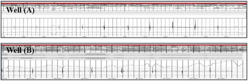
42 Xuwu Luo et al.
severely restricts the exploration and development process the capillary self-priming effect. Therefore, these conven-
of shale oil and gas resources [8,9]. tional nanomaterials cannot effectively inhibit the surface
To address the wellbore instability issue in shale for- hydration of the shale and prevent the intrusion of free water
mations, even though WBDFs with better inhibition prop- to the greatest extent. In comparison, super-amphiphobic
erty were developed, such as potassium chloride/partially nanomaterials have recently attracted significant attention
hydrolyzed polyacrylamide (KCl/PHPA) drilling fluids, satu- due to their unique characteristics, which can simulta-
rated brine drilling fluids, silicate-based drilling fluids, poly- neously endow the solid surface with the characteristics of
amine drilling fluids, and KCl/diamino hexane drilling fluids repelling water, oil, and organic liquid [31]. Moreover, it
[10–15], they cannot maintain the wellbore stability well in performs the functions of self-cleaning, self-healing, anti-
shale formations. Therefore, invert emulsion drilling fluids corrosion, anti-pollution, and super-protection, consequently
(IEDFs), a type of water-in-oil emulsion drilling fluids, were showing a wide application prospect in daily life, environ-
used to drill shale formations [16]. Though excellent in well- mental protection, industrial production, medical treatment,
bore stability and drilling efficiency in shale formations military, and other aspects [32–36]. Fluorinated NPs are com-
owing to the absence of contact between the wellbore rock monly used to construct super-amphiphilic surfaces [37–39].
and water phase [17], IEDFs show nonetheless inherent dis- Lu et al. directly mixed two kinds of TiO2 of different particle
advantages, including difficulty in mud cakes clearing and sizes (60–200 and 21 nm) with 1H,1H,2H,2H-perfluoro-
cuttings handling, high post-treatment costs, and severe octyltriethoxysilane to obtain an ethanol suspension of
environmental pollution. To date, the use of IEDFs in many 1H,1H,2H,2H-perfluorooctyltriethoxysilane-coated TiO2 nano-
oilfields has been restricted by strict environmental protection particles, such that when applied to different substrate sur-
laws and high costs [18–20]. Therefore, developing high-per- faces such as glass, steel, cotton fabrics, and paper, it shows
formance WBDFs to replace IEDFs against the above issues super-amphiphobic [40]. Our group has previously synthe-
has become a research focus in the petroleum industry. sized a nanofluid from nano-silica, MCNTs, and trichloro
Studies have gradually pointed out that reducing (1H,1H,2H,2H-perfluorooctyl) silane, which can change
capillary force and increasing rock hydrophobicity are ben- the wettability of sandstone core surface from amphi-
eficial to the wellbore stability of shale formations [21–23]. philic to amphiphobic [41].
Shi et al. reported that compound surfactants (nonionic In this study, a novel super-amphiphobic nanoscale
surfactant and fluorocarbon surfactant) in WBDFs could material (SA-NPs), nano-silica grafted with amine groups
enhance the hydrophobicity of wellbore rocks and reduce and halothane segments, was employed to improve the
the contact between free water in WBDFs and wellbore rock, wellbore stabilization performance of WBDFs in shale
thus improving wellbore stability [24]. Xu et al. synthesized well drilling operations. The presence of amine groups
a hydrophobic-modified polymer-based silica nanocompos- contributes to the absorption on the shale surface. The
ite. It can make the shale surface more hydrophobic, nanoscale structure and halothane segments can improve
thereby showing excellent shale inhibition performance nano-micro scale shale surface roughness, construct super-
[25]. Yue et al. optimized a surfactant combination (cetyl amphiphobic surface, and plug nano-micro pores. A flow-
trimethyl ammonium bromide and sodium dodecylbenzene chart of the procedure of this research is shown in Figure 1.
sulfonate) that can improve wellbore stability in shale First, the microstructure of SA-NPs was characterized
formation by effectively reducing the surface tension of through transmission electron microscopy (TEM) and par-
WBDFs or freshwater and increasing the contact angle ticle size distribution measurement, and its influence on the
with shale [26]. Nevertheless, being unable to form com- shale surface microstructure was studied by scanning elec-
plete hydrophobic surfaces, much less super-hydrophobic tron microscopy (SEM). Then, the wetting and interface
ones, these surfactants or hydrophobic polymers can only characteristics of SA-NPs on the shale surface and glass
increase the hydrophobic degree of rocks, and thus cannot capillary were investigated by the contact angle test and
effectively prevent water intrusion. Recently, nanomater- capillary force measurement. The shale stabilization perfor-
ials such as fumed silica (SiO2) nanoparticles (NPs), tita- mance of SA-NPs in WBDFs was further evaluated through
nium dioxide (TiO2) NPs, graphene oxide, and multi-walled the linear swelling test, hot-rolling recovery test, plugging
carbon nanotubes (MCNTs) have also shown great potential rate test, and HTHP uniaxial compressive strength test.
in improving the wellbore stability of shale formations Meanwhile, the performance of SA-NPs was compared
[27–30]. Because they can plug the nano-micro pores on the with that of polyether amine (PA) and fumed nano-silica
shale surface, they can avoid free water intrusion. However, to fully demonstrate the advantage of SA-NPs. Finally, with
these conventional nanomaterials are hydrophilic. They SA-NPs as the core treatment agent, a high-performance
cannot change the wettability of the rock surface and prevent WBDF was prepared, evaluated, and applied on the oilfield.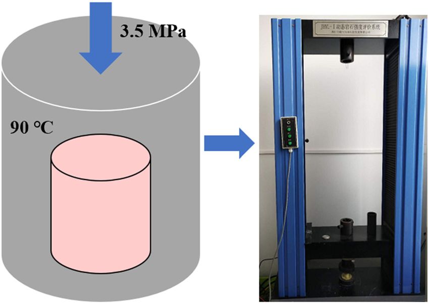
Novel approach to improve shale stability using SA-NPs 43
Figure 1: Flowchart of the procedure of this research.
2 Materials and methods Malvern Zetasizer Nano ZS instrument (Malvern, England).
In these tests, the concentration of the sample in ethyl
alcohol was 0.1% w/v.
2.1 Materials
The influence of SA-NPs on the surface micro-mor-
phology of shale was examined by a SU8010 scanning
The super-amphiphobic nano-silica nanoparticles (SA-NPs),
electron microscope (SEM; Tokyo, Japan). Specifically,
a commercial product provided by Shida Bocheng Technology
in preparation of a dispersion, 0.3 g SA-NP powder was
Co., Ltd (Beijing, China), were synthesized by fluorination
modification of fumed SiO2 NPs. The chemical structure of
the SA-NPs is shown in Figure 2. Poly dimethyldiallyl ammo- F F
F F F
nium chloride (PDMDAAC), PA D-2000, SiO2 with a diameter F
F F F F
of 20 nm, KCl, sodium chloride (NaCl), and calcium chloride F F
F
F
(CaCl2) were purchased from Energy Chemical (Shanghai, F F F
F F
F F F
China). In addition, Ethyl alcohol and hexadecane were pur- F F
F
chased from Aladdin Chemical Inc. (Shanghai, China). The F
glass capillary tube with a radius of 0.15 mm was provided Si Si
O O
by Changzhou Kejing Glass Co., Ltd (Changzhou, China). OO OO
Bentonite (consisting of 69.3% montmorillonite), shale
F F F F F O
cuttings, and a WBDF (ρ = 1.4 g·cm−3) were supplied by F
Si O
O
F O Si NH2
China National Petroleum Corporation (CNPC) Western O O
F F F F F F
Drilling Engineering Co., Ltd (Karamay, China). The mineral OO
O OO
compositions of the shale cuttings and formulation of WBDFs Si O
Si
are shown in Tables 1 and 2, respectively.
F
F
H2N F F
F F
2.2 Characterization of SA-NPs F F
F F
The TEM images of SA-NPs were obtained by a JEM-2100 F F
F
transmission electron microscope (Tokyo, Japan). The
particle size distribution of SA-NPs was measured by a Figure 2: The chemical structure of the SA-SiO2.44 Xuwu Luo et al.
Table 1: Mineral composition of the shale cuttings
Component Quartz Potassium feldspar Plagioclase Calcite Dolomite Augite Clay mineral
Content (%) 31.7 1.4 2.1 17.4 2.8 2.0 42.6
Table 2: Formulation of WBDFs wellbore stability. In this work, the nano-micro pores of
shale are simulated by glass capillary tubes whose capil-
Additives Composition (g) lary forces were treated with different liquids and tested
Fresh water 300 by the method shown in Figure 3. In this method, the
Bentonite 3 glass capillary tubes were immersed in different test
NaOH 0.9 liquids for 1 h and dried in an oven at 80°C for 4 h.
Filtrate reducer XZ-KGJ 6 Then, the well-prepared glass capillaries were inserted
Plugging agent XZ-FDJ 9
vertically into DI water of the same height. The capillary
Plugging agent OSD-1 6
Lubricant JHRH-1 6
force can be calculated using equation (1) [43].
Potassium polyacrylamide KPAM 0.6 2σ cos θ
KCl 24 pc = , (1)
r
NaCl 60
where pc is the capillary force (Pa) measured at 25°C; σ is
the surface tension (73.2 mN·m−1) of DI water; θ is the
dispersed in 10 mL of ethyl alcohol under ultrasonic
contact angle (°) of capillary inner surface; and r is the
treatment. The shale sample was subsequently immersed
capillary radius (0.15 mm).
in the dispersion for 24 h and dried afterward in a vacuum
oven at 70°C for 2 h for SEM testing.
2.4 Shale stabilization performance
2.3 Wetting and interface characteristics evaluation
2.3.1 Contact angle test 2.4.1 Linear swelling test
Generally, the solid surface is considered to be super- The linear swelling test was carried out to investigate the
amphiphobic when it has contact angles with oil and ability of WBDFs to inhibit the hydration swelling of
water phases, both greater than 150° [42,43]. The contact shale. First, shale cuttings powder (5 g) was pressed
angle was measured using the following procedure. The
shale samples were first immersed in SA-NPs dispersion,
SiO2 dispersion, and commonly used shale inhibitors
aqueous solutions separately for 24 h, and then dried in
a blast drying oven at 80°C for 4 h. Then, hexadecane capillary tube r
with a surface energy of 73.2 mN·m−1 and deionized (DI)
water with a surface energy of 27.2 mN·m−1 were used as
test liquids, respectively. The contact angle of the shale θ
surface was at last determined by a JC2000D3 contact
angle measuring instrument (Shanghai, China), in which
the droplets volume of test liquid was set to 5 µL.
2.3.2 Capillary force measurement
water
The existence of lots of micro-nano pores in the shale
surface brings natural capillary force that allows shale
to spontaneously absorb water, which thereby affects Figure 3: The schematic diagram of capillary force measurements.Novel approach to improve shale stability using SA-NPs 45
into a cylindrical pellet under a pressure of 10 MPa for 2.4.4 HTHP uniaxial compressive strength test
5 min. Then, the pellet was installed in the CPZ-2 dual-
channel linear swell meter (Qingdao, China), with 20 mL The nature of wellbore instability is mechanical instability.
of drilling fluid filtrate added to immerse the shale cut- Therefore, the influence of different mud samples on the
tings pellet. Finally, the swelling height was recorded artificial shale cores’ strength was evaluated by the uni-
every 30 s for 24 h. Accordingly, the linear swelling rate axial compressive strength experiment. During the experi-
is calculated using equation (2) [23]. ment, bentonite (20 g) was pressed into a columnar core
under 15 MPa pressure for 15 min. Then, the bentonite core
ht − h0
Linear swelling rate = × 100%, (2) was placed in a stainless steel sealed kettle containing
h0
mud samples and immersed at a fixed pressure difference
where ht is the final height (mm) of shale cuttings pellet of 3.5 MPa and 90°C for 7 days (Figure 4). Uniaxial com-
after immersed in test liquid for a certain time t; and h0 is pressive strength measurement was conducted using a
the initial height (mm) of shale cuttings pellet. JHYL-1 dynamic core strength evaluation instrument
(Jingzhou, China).
2.4.2 Hot-rolling recovery test
2.5 Rheological and fluid loss properties
The hot-rolling recovery test was conducted to investigate evaluation
the ability of WBDFs to inhibit the hydration disintegration
of shale cuttings at borehole temperature. First, 20 g shale The rheological properties of WBDFs were investigated by
cuttings (6–10 mesh) and 300 mL of drilling fluids were a ZNN-D6 six-speed rotational viscometer (Qingdao, China)
added to a sealed stainless steel aging jar and rolled at whose readings at 300 and 600 rpm were recorded and
140°C in a GW300-X roller oven (Qingdao, China) for 16 h. marked as θ300 and θ600, respectively. The rheological para-
After cooling, the remaining shale cuttings were screened meters were calculated by the following equations:
by a 40-mesh sieve, washed with clean water, and dried in a
AV = 0.5θ600, (5)
hot oven at 75°C for 24 h. The recovery percentage of shale
cuttings is calculated according to equation (3). PV = θ600 − θ300, (6)
m1 YP = 0.5(θ 300 − PV), (7)
Recovery percentage = × 100%, (3)
m0
where AV is the apparent viscosity (mPa·s), PV is the
where m1 is the remaining mass and m0 is the original plastic viscosity (mPa·s), and YP is the yield point (Pa).
mass of the shale cuttings. The medium pressure filtration volume (FLAPI) and
HTHP filtration volume (FLHTHP) were measured according
to the method recommended by American Petroleum
2.4.3 Plugging rate test
The plugging rate test was conducted to investigate the
ability of WBDFs to plug the nano-micro pores and frac-
tures of the shale. First, the positive permeability (Ki) of
the original shale cores with kerosene being the fluid in the
first place was examined using a JHMD-2 core dynamic
damage evaluation instrument (Jingzhou, China). Then,
the core was positively contaminated with different dril-
ling fluids for 120 min under a pressure difference of 6 MPa
and a confining pressure of 2 MPa. At last, the positive
direction permeability (Kp) of the core was examined by
using brine (4% NaCl) as the fluid, and the plugging rate
(Pr) value is calculated using equation (4).
Ki − Kp Figure 4: The schematic diagram of HTHP uniaxial compressive
Pr = × 100%. (4)
Ki strength tests.46 Xuwu Luo et al.
Institute (API). FLAPI was measured by an SD-6 medium- surface [44,45]. As shown in Figure 5, the microstructure
pressure filtration apparatus (Qingdao, China) at a fixed and size of SA-NPs were demonstrated by the TEM and
pressure difference of 0.69 MPa and room temperature, in particle size distribution curve. In the TEM images of
which the FLAPI was recorded after 30 min since the begin- Figure 5a and b, SA-NPs exhibit a nanoscale “coalesce”
ning. FLHTHP was measured by a GGS42-2A HTHP filtration structure composed of joint spherical particles, which is
apparatus (Qingdao, China) at a fixed pressure difference attributed to the association of hydrogen bonds between
of 3.5 MPa and a temperature of 140°C. the amine groups grafted on the surface of SA-NPs. In
Figure 5c, the particle size of SA-NPs distributes in the
range from 70 to 200 nm with an average particle size of
about 105.3 nm, meaning that SA-NPs are able to enter
3 Results and discussion and plug shale nano-micro pores and cracks. On the
other hand, the surface of the original shale presents a
3.1 Characterization of SA-NPs relatively smooth nano-micro scale structure, as shown
in Figure 5d. After treatment with SA-NPs dispersion, lots
The construction of a nano-micro scale rough structure is of spherical particles are adsorbed and distributed on the
one of the key elements to form a super-amphiphobic surface of the treated shale in the form of uneven
(a) (b)
40 (c)
30
Intensities (%)
20
10
0
100 1000
Particle size (nm)
(d) (ee)
1 μm 1 μm
Figure 5: The microstructure and size of SA-NPs. TEM images of SA-NPs (a) and (b); particle size distribution of SA-NPs (c); SEM image of
original shale surface (d); and SEM image of shale treated with SA-NPs (e).Novel approach to improve shale stability using SA-NPs 47
aggregates, forming a nano-papillary structure (Figure 5e). super-amphiphobic surface if the shale is immersed in
This new structure, to a great extent, improves the SA-NPs suspension for a period, which is suitable for the
roughness of the shale surface at the nano-micro scale. actual drilling situation. The super-amphiphobic property
Simultaneously, SA-NPs used in our study have been enables the shale surface to perform self-cleaning and
pre-grafted with halothane segment and can present anti-polluting activities, which effectively prevents contact
super-low surface energy components. Therefore, the with water and organic liquid molecules, and thereby,
shale treated by SA-NPs would achieve super-amphi- inhibits hydration swelling and mineral particle cohesion.
phobic surface property. In addition, the contact angles between the water
phase and shale surface after treated with several com-
monly used shale inhibitors were also measured (Figure 7).
3.2 Contact angle test Wherein, KCl (10.32°) and PDMDAAC (11.41°) can be observed
to slightly reduce the contact angle with the water phase, which
Figure 6 shows water and oil phase contact angles on the can be related to the increase in hydrophilicity of the shale
shale surface before and after being treated with SA-NPs. brought by the cation groups absorbed on the shale surface.
In this test, DI water and hexadecane were used as water On the contrary, PA (27.34°) and SiO2 (31.72°) slightly increase
and oil contact phases, respectively. Before the treatment, contact angle, even then it is always less than 32°. It is evident
the contact angles of DI water and hexadecane on the that commonly used inhibitors cannot alter the wettability of
original shale surface were only 14.65° and 5.09°, respec- shale, and it remains similar to the hydrophilic property. In
tively, as shown in Figure 6a and b, indicating an amphi- contrast, SA-NPs (154.13°) generate a super-hydrophobic surface
philic property. Whereas, as shown in Figure 6c and d, on shale playing a rather different role. The inability of these
after tiny amounts of SA-NPs treatment, the two contact common inhibitors to avoid capillary self-priming effect and
angles drastically raised to 154.13° and 151.34°, respec- shale’s surface hydration results from the failure of avoiding
tively. This change in the surface wettability marked the the association of water molecules with the shale surface and
forming of super-amphiphobic property. This experiment pores will be further verified in the following capillary force
illustrates that the amphiphilic surface would become a measurement experiment.
(a) (b)
14.65° 5.09
(c) (d)
154.13° 15 .34°
Figure 6: DI water and hexadecane contact angles on shale surface before and after being treated with SA-NPs. Water droplet on original
shale surface (a); hexadecane droplet on original shale surface (b); water droplet on shale surface treated with SA-NPs (c); and hexadecane
droplet on shale surface treated with SA-NPs (d).48 Xuwu Luo et al.
force, the effect of mitigating water intruding is minimal yet
160
beneficial. Nevertheless, the negative capillary force exhibited
140 by SA-NPs illustrates its ability to alter and turn the capillary
attraction force into the capillary repelling force that avoids
Water contact angle (°)
120
capillary self-priming and water-blocking phenomenon. The
100 contact angle test and capillary force test verified the ability of
SA-NPs to reverse the wettability of the shale surface and
80
avoid capillary self-priming. Theoretically, this ability will
60 greatly improve the stability of the shale. Then, we further
evaluated the ability of SA-NPs to stabilize shale in WBDFs.
40
20
0
Blank PDMDAAC PA KCl SiO2 SA-SiO2
3.4 Shale stabilization performance of SA-
NPs in WBDFs
Figure 7: The water phase contact angle of the shale treated with SA-
NPs and commonly used inhibitors solution at a concentration of 3.4.1 Linear swelling test and hot-rolling recovery test
3 wt%.
The inhibition performance of four samples, including
3.3 Capillary force measurements fresh tap water, WBDFs, WBDFs added with 2% PA
(PA-WBDFs), and WBDFs added with 1% SA-NPs (SA-
Capillary force measurement was conducted to evaluate WBDFs), were tested for comparison and the corresponding
the ability of SA-NPs and commonly used inhibitors to experimental results are shown in Figures 9 and 10. After
avoid capillary self-priming. Typically, a greater capillary immersed in water and WBDFs for 24 h, the shale cuttings
force means a stronger self-priming ability, while a negative pellet has linear swelling rates reaching as high as 96 and
capillary force indicates a conversion from the capillary attrac- 40.5%, respectively. These rates marked a severe swelling of
tion force into the capillary repulsion force. Figure 8 shows shale cuttings in these two solutions especially in water that
the capillary forces of the glass capillary tube treated with harms borehole stability. As an effective shale inhibitor, PA
SA-NPs and commonly used inhibitors solutions, with can reduce the swelling degree to 13.5%. Nonetheless, this
results ordering as follows: SA-NPs (−833.78 kPa) < SiO2 performance is still far from satisfactory, especially for good
(789.62 kPa) < PA (799.13 kPa) < KCl (817.43 kPa) < PDMDAAC horizontal drillings. Therefore, the inhibiting performance
(817.44 kPa) < Blank (880.73 kPa). While the result indicates a of common shale inhibitors is not sufficient to impede
conventional inhibitors’ ability to slightly reduce the capillary
Water
100
WBDFs
1000 PA-WBDFs
Linear swelling rate (%)
800 SA-WBDFs
80
600
Capillary force (KPa)
400 60
200
0 40
Blank PDMDAAC PA KCl SiO2 SA-SiO2
-200
20
-400
-600
0
-800 0 200 400 600 800 1000 1200 1400 1600
-1000 Time (min)
Figure 8: Capillary forces of the glass capillary tube treated with SA- Figure 9: The linear swelling rate of shale cuttings powder in dif-
NPs and commonly used inhibitors. ferent WBDFs.Novel approach to improve shale stability using SA-NPs 49
The primary recovery percentage observed to increase the plugging rates of WBDFs from
100 The secondary recovery percentage 81.25 to 84.61% and then 94.00%, respectively. Com-
Shale recovery percentage (wt%)
pared to SiO2, WBDFs with 1% SA-NPs demonstrated a
better stabilizing ability as SA-NPs not only physically
80
plug the shale pores, but also change the wettability of
shale pore throats, thereby increasing the resistance of
60 the liquid phase through pore throats.
40
3.4.3 HTHP uniaxial compressive strength test
20
The HTHP uniaxial compressive strength of bentonite
cores immersed in different WBDFs is shown in Figure 11.
0
Water WBDFs PA-WBDFs SA-WBDFs Compared with the original bentonite core, the core
strength decreases sharply from 8.89 to 1.82 MPa after
Figure 10: Recovery percentages of shale cuttings in different immersion in clear water, indicating a great reduction in
WBDFs.
core strength in a water environment. Even though the
reduction level in uniaxial compressive strength is rela-
borehole instability problems such as wellbore shrinkage.
tively improved after replacing water with WBDFs, the
On the contrary, When SA-NPs were added instead, the
result is far from satisfactory, especially when it comes
linear swelling rate of SA-WBDFs was further reduced to
to horizontal shale-well drilling. With the addition of PA,
6%, indicating the superior inhibition performance of SA-
SiO2, and SA-NPs, the uniaxial compressive strength of
NPs than that of PA inhibitor. After adding 1% SA-NPs to
bentonite cores was stronger than that in the original dril-
WBDFs, the primary recovery percentage and secondary
ling fluid, which increased to 4.12, 3.26, and 4.87 MPa,
recovery percentage increased from 82.5% and 24.7% to
respectively. Therefore, it can be concluded that the addi-
95.6% and 79%, respectively, implying an effective absorp-
tion of SA-NPs resulted in the highest uniaxial compres-
tion made by SA-SiO2-NPs on shale surface to prevent shale
sive strength. The reason behind this phenomenon is that
hydration dispersion without degrading or falling due to
while PA can only inhibit bentonite hydration swelling
high temperature and long duration. It is also worth noting
and SiO2 can only physically plug core, SA-NPs not only
that the shale recovery percentage of SA-WBDFs is the
simultaneously achieve these effects, but also reverse the
highest and better than that of PA-WBDFs, once again
showing the excellent inhibition performance of SA-NPs.
10
HTHP uniaxial compressive strength (MPa)
3.4.2 Plugging rate test
8
The addition of nano-materials to WBDFs may potentially
plug shale nano-micro pores and cracks and reduce the
penetration of drilling fluid filtrate into the borehole rock, 6
thereby reducing borehole instability [19]. The plugging
rates of WBDFs, WBDFs with 1% SiO2 (SiO2-WBDFs), and
4
SA-WBDFs for low permeability shale core are shown in
Table 3. The addition of SiO2 and SA-NPs could be easily
2
Table 3: The plugging rate (Pr) of different WBDFs
0
nk t er s s s Fs
Mud system (Ki)/D (Kp)/D (Pr)/% Bl a Wa DF DF DF BD
WB - WB -W
B
-W
PA A
Si O
2 S
WBDFs 0.048 0.009 81.25
SiO2-WBDFs 0.052 0.008 84.61
Figure 11: The HTHP uniaxial compressive strength of bentonite
SA-WBDFs 0.050 0.003 94.00
cores immersed in different WBDFs.50 Xuwu Luo et al.
wettability of shale surface and pore throat. Thus, after under different pollution conditions were further evaluated.
absorption of SA-NPs, the core surface exhibits super- As shown in Figure 12a–c, AV, PV, and YP of SA-WBDFs
amphiphobic property, which prevents water molecules and SA-WBDFs containing 10% NaCl, soil powder, and
from forming hydrogen bonds with the bentonite surface, shale cutting powder are barely different before and after
and effectively repels the intrusion of foreign liquid phases. being aged at 140°C for 16 h, indicating the stable rheolo-
Therefore, the SA-NPs are capable of inhibiting shale hydra- gical properties of SA-WBDFs. The FLAPI and FLHTHP of SA-
tion swelling and disintegration, plugging nano-micro pores, WBDFs before and after being contaminated by 10% NaCl,
and preventing foreign liquid intrusion, thus maintaining the soil powder, and shale cutting powder are always less than
shale strength and wellbore stability. 3 and 8 mL, respectively, illustrating the excellent filtration
control ability and anti-pollution ability of the drilling fluid.
Though there was a slight increase in AV, PV, and FLHTHP
when SA-WBDFs were contaminated with CaCl2 due to the
3.5 Rheological and filtration properties of Ca2+ flocculation effect on the drilling fluid [46], the rheol-
SA-WBDFs ogical parameters and filtration volume of SA-WBDFs were
still within the API standard, satisfying drilling operation
To explore the feasibility of using SA-WBDFs in actual dril- requirements. Therefore, SA-WBDFs can have excellent
ling operations, the rheological and filtration properties rheological fluid loss control performance during the
70
50
Before hot rolling (a) Before hot rolling (b)
After hot rolling After hot rolling
45
60
40
AV (mPa·s)
50 35
PV (mPa·s)
30
40
25
20
30
15
20 10
de r de r er
Na C
l l2 pow pow l der o wd
Bl a n
k CaC Soi l ings k Na C aCl 2 pow gs p
+1 0
%
0 .5 % 10% %C
u tt Bl a n 10% % C
%S
o il
utt in
+ + +1 0
+ + 0 .5 + 10 %C
+10
8
FLAPI
Before hot rolling (c) 7.2 (d)
20 After hot rolling 7 FLHTHP
6
Filtration volume (mL)
16
5.0
5
YP (Pa)
12 4 3.8
3.4
3.2
3
8 2.4
2.0 2.0
2
1.6 1.6
4
1
0 0
er er
de r owd der ow d
k NaC
l
Ca C
l2 pow gs p k aC l aC l2 pow gs p
Bla n + 10
% % %S
o i l
ut t i n B l an 10%
N %C %S
o i l
ut tin
+0.5 +10 %C + 0. 5 + 10 %C
+1 0 + 10
Figure 12: The rheological properties and fluid-loss control performance of SA-WBDF and SA-WBDFs contaminated with different pollutants.
AV (a); PV (b); YP (c); and FLAPI and FLHTHP (d).Novel approach to improve shale stability using SA-NPs 51
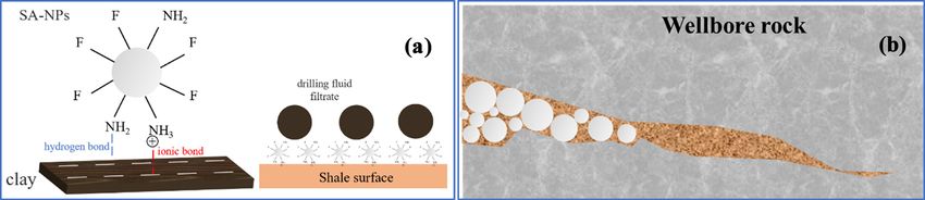
Figure 13: The mechanism of using SA-NPs to improve shale stability. Adsorption and wetting characteristics of SA-NPs on the shale surface
(a) and plugging function of SA-NPs (b).
drilling process, and can properly face various complex factors may bring a decrease in wellbore rock strength
formations, such as salt-gypsum formation. and the destruction of the stress balance, resulting in well-
bore instability [42]. Modified by amine groups, the surface
of SA-NPs could be attached strongly to the shale surface
through ionic bonding and hydrogen bonding [43]. Due to its
3.6 Mechanism analysis nanoscale “coalesce” structure, the shale surface adsorbed
with SA-NPs would exhibit a nano-papillary structure, sig-
Generally, shale is rich in clay minerals and exhibits nificantly improving its surface roughness at the nano-micro
strong amphiphilicity. Meanwhile, given lots of nano- scale. Coupled with the presence of ultra-low surface energy
micro pores and cracks on its surface, its strong capillary components (halothane segments), the SA-NPs-treated
self-priming effect [41] allows the drilling fluid filtrate to shale exhibited super-amphiphobic surface property,
easily penetrate the shale through pores and cracks under thus avoiding the binding of water molecules to clay
the bottom hole pressure difference and capillary force. minerals and preventing the penetration of drilling fluid
Free water in the filtrate causes the hydration swelling of filtrate into the shale (Figure 13a). Also, since SA-NPs have
the clay minerals. At the same time, the oil-soluble com- sizes between 70 and 200 nm, they can plug the nano-
ponents such as lubricants, hydrophobic polymers, and micron pores and cracks on the shale surface through
mineral oil in the filtrate weaken the cohesion between bridging and accumulation to further avoid the invasion
clay mineral particles. Furthermore, the intrusion of filtrate of filtrate (Figure 13b). The addition of SA-NPs could
increases the pore pressure of wellbore rock, resulting in the further avoid the hydration swelling of wellbore rock,
expansion and widening of the original fractures. These inhibit the hydration dispersion of shale cuttings, and
Table 4: Drilling parameters of Well (A) and Well (B)
Well name ECD Expansion rate of wellbore diameter/% Drilling cycle/day Accidents during drilling
Well (A) 1.58–1.62 5.62 11.5 —
Well (B) 1.78–1.72 7.35 20.97 Peeling and block dropping, sticking, etc
Figure 14: Well logging data of Well (A) and Well (B).52 Xuwu Luo et al.
prevent the transmission of filtrate pressure, improving the and used to enhance the wellbore stabilization per-
wellbore rock strength and stability. formance of WBDFs.
(2) SA-NPs could be adsorbed on the surface of shale to
form a nano-micro scale rough structure, which alters
the wettability of the shale surface and the direction of
4 Field application capillary force and prevents the water/oil phase from
intruding into the shale.
Well (A), located in the fault nose structure of Liujianfang (3) By adding 1 wt% SA-NPs, the WBDFs showed great
area in Dagang Oilfield, is a horizontal well for target improvement in linear swelling test, hot-rolling recovery
reservoir Ban 4. Given safety concerns in drilling through experiment, plugging rate test, and HTHP uniaxial com-
troublesome Sha 1 shale formations, the operation used pressive strength test.
KCl/PHPA drilling fluid first. Nevertheless, when the dril- (4) The application in Dagang Oilfield further proved
ling operation reached the upper shale formation of Sha 1, that WBDFs with SA-NPs could address wellbore
serious peeling and block dropping occurred, leading to instability in shale formation and have a good appli-
complex situations such as borehole diameter expanding, cation prospect.
sticking, and wellbore collapse. To prevent further dete-
rioration of the wellbore instability, many efforts such as
increasing the amount of amino-based inhibitor, asphalt
powder, and raising mud density were made, but the Nomenclature
results remained grim.
Based on the excellent shale stabilization performance, API American Petroleum Institute
SA-WBDFs were selected as the drilling fluid for continuous AV apparent viscosity
drilling in this section. As shown by the results of the real- CaCl2 calcium chloride
time drilling monitor, the peeling and block dropping issues ECD equivalent circulating density
were apparently reduced after changing KCl/PHPA drilling Eq equation
fluid with SA-WBDFs. Finally, the Sha 1 formation was FL filtration volume
drilled successfully, during which no wellbore instability, ht final height of shale cuttings pellet after
sticking, and other complex situations occurred. The dril- immersed in test liquids for a certain time
ling parameters and well logging data of Well (A) using SA- h0 initial height of shale cuttings pellet
WBDFs and Well (B) using PHPA/KCl drilling fluid in the HTHP high-temperature and high-pressure
same work area are shown in Table 4 and Figure 14. As IEDFs invert emulsion drilling fluids
shown in Table 4, compared to adjacent Well (B) that KCl/PHPA potassium chloride/partially hydrolyzed
used PHPA/KCl as drilling fluid, Well (A) had a smaller polyacrylamide
drilling cycle but equivalent circulating density (ECD) and Ki permeability of the original shale core
expansion rate of wellbore diameter and encountered no Kp permeability of the shale core contaminated
downhole problems. In further comparison, as shown in with drilling fluids
the logging data in Figure 14, Well (A) has a smaller dia- m1 remaining mass of the shale cuttings
meter change and a more regular borehole. The difference m0 original mass of the shale cuttings
was caused by the use of SA-WBDFs that reversed the wett- NaCl sodium chloride
ability of the rock surface of Sha 1 formation, avoided the pc capillary force
capillary self-priming effect, and effectively plugged the PDMDAAC poly dimethyldiallyl ammonium chloride
pores and cracks on the wellbore rock surface, thereby sig- Pr plugging rate
nificantly minimizing the negative impact of WBDFs on the PV plastic viscosity
wellbore rock strength. r capillary radius
SA-NPs super-amphiphobic nano-silica
nanoparticles
SEM scanning electron microscopy
5 Summary and conclusions SiO2 fumed silica nanoparticles
TEM transmission electron microscopy
(1) Aiming at the wellbore instability issue in drilling WBDFs water-based drilling fluids
shale wells, SA-NPs were investigated systematically w/v weight/volumeNovel approach to improve shale stability using SA-NPs 53
YP yield point [5] Fan, X., M. Zhang, Q. Zhang, P. Zhao, B. Yao, and D. Lv.
ρ density Wellbore stability and failure regions analysis of shale for-
σ surface tension of deionized water mation accounting for weak bedding planes in ordos basin.
Journal of Natural Gas Science and Engineering, Vol. 77, 2020,
θ contact angle of capillary inner surface
id. 103258.
θ600 Dial readings of the viscometer at 600 rpm [6] Li, X., G. Jiang, J. Wang, and X. Ni. Inhibitive properties com-
θ300 Dial readings of the viscometer at 300 rpm parison of different polyamino acids in water-based drilling
fluids. Journal of Natural Gas Science and Engineering, Vol. 83,
2020, id. 103589.
Acknowledgements: The authors would like to acknowl- [7] Huang, W., H. Zhong, J. Cao, and Z. Qiu. Poly (oxypropylene)-
edge financial support from the National Natural Science amidoamine modified bentonite as potential shale inhibitor in
Foundation of China. water-based drilling fluids. Applied Clay Science, Vol. 67–68,
2012, pp. 36–43.
[8] Anderson, R. L., I. Ratcliffe, H. C. Greenwell, P. A. Williams,
Funding information: This work was supported by the
S. Cliffe, and P. V. Coveney. Clay swelling – a challenge in the
National Natural Science Foundation (Grant No. 51874329 oilfield. Earth Science Reviews, Vol. 98, No. 3, 2010,
and Grant No. 51991361) and the National Natural Science pp. 201–216.
Innovation Population of China (Grant No. 51821092). [9] Leite, R. S., A. P. T. Dantas, and L. V. Amorim. Influence of clay
swelling inhibitor in filtration properties of water-based dril-
ling fluids. Materials Science Forum, Vol. 869, 2016,
Author contributions: Xuwu Luo: conceptualization, meth-
pp. 1018–1022.
odology, investigation, data curation, formal analysis, and [10] Kelly, J. Drilling fluids selection, performance, and quality
writing – original draft; Guancheng Jiang: methodology, control. Journal of Petroleum Technology, Vol. 35, No. 5, 1983,
project administration, supervision, resources, and writing – pp. 889–898.
original draft; Guoshuai Wang: methodology, resources, and [11] Zhou, L., J. Feng, J. Lei, and J. Yuan. Experimental application
writing – review and editing; Lili Yang: supervision, concep- of salt slurry in zhongyuan high density polymer saturated
brine-based drilling fluid. Advanced Materials Research,
tualization, and writing – review and editing; Yinbo He:
Vol. 335–336, 2011, pp. 1348–1351.
methodology; Kaixiao Cui: writing – review and editing; [12] Guo, J., J. Yan, W. Fan, and H. Zhang. Applications of strongly
Jun Yang: writing – review and editing. inhibitive silicate-based drilling fluids in troublesome shale
formations in sudan. Journal of Petroleum Science and
Conflict of interest: There are no conflicts to declare. Engineering, Vol. 50, No. 3, 2006, pp. 195–203.
[13] Xiong, Z., S. Tao, X. Li, W. Shan, and H. Dong. Development
and application of anti-collapse & anti-drag agent for drilling
Data availability statement: The data used to support the fluid. Procedia Engineering, Vol. 73, 2014, pp. 55–62.
findings of this study have not been made available [14] Cao, J., T. Song, Y. Zhu, S. Wang, X. Wang, F. Lv, et al.
because they also form part of an ongoing study. Application of amino-functionalized nanosilica in improving
the thermal stability of acrylamide-based polymer for
enhanced oil recovery. Energy & Fuels, Vol. 32, No. 1, 2017,
pp. 246–254.
[15] He, Y., G. Jiang, and W. Cui. Salt-responsive AM/AMPS/ATC
References terpolymers as modifiers for rheology and fluid loss in water-
based drilling fluid. Key Engineering Materials, Vol. 765, 2018,
[1] Li, M., Q. Wu, J. Han, C. Mei, T. Lei, S. Lee, et al. Overcoming pp. 106–112.
salt contamination of bentonite water-based drilling fluids [16] He, Y., G. Jiang, Z. Deng, F. Liu, S. Peng, X. Ni, et al.
with blended dual-functionalized cellulose nanocrystals. ACS Polyhydroxy gemini surfactant as a mechanoresponsive
Sustainable Chemistry & Engineering, Vol. 31, No. 8, 2020, rheology modifier for inverted emulsion drilling fluid. RSC
pp. 11569–11578. Advances, Vol. 8, 2018, pp. 342–353.
[2] Ross, D. J. K. and R. M. Bustin. The importance of shale com- [17] Huang, X., G. Jiang, Y. He, Y. An, and S. Zhang. Improvement of
position and pore structure upon gas storage potential of rheological properties of invert drilling fluids by enhancing
shale gas reservoirs. Marine & Petroleum Geology, Vol. 26, interactions of water droplets using hydrogen bonding linker.
No. 6, 2009, pp. 916–927. Colloids and Surfaces A Physicochemical and Engineering
[3] Curtis, J. B. Fractured shale-gas systems. AAPG Bulletin, Aspects, Vol. 506, 2016, pp. 467–475.
Vol. 86, No. 11, 2002, pp. 1921–1938. [18] Mao, H., Y. Yang, H. Zhang, J. Zheng, and Y. Zhong. Conceptual
[4] Labani, M. M., R. Rezaee, A. Saeedi, and A. A. Hinai. Evaluation design and methodology for rheological control of water-
of pore size spectrum of gas shale reservoirs using low pres- based drilling fluids in ultra-high temperature and ultra-high
sure nitrogen adsorption, gas expansion and mercury porosi- pressure drilling applications. Journal of Petroleum Science
metry: a case study from the perth and canning basins, wes- and Engineering, Vol. 188, 2020, id. 106884.
tern australia. Journal of Petroleum Science & Engineering, [19] Wang, K., G. Jiang, X. Li, and P. F. Luckham. Study of graphene
Vol. 112, 2013, pp. 7–16. oxide to stabilize shale in water-based drilling fluids. Colloids54 Xuwu Luo et al.
and Surfaces A Physicochemical and Engineering Aspects, tional anti-corrosion coating and a superamphiphobic coating.
Vol. 606, 2020, id. 125457. Chemical Engineering Journal, Vol. 390, 2020, id. 124562.
[20] Jiang, G., K. Wang, Y. He, L. Yang, and Y. Deng. Synthesis of an [34] Yuan, R., S. Wu, H. Wang, L. Hu, Y. Zhu, S. Gao, et al. Facile
amphoteric polymer as a high-temperature-resistant shale fabrication approach for a novel multifunctional superamphi-
stabilizer in water-based drilling fluids. Journal of Applied phobic coating based on chemically grafted montmorillonite/
Polymer Science, Vol. 137, No. 35, 2020, id. 49016. Al2O3-polydimethylsiloxane binary nanocomposite. Journal of
[21] Wong, W. S. Y. Surface chemistry enhancements for the tun- Polymer Research, Vol. 24, No. 4, 2017, id. 10965.
able super-liquid repellency of low-surface-tension liquids. [35] Hu, M., H. J. Butt, K. Landfester, M. B. Bannwarth, S. Wooh, and
ACS AuthorChoice, Vol. 19, No. 3, 2019, pp. 1892–1901. H. Thérien-Aubin. Shaping the assembly of superparamagnetic
[22] Safari, M., R. Gholami, C. X. Liew, A. Raza, and nanoparticles. ACS AuthorChoice, Vol. 13, No. 3, 2019, pp. 3015–3022.
J. V. Vettaparambil. A new mud design to reduce formation [36] Wan, Y., L. Xu, Z. Liu, and H. Yu. Fabrication of a super-
damage in sandstone reservoirs. Journal of Petroleum Science amphiphobic aluminium alloy surface via wire electrical dis-
and Engineering, Vol. 181, 2019, id. 106221. charge machining and chemical etching technology. IET Micro
[23] Shi, Y., S. Chen, Y. Peng, J. Song, and J. Cai. Experimental & Nano Letters, Vol. 12, No. 3, 2017, pp. 175–178.
study on synergistically enhancing the wellbore stability of [37] Sheen, Y. C., Y. Huang, C. Liao, H. Chou, and F. Chang. New
coal measure strata by electrical inhibition and neutral wet- approach to fabricate an extremely super-amphiphobic sur-
ting. Meitan Xuebao/Journal of the China Coal Society, Vol. 43, face based on fluorinated silica nanoparticles. Journal of
No. 6, 2018, pp. 1701–1708. Polymer Science Part B Polymer Physics, Vol. 46, No. 18, 2010,
[24] Shi, Y., S. Chen, X. Yang, L. Yu, and J. Cai. Enhancing wellbore pp. 1984–1990.
stability of coal measure strata by electrical inhibition and [38] Wang, H., H. Zhou, H. Niu, J. Zhang, Y. Du, and T. Lin. Dual-
wettability control. Journal of Petroleum Science and layer superamphiphobic/superhydrophobic-oleophilic nano-
Engineering, Vol. 174, 2019, pp. 544–552. fibrous membranes with unidirectional oil-transport ability
[25] Xu, J., Z. Qiu, X. Zhao, and W. Huang. Hydrophobic modified and strengthened oil-water separation performance. Advanced
polymer-based silica nanocomposite for improving shale sta- Materials Interfaces, Vol. 2, No. 4, 2015, id. 1400506.
bility in water-based drilling fluids. Journal of Petroleum [39] Zhang, Y., H. Xia, E. Kim, and H. Sun. Recent developments in
Science and Engineering, Vol. 153, 2017, pp. 325–330. superhydrophobic surfaces with unique structural and func-
[26] Yue, Y., S. Chen, Z. Wang, X. Yang, Y. Peng, J. Cai, et al. tional properties. Soft Matter, Vol. 8, No. 44, 2018,
Improving wellbore stability of shale by adjusting its wett- pp. 11217–11231.
ability. Journal of Petroleum Science and Engineering, Vol. 161, [40] Lu, Y., S. Sathasivam, J. Song, C. R. Crick, and I. P. Parkin.
2018, pp. 692–702. Robust self-cleaning surfaces that function when exposed
[27] Cheraghian, G., M. Hemmati, and S. Bazgir. Application of TiO2 to either air or oil. Science, Vol. 347, No. 6225, 2015,
and fumed silica nanoparticles and improve the performance pp. 1132–1135.
of drilling fluids. AIP Conference Proceedings, American [41] Ni, X., G. Jiang, F. Liu, and Z. Deng. Synthesis of an amphi-
Institute of Physics, 2014, pp. 266–270. phobic nanofluid with a novel structure and its wettability
[28] Cheraghian, G. Nanoparticles in drilling fluid: A review of the alteration on low-permeability sandstone reservoirs. Energy &
state-of-the-art. Journal of Materials Research and Fuels, Vol. 32, No. 4, 2018, pp. 4747–4753.
Technology, Vol. 13, No. 11, 2021, pp. 737–753. [42] Ni, X., G. Jiang, Y. Li, L. Yang, W. Li, K. Wang, et al. Synthesis of
[29] Ikram, R., B. M. Jan, A. Sidek, and G. Kenanakis. Utilization of eco- superhydrophobic nanofluids as shale inhibitor and study of
friendly waste generated nanomaterials in water-based drilling the inhibition mechanism. Applied Surface Science, Vol. 484,
fluids; state of the art review. Materials, Vol. 14, No. 15, 2021, id. 4171. 2019, pp. 957–965.
[30] Ahmed, W., M. Booth, and E. Nourafkan. Emerging nano- [43] Jiang, G. Gas wettability of reservoir rock surfaces with porous
technologies for renewable energy. Chapter 6 - media, Gulf Professional Publishing, Cambridge, MA, 2018.
Nanotechnology for drilling operations, ed. G. Cheraghian, [44] Guo, X., Y. Zhang, and X. Cheng. In-situ fluorinating silica
Afrand, M., Elsevier Inc, Amsterdam, 2021, 135-148 nanoparticles for superamphiphobic coating preparation.
[31] Schmüser, L., N. Encinas, M. Paven, D. J. Graham, Journal of The Chinese Ceramic Society, Vol. 48, No. 1, 2020,
D. G. Castner, D. Vollmer, et al. Candle soot-based super- pp. 128–134.
amphiphobic coatings resist protein adsorption. [45] Feng, X. and L. Jiang. Design and creation of superwetting/
Biointerphases, Vol. 11, No. 3, 2016, id. 031007. antiwetting surfaces. Advanced Materials Technologies,
[32] Huang, Y., Z. Wang, D. Hou, and S. Lin. Coaxially electrospun Vol. 18, No. 23, 2006, pp. 3063–3078.
super-amphiphobic silica-based membrane for anti-surfac- [46] Yang, L., G. Jiang, Y. Shi, X. Lin, and X. Yang. Application
tant-wetting membrane distillation. Journal of Membrane of ionic liquid to a high-performance calcium-resistant addi-
Science, Vol. 531, 2017, pp. 122–128. tive for filtration control of bentonite/water-based drilling
[33] Wei, J., B. Li, L. Jing, N. Tian, X. Zhao, and J. Zhang. Efficient fluids. Journal of Material Science, Vol. 52, 2017,
protection of mg alloy enabled by combination of a conven- pp. 6362–6375.You can also read


