Novel hybrid method to additively manufacture denser graphite structures using Binder Jetting - Nature
←
→
Page content transcription
If your browser does not render page correctly, please read the page content below
www.nature.com/scientificreports
OPEN Novel hybrid method to additively
manufacture denser graphite
structures using Binder Jetting
Vladimir Popov1*, Alexander Fleisher1, Gary Muller‑Kamskii1,2, Andrei Shishkin3,4,
Alexander Katz‑Demyanetz1, Nahum Travitzky5 & Saurav Goel6,7,8
This study introduces two hybrid processes integrating an additive manufacturing technique
with post-processing treatments namely (i) Binder Jetting Printing (BJP) + Cold Isostatic Pressing
(CIP) + cycle and (ii) BJP + cycle where cycle refers to a sequence of Impregnation—Drying—Pyrolysis.
These two new processes yielded additively manufactured parts with higher density and reduced
defects/porosities. As a testbed, we used these new processes to fabricate graphite structures. The
samples produced by both methods were compared with each other and benchmarked to the samples
produced by (a) BJP alone and (b) Traditional uniaxial pressing like compaction moulding. Various
characterisation methods were used to investigate the microstructure and mechanical properties
which showed that the porosity of hybrid manufactured samples reduces from 55% to a record 7%.
This technological pathway is expected to create a new avalanche of industrial applications that are
hitherto unexplored in the arena of hybrid additive manufacturing with BJP method.
Graphite is a widely used material in various industrial applications due to its thermal stability at elevated tem-
peratures, chemical resistance to aggressive aqueous solutions and high electrical conductivity1. Some of the
common industrial examples of this includes manufacturing of melting crucibles, heating elements as well as in
the processing of the bow of ballistic missiles and spacecraft for thermal p rotection2 and for the production of
various elements and tools of electric machines (brushes), electric vehicles and pumping equipment (e.g. blades)3.
Mechanically stable graphite products are traditionally produced using the powder metallurgy technique
which relies on using graphite powder and a binder. The binder is a “glue” that bonds the powder’s particles
together. In traditional manufacturing, upon heating (e.g. coal resin or petroleum pitch) the binder softens,
allowing a uniform wetting and homogenous adhesion of the graphite powder. The resulting blend after milling
or grinding moves to the next production steps such as moulding, compaction or extrusion.
Polymer-bonded graphite is popularly used for tribological applications. These are used in high production
volumes and thus, they turn out to be low cost and can easily be produced in complex desirable s hapes4.
The three main production techniques (see Fig. 1) for graphite structures having different final material
properties are (i) isostatic pressing (moulding)—where graphite powder mixture is pressed isostatically (ii)
extrusion—where graphite powder mixture is pushed through a die and (iii) uniaxial compaction (moulding)
where graphite powder is pressed in one direction (e.g. for manufacturing graphite cylinders)5.
The control over the density of graphite components is crucial, since density plays a vital role in influencing
the strength and many other functional characteristics of the component. Insufficient density of the green-bodies
may cause post-processing troubles, reduced strength and low wear r esistance6–8.
Usually carbon-based materials are used as reinforcements in additively manufactured metallic p arts9–11 and
composites12,13. Most of the conventional components of carbon and its derivatives are made through traditional
subtractive manufacturing processes. Owing to the inability of current subtractive technologies to produce com-
plex-shaped graphite parts with desired microstructures and properties, novel additive processing techniques,
1
Israel Institute of Metals, Technion, Israel Institute of Technology, 3200003 Haifa, Israel. 2Heat Treatment and
Physics of Metals Department, Ural Federal University, Ekaterinburg, Russia. 3Rudolfs Cimdins Riga Biomaterials
Innovations and Development Centre of RTU, Institute of General Chemical Engineering, Faculty of Materials
Science and Applied Chemistry, Riga Technical University, Riga 1007, Latvia. 4Maritime Transport Department,
Latvian Maritime Academy, Riga 1016, Latvia. 5Department of Materials Science and Engineering, Institute of
Glass and Ceramics, University of Erlangen-Nuremberg, 91058 Erlangen, Germany. 6School of Engineering,
London South Bank University, London SE10AA, UK. 7School of Aerospace, Transport and Manufacturing,
Cranfield University, Cranfield MK43 0AL, UK. 8Department of Mechanical Engineering, Shiv Nadar University,
Gautam Budh Nagar 201314, India. *email: vvp@technion.ac.il
Scientific Reports | (2021) 11:2438 | https://doi.org/10.1038/s41598-021-81861-w 1
Vol.:(0123456789)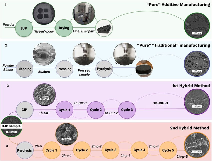
www.nature.com/scientificreports/
Figure 1. Production techniques for graphite structures (left) isostatic pressing or moulding (middle) extrusion
and (right) uniaxial compaction.
such as Selective Laser Sintering (SLS), Stereolithography (SLA), Laminated Object Manufacturing (LOM) and
Binder Jetting Printing (BJP) have been seen to emerge during the last two decades. These techniques offers
capability to fabricate ceramic bodies with complex g eometry14–18.
The stereolithography method uses laser/light projection and photopolymerization processes for fabricating
multimaterial heterogeneous s tructure9,10. The thermoset material is utilised as a matrix for powder reinforced
materials. Reported data shows that carbon-containing composites could be manufactured using graphite pow-
der, graphene, and carbon nanotubes by SLA-like 3D p rinting10.
Another technique, LOM is used for papers, polymers and metals. The LOM process can be used to produce
ceramic (e.g. A l2O3, Si3N4, and SiC with graphitic powder/carbon fibers) p apers11.
SLS enables additive manufacturing of carbon-containing structures by working with material mixing.
For example, the SiC powder, short carbon fibers and epoxy resin are ball-milled and then processed by SLS.
The printed parts can be carbonized and then infiltrated with molten silicon to obtain reaction bonded SiC
structures12. Other Powder Bed Fusion (PBF) techniques, like Selective Laser Melting (SLM) and Electron Beam
Melting (EBM) cannot be used for ceramics manufacturing. These techniques are applied to metals, and in some
cases to reinforced alloys and metal matrix composites13–16.
The unique benefit of BJP in comparison to the Powder Bed Fusion techniques is its capability to process
virtually any powder including graphite, ceramics and refractory alloys17. Here, the binder can be removed from
the printed green part by drying which then leaves behind an unbonded green porous p art18–21.
Attempts have recently been made to apply BJP to manufacture graphite-based structures with required
physical properties18–20,22,23. One of the advantages of the BJP process is the capability to achieve the required
density and mechanical performance using typical post-processing such as the reaction sintering or liquid metal
infiltration22,24,25. The limited reported data about the possible density of graphite and carbon-containing mate-
rials by BJP shows for instance that the part density of graphene-based electrodes processed by BJP was only
0.44 g/cm319. To the best of author’s knowledge, there is no other report about printing of high-density graphite
produced by the BJP method. The low flowability of irregular-shape graphite powders limits their effective use for
additive manufacturing since freshly printed structures have a large number of defects after powder deposition23.
The production-related porosity induced in the graphite materials (both in subtractive and additive manu-
facturing) results in a certain permeability to fluids which limits the use of such materials in applications i.e.
sealing elements.
Scientific Reports | (2021) 11:2438 | https://doi.org/10.1038/s41598-021-81861-w 2
Vol:.(1234567890)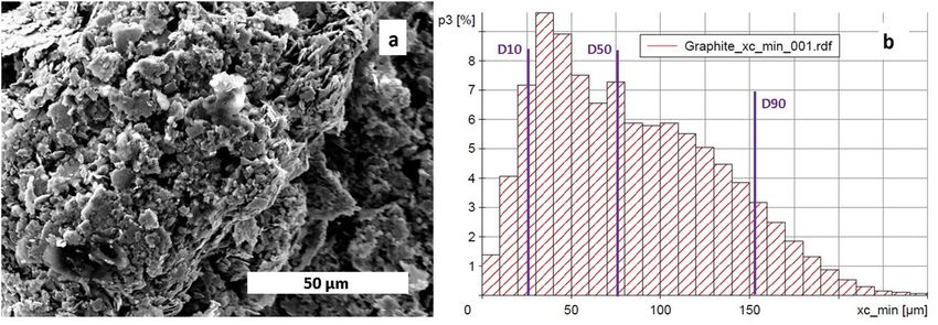
www.nature.com/scientificreports/
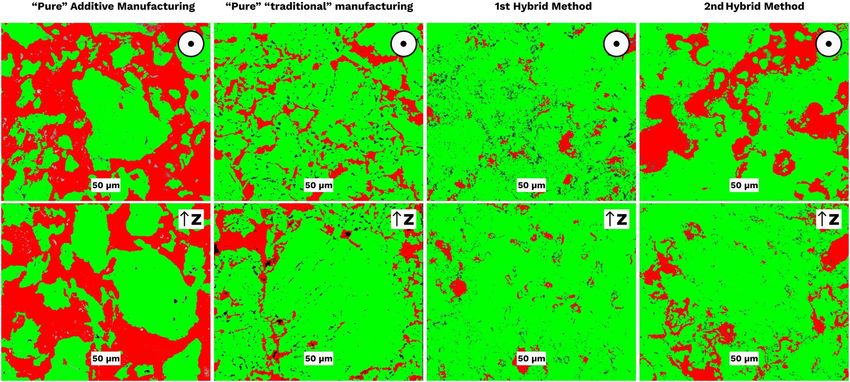
Figure 2. Process flow showing production of graphite using different production routes where BJP Binder
Jetting Printing, CM compacted moulding, CIP Cold Isostatic Pressing, Cycle is the sequence of Impregnation—
Drying—Pyrolysis.
In some cases, open porosity is required for reaction bonding and liquid infiltration treatment, which can
radically increase the d ensity18,22,25,26. In order to reduce the porosity of the fabricated samples, and to increase
the density of the final material, post impregnation can be used4,18,22.
Overall, BJP is clearly the most promising technique for fabricating carbon-based and graphite parts due to
the possibility of incorporating intelligent functions like heating and thermal management. Also, the components
manufactured using BJP can be imbued with specific properties of graphite and carbon which includes mechani-
cal strength, light-weight, higher electrical and thermal conductivity and low thermal e xpansion21.
The present work was aimed at investigating the feasibility of producing additively manufactured low-poros-
ity/high-density graphite parts using the BJP technique combined with technologically necessary post treatments,
namely binder impregnation and pyrolysis. Cold isostatic pressing (CIP) was employed as an intermediate density
improvement method as an interim processing stage. The main research hypothesis in this research was that
there lies a tradeoff between the achievable density and the ease with which complex shapes can be fabricated so
a hybrid method can balance these requirements. The combination of techniques can lead to lower porosity and
improved mechanical and physical properties of complicated-shaped manufactured p arts27,28. Determination
of process critical steps and the parameters critical for achieving the density improvement were found which
are being reported in this work.
Methods and materials
Experimental scheme. Figure 2 illustrates the processing routes used in this work. The first line in Fig. 2
is devoted to the “purely” additive manufacturing stage using the BJP technique alone. As was explained above,
such a method enables production of complex geometrical structures, however the porosity of such parts is high
(~ 50–60%), and their density is low22,24,29. The second route involved uniaxial pressing (compaction moulding)
and was performed purely to illustrate the density/porosity achievable from the “traditional” route (CM-sam-
ples). In the third and fourth lines, we illustrate two new methods starting from BJP and then using secondary
techniques of treatments. The BJP processed part can either be CIPed after printing and then passed through
three cycles of binder impregnation and pyrolysis (1 h-samples—1st hybrid method) or can be routed via five
Scientific Reports | (2021) 11:2438 | https://doi.org/10.1038/s41598-021-81861-w 3
Vol.:(0123456789)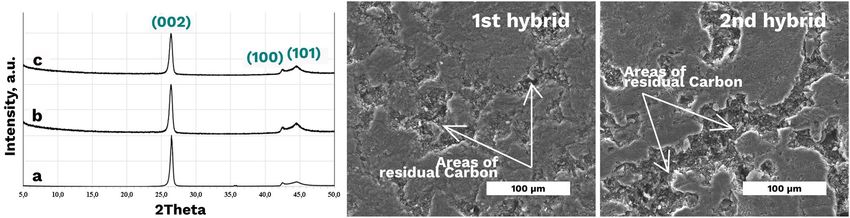
www.nature.com/scientificreports/
Figure 3. (a) Scanning electron microscopy (SEM) image showing graphite powder morphology and (b)
Particle size distribution of the graphite powder used.
cycles of pyrolysis and impregnation (2 h-samples—2nd hybrid method). Overall, the objective was to com-
bine the advantages of AM (freedom of design) and traditional manufacturing (high-density). As a testbed, we
fabricated a complex-shaped part which was processed further by the 2nd hybrid method. This part was in the
form of a 50 mm-side hexagonal mirror. The height of the inner ribs was 4 mm, their thickness was 1.5 mm. The
thickness of the outer plane was 2.5 mm.
Through the manufacturing experiments, a total of ten rectangular prism-shaped samples (18 × 14.5 × 6 mm3)
were printed for the microstructural analysis and mechanical testing. We observed that the geometry of the part
arts30,31. The rectangular prism shape for BJP samples were selected
has no influence on the density of the green p
for further characterization. The CM samples had a cylindrical shape (d = 30 mm, h = 7 mm) due to the moulding
die dimensions. The hybrid manufactured 1 h- and 2 h-samples initially had the same size and prism bar-shape
as BJP ones since the new processes start after the BJP process.
Binder Jetting Printing (BJP). Specimens for the current study were manufactured using BJP ExOne
M-Flex machine (ExOne, USA). The graphite powder with purity of > 98% and an average particle size of 80 µm
was used. The morphology of the powder and particle size distribution obtained prior to the study are shown in
Fig. 3a,b. The reason for use of BJP was due to the advantages of sample shaping. Unlike other methods, the BJP
method does not require a rigid die for sample preparation32. Moreover, BJP can produce geometrically complex
parts free from residual stresses and with controlled porosity24.
In carrying out the BJP, a commercial ExOne phenolic binder was used, this was because the phenolic binder
after debinding leaves residual carbon in as print specimen22. The binder density according to technical docu-
mentation was ρb = 0.94 g/cm3. The BJP parameters used were layer thickness of 100 μm, powder bed temperature
of about 44 °C and layer drying speed of 25 mm s−1.
The BJP printing settings include binder saturation S—a quantitative parameter of binder amount in pores.
For the experiments, S was 60%. This means that after the BJP process, 60% of pores were filled by the binder
while 40% were empty voids. The powder packing rate was 60%. The volume of binder in printed structures can
be calculated using the following equation:
S = Vb / Vp , (1)
where Vb stands for volume of binder and Vp for pores’ v olume33.
For example, for a 1 cm3 cube sample: Vp = 40% = 0.4 cm3; Vb = 0.4 × 0.6 = 0.24 cm3; layer thickness 100 μm;
binder mass for the sample is mb = Vb × ρb = 0.226 g; the mass of binder in one layer mb/l = 2.26 mg/cm2.
Layer thickness for all experiments was maintained to be the same i.e. 100 μm. This parameter is flexible
and can be changed depending on product requirements. The machine’s software uses layer thickness value for
automatic calculation of the binder saturation.
The printed envelope volume VPE is defined as:
VPE = Xd × Yd × layer thickness (Zd )31 , (2)
where Xd and Yd are the corresponding distances between successive droplets in X and Y directions respectively.
Zd is the current building height. From (2), a direct relation between the layer thickness and the binder satura-
tion is evident and this is the reason behind "green" body’s mechanical properties and dimensional a ccuracy31.
Drying, impregnation and pyrolysis. After BJP, the samples were dried in the furnace for 2 h at 200 °C. It
has been shown that the density of printed preforms can be increased by impregnation of phenolic r esin4,34. Phe-
nolic binder is advantageous for this purpose because the residual carbon after debinding (pyrolysis) partially
fills the pores. This treatment is called Phenolic Resin Binder Impregnation (PRBI)22. In this work, all impregna-
tions were carried out using the same phenolic binder that was used for the Binder Jetting Printing.
Scientific Reports | (2021) 11:2438 | https://doi.org/10.1038/s41598-021-81861-w 4
Vol:.(1234567890)www.nature.com/scientificreports/
Figure 4. Image analysis of optical microscopy images of crosscuts in XY- and Z-planes. The black arrow points
at the build/pressing direction (Z), i.e., perpendicular to the layers; the black circle with the point in the center
corresponds to XY plane–parallel to layers.
For impregnation, the BJP samples after drying were placed in the binder at room temperature for 1 h under
reduced pressure.
Before pyrolysis, the impregnated samples were dried under the same conditions i.e. 2 h at 200 °C in electric
muffle Nabertherm furnace (Germany). The pyrolysis was carried out using argon at 1000 °C for an hour.
Cold isostatic pressing (CIP). Before CIP treatment, the printed graphite samples were vacuum packed in
polyethylene bags. They were then isostatically pressed at 106 MPa for 1 min at room temperature.
Compaction moulding. To compare the possible densification of the BJP-made samples, additional sam-
ples were manufactured by compaction moulding with the same phenolic binder. An experimental ratio of
binder amount to powder of 1:3 was used corresponding to the amount of binder (Vb = 24%) in the BJP process.
The mixture was prepared using a blending machine. It was uniaxially pressed using a laboratory press for
20 min under 20 MPa.
Microstructure and phase composition analysis. The samples were prepared using epoxy mounting
and standard polishing with abrasive papers and SiO2 finishing.
The scanning electron microscopy analysis was performed by SEM FEI Inspect (FEI, Brno, Czech Republic)
equipped with Electron Probe Micro Analyzer (EPMA). A Back-Scattered Electrons Detector was used to obtain
phase contrast. The acceleration voltage and working distance used were 20 kV and 9–11 mm, respectively.
A Nikon Eclipse LV150 (Japan) microscope was used for the optical analysis. Image analysis was conducted
using Olympus Stream Essentials software.
X-rays diffraction (XRD) was employed to examine the phase content of as built vs the impregnated samples.
Stationary Rigaku Smart Lab diffractometer (Tokyo, Japan) equipped with a Cu tube (λKα = 1.5406 Å) was used.
The scattering range (2θ) was 5 ÷ 50°.
Microhardness HV10 evaluation was performed using a Vickers Hardness Tester FV-110 as discussed
elsewhere35.
Results and discussions
The two main characteristics of the fabricated parts to be evaluated from the additional analysis made were
porosity and density and the mechanical properties, these are discussed next.
Porosity and density of the parts. Figure 4 shows a comparison of the porosity in (i) the green-body
after pure additive manufacturing (BJP alone), (ii) uniaxially pressed sample (CM), (iii) BJP + CIP and 3 impreg-
nation cycles (1st hybrid) and (iv) BJP + pyrolysis + 5 impregnation cycles (2nd hybrid).
Figure 4 shows the influence of the treatments revealing the variation in the porosity of the fabricated sam-
ples. It can be observed that the 1st hybrid sample showed reduced volume fraction of porosity compared to
all other methods. It can be observed that in the “green” printed samples, the porosity level was comparable to
one with the freely poured powder (correspondingly BJP and S0 samples in Table 1). As shown in Fig. 4, in the
1st hybrid method, the dense phase formed homogeneously in both directions. Further calculations shown in
Table 1 confirmed this aspect quantitatively. In Table 1 are presented the porosity level (column Pores, %) and the
Scientific Reports | (2021) 11:2438 | https://doi.org/10.1038/s41598-021-81861-w 5
Vol.:(0123456789)www.nature.com/scientificreports/
Volume fraction of
Sample Plane Pores, % Standard deviation Powder, % Standard deviation
S0 (powder) – 59.82 2.45 36.13 2.56
z 48.98 0.74 49.13 1.13
BJP (“green”-body)—Pure Additive
xy 56.24 2.05 40.67 2.12
z 15.21 1.53 81.12 1.78
CM (compaction moulded)—Traditional
xy 15.69 1.52 80.33 1.92
z 7.32 1.64 88.72 2.20
1 h-CIP-3 (1st hybrid)
xy 7.34 1.20 90.83 1.97
z 18.91 1.27 79.13 1.6
2 h-p-5 (2nd hybrid)
xy 18.76 1.78 77.61 2.40
Table 1. Image analysis showing volume fraction of porosity “green”, under treated, and isostatically pressed
samples.
percentage of the dense part (column Powder, %). The column "Powder, %" shows that the 2nd hybrid method
provides a similar density as compaction moulding. Moreover, the 1st hybrid method demonstrates even higher
density. The values shown here are averaged using 3 images in each plane.
The initial porosity level achieved from the BJP made green-body samples (S1) was higher than 50%. The 1st
hybrid method with post CIPing lead to the highest densification of the printed samples with an average poros-
ity of 7%. The significant pore closure resulted in the shrinkage which is typical in ceramic manufacturing. For
BJP made graphite, volumetric shrinkage of about 20% was observed. The 2nd hybrid method with the use of
impregnation and pyrolysis cyclic route decreases the porosity up to 18%.
Since the starting density is similar in the BJP and hybrid starting samples, the density evolution rate is
dependent on the pyrolyzed residual graphite mass added in each cycle. However, it should be taken into account
that after a certain number of cycles of phenolic reaction binder impregnation (PRBI) and pyrolysis, the density
improvement is limited because of the formation of a dense layer near the surface of the sample that prevents
further carbonization36.
As shown in Fig. 5, the hybrid graphite structures became denser with the successive PRBI and pyrolysis
cycles. The density was observed to depend on the fabrication method and on the number of cycles. The proxim-
ity in the value of density was confirmed by calculations (see Table 2, Fig. 5).
The density of samples was calculated through weight measurement (see Table 2, Fig. 5). As can be seen
from Table 2 and Fig. 5, the 2nd hybrid sample had 96% bulk density compared to compaction moulded sample
(CM). The 1st hybrid sample that passed CIP had even higher density—1.38 g/cm3 accounting for 100% density
of the reference sample (CM).
One key drawbacks of the above-mentioned BJP process in the production of graphite-based structures is
the large amount of residual porosity, a possible method of improvement is offered by CIP before the binder
impregnation cycles.
Figure 6 shows the degree of similarity between the microstructure of the samples fabricated by BJP with
post-CIPing and resin impregnation (1st hybrid) and compaction moulding. That corresponds to density meas-
urements in Fig. 5.
XRD examination. The XRD examination of the as-built (BJP) and highly impregnated 1st and 2nd hybrid
specimens (Fig. 7a) did not reveal any new crystalline and amorphous phases aroused from impregnation.
Therefore, the impregnation-induced graphite phase had a crystallographic structure corresponding to that of
the matrix graphite phase.
The samples CM, 1 h-CIP-3 and 2 h-p-5 were final samples from each of the following manufacturing routes:
compaction moulding (CM), 1st hybrid method (BJP after CIP and three cycles of PRBI and pyrolysis), and 2nd
hybrid method (BJP after 5 cycles of PRBI and pyrolysis).
From Fig. 7, it can be observed visually that the initial porosity of the 2nd hybrid sample 2 h-p-5 still remains.
However, the pores already filled with residual carbon due to PRBI and pyrolysis treatment. The 1st hybrid
1 h-CIP-3 sample has a lower initial porosity and due to this fact, the lower amount of residual carbon is required
to fill the pores and thus increase density.
Microhardness measurements. Microhardness measurements of green samples revealed a homogene-
ous microhardness of about of HV10 233.8 MPa (see Fig. 8).
An impregnation frequency of five times followed by pyrolysis resulted in a density improvement from 0.94
to 1.31 g/cm3 without causing any microhardness increase. This result may be explained by lower hardness of
the impregnated carbon comparable to the as-printed graphite. Samples produced by the 1st hybrid method
demonstrated higher microhardness than those undergoing only impregnation/pyrolysis treatment, but their
homogeneity from the point of view of microhardness remained low. Obviously, additional heat treatment is
required to improve the homogeneity of CIPed samples.
Scientific Reports | (2021) 11:2438 | https://doi.org/10.1038/s41598-021-81861-w 6
Vol:.(1234567890)www.nature.com/scientificreports/
Figure 5. Dependence of the hybrid and compacted samples density on the number of pyrolysis cycles. 2nd to
6th pyrolysis was applied after PRBI. For compacted sample as initial density is the density before pyrolysis.
Sample State Size (mm) Weight (g) Density (g/cm3)
S0 Powder – – 0.62
BJP Green-body 18 × 14.5 × 6 1.47 0.94
CM Compaction moulding and pyrolysis d = 30; h = 7 6.9 1.37
1 h-CIP BJP “green”-body after CIP 16 × 14 × 5.6 1.42 1.13
1 h-CIP-1 CIPed after Cycle 1 16 × 14 × 5.6 1.49 1.18
1 h-CIP-2 CIPed after Cycle 2 16 × 14 × 5.6 1.60 1.27
1 h-CIP-3 CIPed after Cycle 3 16 × 14 × 5.6 1.73 1.38
2 h-p BJP “green”-body after 1st pyrolysis 18 × 14.5 × 6 1.37 0.87
2 h-p-1 After Cycle 1 18 × 14.5 × 6 1.51 0.96
2 h-p-2 After Cycle 2 18 × 14.5 × 6 1.63 1.04
2 h-p-3 After Cycle 3 18 × 14.5 × 6 1.78 1.13
2 h-p-4 After Cycle 4 18 × 14.5 × 6 1.91 1.22
2 h-p-5 After Cycle 5 18 × 14.5 × 6 2.05 1.31
Table 2. Graphite samples prepared according to each step of the process flow.
Complex‑shape part fabrication by the hybrid method. We successfully printed a complex-shape
mirror-like component to demonstrate the applicability of the proposed hybrid techniques while quantifying the
differences in the printed density between simple and complex shapes. We processed the complex-shape part by
the 2nd hybrid method. Figure 9 shows that this part densified faster than the simple shape rectangular prisms.
Although the ultimate density was the same, the densification rate differed which may be explained from the
larger surface area of impregnation.
Scientific Reports | (2021) 11:2438 | https://doi.org/10.1038/s41598-021-81861-w 7
Vol.:(0123456789)www.nature.com/scientificreports/
Figure 6. SEM images of the 1st hybrid sample (1 h-CIP-5) and CM compaction moulded sample.
Figure 7. XRD spectra of the: (a′) BJP; (a″) 2 h-p-5 sample; (a‴) 1 h-CIP-3 sample; (b,c) SEM images of the 1st
hybrid sample (1 h-CIP-3) and 2nd hybrid sample (2 h-p-5).
Figure 8. Vickers hardness HV10 of different samples groups (5 samples in each one) measured and different
samples surfaces.
Summary
This study introduces two hybrid processes integrating an additive manufacturing technique with post-processing
treatments namely (i) Binder Jetting Printing (BJP) + Cold Isostatic Pressing (CIP) + cycle and (ii) BJP + cycle
where cycle refers to a sequence of Impregnation—Drying—Pyrolysis shown by simple representation as below:
(i) BJP → CIP → Impregnation → Pyrolysis
(ii) BJP → Impregnation → Pyrolysis
Scientific Reports | (2021) 11:2438 | https://doi.org/10.1038/s41598-021-81861-w 8
Vol:.(1234567890)www.nature.com/scientificreports/
Figure 9. (a) Overview of graphite BJP complex structures densified through PRBI and pyrolysis cycles;
(b) dependence of the hybrid complex-shape sample’s density on the number of pyrolysis. The 2nd up to 6th
pyrolysis was applied after PRBI.
After several cycles of impregnation and pyrolysis for debinded printed high-porous specimens, the density
of the printed graphite improved by up to 96%. Moreover, applying CIP treatment to as-printed samples reduces
the cycles of impregnation and pyrolysis while improving the density by almost up to 100%.
The dependence of geometry and propensity of densification and the homogeneity of carbonisation are
promising gaps for further research.
Conclusions
This novel research demonstrates for the first time the possibility of manufacturing high-density graphite struc-
tures using the Binder Jetting process. Enroute to this research effort, graphite parts with near theoretical density
(without waste) were fabricated. This research shows that the proposed post-processing sequence provides a
significant reduction of porosity in the graphite structures fabricated by BJP. Two manufacturing routes were
explored and both routes showed benefits as described below:
• The 1st hybrid technological chain involving an intermittent step of cold isostatic pressing (CIP) was found
to be preferable since it provides higher density and helps achieve complex geometries but without thin and
too small elements. These results were achieved due to high densification effect of isostatic pressing in closely
porous bodies.
• The 2nd hybrid chain with 5-cycles of impregnation and pyrolysis is preferable to produce complex geo-
metrical structures. This result is achieved due to high liquid permeability of BJ printed green bodies with
controlled open porosity and, therefore, due to the high potential of porosity closure in complicated-shaped
parts.
• Overall, the introduction of CIP after BJP helped to reduce defects/porosity and also aids in reducing the
number of cycles required to achieve the same fabrication performance which would otherwise be achieved
with a much larger number of impregnation and pyrolysis cycles.
Data availability
Data can be accessed from https://doi.org/10.17862/cranfi eld.rd.13340945.
Received: 25 October 2020; Accepted: 6 January 2021
References
1. Guan, H. & Chung, D. D. L. Radio-wave electrical conductivity and absorption-dominant interaction with radio wave of exfoliated-
graphite-based flexible graphite, with relevance to electromagnetic shielding and antennas. Carbon N. Y. 157, 549–562 (2020).
2. Kumar, R. et al. Thermal conductivity and fire-retardant response in graphite foam made from coal tar pitch derived semi coke.
Compos. Part B Eng. 172, 121–130 (2019).
3. Allied Market Research. Graphite Market by Type (Natural Graphite and Synthetic Graphite) and Application (Lubrication,
Refractories, Foundry, Battery Production, and Others): Global Opportunity Analysis and Industry Forecast, 2019–2027. 267.
https://www.alliedmarketresearch.com/graphite-market (2020).
4. Schunk Carbon Technology. Preparation and Properties of Carbon Materials. www.schunk-carbontechnology.com (2018).
5. Burchell, T. D. & Pavlov, T. R. 7.11—Graphite: Properties and Characteristics☆. In (eds. Konings, R. J. M. & Stoller, R. E. B. T.-C.
N. M. E.) 355–381 (Elsevier, Amsterdam, 2020). https://doi.org/10.1016/B978-0-12-803581-8.11777-1.
6. Sinha, A. & Farhat, Z. Effect of surface porosity on tribological properties of sintered pure Al and Al 6061. Mater. Sci. Appl. 06,
549–566 (2015).
7. Hupp, T. R. et al. Artificial graphite. Kirk-Othmer Encycl. Chem. Technol. https://doi.org/10.1002/0471238961.020111051205230
9.a01.pub2 (2003).
Scientific Reports | (2021) 11:2438 | https://doi.org/10.1038/s41598-021-81861-w 9
Vol.:(0123456789)www.nature.com/scientificreports/
8. Dong, D., Jiang, B., Li, H., Du, Y. & Yang, C. Effect of graphite target power density on tribological properties of graphite-like
carbon films. Appl. Surf. Sci. 439, 900–909 (2018).
9. Sugioka, K. Hybrid femtosecond laser three-dimensional micro-and nanoprocessing: A review. Int. J. Extrem. Manuf. 1, 012003
(2019).
10. Ge, Q. et al. Projection micro stereolithography based 3D printing and its applications. Int. J. Extrem. Manuf. 2, 022004 (2020).
11. Travitzky, N. et al. Additive manufacturing of ceramic-based materials. Adv. Eng. Mater. 16, 729–754 (2014).
12. Zou, Y. et al. Preform impregnation to optimize the properties and microstructure of RB-SiC prepared with laser sintering and
reactive melt infiltration. J. Eur. Ceram. Soc. 40, 5186–5195 (2020).
13. Yu, W. H., Sing, S. L., Chua, C. K., Kuo, C. N. & Tian, X. L. Particle-reinforced metal matrix nanocomposites fabricated by selective
laser melting: A state of the art review. Prog. Mater. Sci. 104, 330–379 (2019).
14. Koptyug, A. et al. Compositionally-tailored steel-based materials manufactured by electron beam melting using blended pre-alloyed
powders. Mater. Sci. Eng. A 771, 138587 (2020).
15. Wen, S. et al. Selective laser melting of reduced graphene oxide/S136 metal matrix composites with tailored microstructures and
mechanical properties. Mater. Des. 175, 107811 (2019).
16. Chen, Z. et al. Graphene reinforced nickel-based superalloy composites fabricated by additive manufacturing. Mater. Sci. Eng. A
769, 138484 (2020).
17. Mostafaei, A. et al. Binder jet 3D printing—Process parameters, materials, properties, and challenges. Prog. Mater. Sci. https://doi.
org/10.1016/j.pmatsci.2020.100707 (2020).
18. Moon, J., Caballero, A. C., Hozer, L., Chiang, Y.-M. & Cima, M. J. Fabrication of functionally graded reaction infiltrated SiC–Si
composite by three-dimensional printing ( 3DPTM) process. Mater. Sci. Eng. A 298, 110–119 (2001).
19. Azhari, A., Marzbanrad, E., Yilman, D., Toyserkani, E. & Pope, M. A. Binder-jet powder-bed additive manufacturing (3D printing)
of thick graphene-based electrodes. Carbon N. Y. 119, 257–266 (2017).
20. Miyanaji, H., Akbar, J. M. & Yang, L. Fabrication and characterization of Graphite/Nylon 12 composite via binder Jetting additive
manufacturing. In Proceedings of the 28th Annual International Solid Freeform Fabrication Symposium—An Additive Manufacturing
Conference 593–604 (2017).
21. Saunders, S. CARBOPRINT: ExOne Using Binder Jet 3D Printing to Produce Carbon and Graphite Components with SGL Group.
3DPrint.COM https://3dprint.com/205381/exone-sgl-group-carboprint/ (2018).
22. Fleisher, A. et al. Reaction bonding of silicon carbides by Binder Jet 3D-Printing, phenolic resin binder impregnation and capillary
liquid silicon infiltration. Ceram. Int. 45, 18023–18029 (2019).
23. Miyanaji, H., Orth, M., Akbar, J. M. & Yang, L. Process development for green part printing using binder jetting additive manu-
facturing. Front. Mech. Eng. 13, 504–512 (2018).
24. Rishmawi, I., Salarian, M. & Vlasea, M. Tailoring green and sintered density of pure iron parts using binder jetting additive manu-
facturing. Addit. Manuf. 24, 508–520 (2018).
25. Polozov, I. et al. Fabrication of silicon carbide fiber-reinforced silicon carbide matrix composites using binder jetting additive
manufacturing from irregularly-shaped and spherical powders. Materials (Basel). 13, 1766 (2020).
26. Travitzky, N. A. & Claussen, N. Microstructure and properties of metal infiltrated RBSN composites. J. Eur. Ceram. Soc. 9, 61–65
(1992).
27. Yermukhambetova, A., Berkinova, Z. & Golman, B. Characterization of porous structure of graphite electrode with different
packing densities. Mater. Today Proc. 18, 487–493 (2019).
28. Rattanaweeranon, S., Limsuwan, P., Thongpool, V., Piriyawong, V. & Asanithi, P. Influence of bulk graphite density on electrical
conductivity. Proc. Eng. 32, 1100–1106 (2012).
29. Yun, B. & Williams, B. C. An exploration of binder jetting of copper. Rapid Prototyp. J. 21, 177–185 (2015).
30. Doyle, M., Agarwal, K., Sealy, W. & Schull, K. Effect of layer thickness and orientation on mechanical behavior of binder jet stain-
less steel 420 + bronze parts. Proc. Manuf. 1, 251–262 (2015).
31. Miyanaji, H. Binder Jetting Additive Manufacturing Process Fundamentals and the Resultant Influences on Part Quality (University
of Louisville Follow, Louisville, 2018).
32. Hundley, J. M. et al. Geometric characterization of additively manufactured polymer derived ceramics. Addit. Manuf. 18, 95–102
(2017).
33. Enneti, R. K. & Prough, K. C. Effect of binder saturation and powder layer thickness on the green strength of the binder jet 3D
printing (BJ3DP) WC-12%Co powders. Int. J. Refract. Met. Hard Mater. 84, 104991 (2019).
34. Rellick, G. S. One-Step Densification of Carbon/Carbon Composites 458–459 (2020).
35. Brown, R. G. The hardness of irradiated graphite. Carbon N. Y. 6, 27–30 (1968).
36. Lee, S. G., Fourcade, J., Latta, R. & Solomon, A. A. Polymer impregnation and pyrolysis process development for improving thermal
conductivity of SiCp/SiC-PIP matrix fabrication. Fusion Eng. Des. 83, 713–719 (2008).
Acknowledgements
This work performed in the frame of ITHACA, the COST INNOVATORS’ GRANT, supported by COST (Euro-
pean Cooperation in Science and Technology). All authors greatly acknowledge the financial support provided
by the UKRI via Grants No. EP/L016567/1, EP/S013652/1, EP/S036180/1, EP/T001100/1 and EP/T024607/1,
Royal Academy of Engineering via Grants No. IAPP18-19\295, TSP1332 and EXPP2021\1\277, EU Cost Action
(CA15102, CA18125, CA18224 and CA16235) and Newton Fellowship award from the Royal Society (NIF\
R1\191571). SG is particularly thankful to European Regional Development Funds (ERDF) sponsored A2i project
at LSBU that have catalysed several industrial partnerships.
Author contributions
V.P., G.M.-K. were involved in the experimental protocols, including the specimens’ fabrication, preparation
and characterization of them. A.K.-D. made the XRD examination and together with A.S., contributed to results
interpretation. N.T., A.F., and S.G. provided scientific advice and supervision. All authors have contributed to
the writing of this article.
Competing interests
The authors declare no competing interests.
Additional information
Correspondence and requests for materials should be addressed to V.P.
Reprints and permissions information is available at www.nature.com/reprints.
Scientific Reports | (2021) 11:2438 | https://doi.org/10.1038/s41598-021-81861-w 10
Vol:.(1234567890)www.nature.com/scientificreports/
Publisher’s note Springer Nature remains neutral with regard to jurisdictional claims in published maps and
institutional affiliations.
Open Access This article is licensed under a Creative Commons Attribution 4.0 International
License, which permits use, sharing, adaptation, distribution and reproduction in any medium or
format, as long as you give appropriate credit to the original author(s) and the source, provide a link to the
Creative Commons licence, and indicate if changes were made. The images or other third party material in this
article are included in the article’s Creative Commons licence, unless indicated otherwise in a credit line to the
material. If material is not included in the article’s Creative Commons licence and your intended use is not
permitted by statutory regulation or exceeds the permitted use, you will need to obtain permission directly from
the copyright holder. To view a copy of this licence, visit http://creativecommons.org/licenses/by/4.0/.
© The Author(s) 2021
Scientific Reports | (2021) 11:2438 | https://doi.org/10.1038/s41598-021-81861-w 11
Vol.:(0123456789)You can also read