Numerical and Experimental Analysis of the Oil Flow in a Planetary Gearbox - MDPI
←
→
Page content transcription
If your browser does not render page correctly, please read the page content below

applied
             sciences
Article
Numerical and Experimental Analysis of the Oil Flow in a
Planetary Gearbox
Marco Nicola Mastrone 1 , Lucas Hildebrand 2 , Constantin Paschold 2 , Thomas Lohner 2 , Karsten Stahl 2
and Franco Concli 1, *

                                          1   Faculty of Science and Technology, Free University of Bolzano, Piazza Università 5, 39100 Bolzano, Italy
                                          2   Gear Research Center (FZG), Department of Mechanical Engineering, School of Engineering and Design,
                                              Technical University of Munich, Boltzmannstraße 15, 85748 Garching, Germany
                                          *   Correspondence: franco.concli@unibz.it

                                          Abstract: The circular layout and the kinematics of planetary gearboxes result in characteristic oil flow
                                          phenomena. The goal of this paper is to apply a new remeshing strategy, based on the finite volume
                                          method, on the numerical analysis of a planetary gearbox and its evaluation of results as well as its
                                          validation. The numerical results are compared with experimental data acquired on the underlying
                                          test rig with high-speed camera recordings. By use of a transparent housing cover, the optical access
                                          in the front region of the gearbox is enabled. Different speeds of the planet carrier and immersion
                                          depths are considered. A proper domain partitioning and a specifically suited mesh-handling strategy
                                          provide a highly efficient numerical model. The open-source software OpenFOAM® is used.

                                          Keywords: CFD; planetary gearboxes; high-speed camera; lubrication; oil flow

                                          1. Introduction
                                                Planetary gearboxes are widely used in mechanical transmissions with great advan-
                                          tages, such as high transmissible torque, power density, high reliability, and efficiency.
                                          These gearboxes are composed of four main components: the sun gear, the ring gear, the
Citation: Mastrone, M.N.;                 planet gears, and the planet carrier. The sun is an external gear and is coaxial with the ring
Hildebrand, L.; Paschold, C.; Lohner,     gear, which, on the contrary, is an internal gear. The planets are external gears that engage
T.; Stahl, K.; Concli, F. Numerical and   with both the sun and the ring gears. Different arrangements of the sun, the planets, the
Experimental Analysis of the Oil          planet carrier, and the ring gear are possible due to the kinematic degrees of freedom.
Flow in a Planetary Gearbox. Appl.              Planetary gearboxes are used in several application areas, especially in industrial
Sci. 2023, 13, 1014. https://doi.org/     automation systems, wind power industry, and industrial gear units. For example, they
10.3390/app13021014                       are used in dynamic applications in robotics, where factors such as low backlash and a
Academic Editor: Filippo Berto            balanced load distribution are highly valued so to ensure a longer system lifetime and posi-
                                          tioning accuracy. Typical applications include machine tools and self-propelled machines,
Received: 21 December 2022                packaging systems, conveyor belts, printing presses, and any context where extremely
Revised: 9 January 2023
                                          precise positioning control is required. Compared with other types of geared transmis-
Accepted: 10 January 2023
                                          sions, planetary gearboxes allow to design a more compact system, a feature that is always
Published: 11 January 2023
                                          appreciated by machine designers.
                                                In geared transmissions, it is crucial to ensure the proper lubrication of all components,
                                          especially when they operate at high speeds or must withstand heavy loads. In this work,
Copyright: © 2023 by the authors.
                                          a combined experimental–numerical approach is used to investigate the oil phenomena
Licensee MDPI, Basel, Switzerland.        that occur in the FZG internal gear test rig [1,2]. A special transparent housing cover
This article is an open access article    was designed to make the front part of the gearbox visible. This allowed to capture the
distributed under the terms and           oil flow by high-speed camera recordings. To analyze the oil distribution, a CFD model
conditions of the Creative Commons        was developed. A new mesh-handling technique was applied to build a time efficient
Attribution (CC BY) license (https://     simulation model. The CFD results show a high comparability with experimental results
creativecommons.org/licenses/by/          for a wide range of operation conditions. The potential of CFD for predicting oil flow
4.0/).                                    is shown.

Appl. Sci. 2023, 13, 1014. https://doi.org/10.3390/app13021014                                                 https://www.mdpi.com/journal/applsci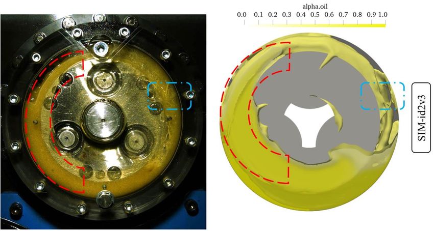
Appl. Sci. 2023, 13, 1014                                                                                              2 of 18

                            Literature Review
                                   The first studies on the no-load power losses arising from the interaction of the
                            moving components with the lubricant in planetary gears date back to Gold et al. [3]. They
                            performed theoretical and experimental studies aimed at studying a two-stage planetary
                            gearbox partially immersed in oil. Further analyses by Kettler [4] concentrated on the
                            operating temperature and the heat balance in dip-lubricated planetary gearboxes. The
                            geometrical parameters of the gearbox such as center distance, planet carrier geometry, and
                            the number of planets, as well as the physical properties of the system such as lubricant
                            parameters and immersion depth, were considered to derive analytical equations for the
                            determination of no-load power losses. Subsequent analyses by Da Costa [5] dealt with
                            the impact of different types of lubricant, namely mineral and synthetic oil, on the no-load
                            power losses for dip lubrication. Studies with injection lubrication were conducted by
                            Höhn et al. [6] and Schudy [1], who built the FZG internal gear test rig to investigate
                            the flank load carrying capacity of internal gears, and the influence of circumferential
                            speeds, material combinations, surface finishing, and lubricants. Suggestions for lubrication
                            conditions, surface finishing, and drive direction were provided. De Gevigney et al. [7]
                            performed an experimental campaign on a planetary gearbox aimed at studying the impact
                            of injection volume rate, lubricant temperature, and rotational speed on efficiency. Recent
                            experiments by Boni et al. [8,9] focused on the detailed analysis of the oil distribution in a
                            dip-lubricated planetary gearbox and its efficiency. They used a front housing made from
                            acryl glass that allowed observation of the oil level and its flow during operation. Various
                            observations were made by considering different rotational speeds, lubricant temperatures,
                            and filling levels. As the planet carrier starts to rotate, the oil tends to distribute around
                            the circumference of the covering box creating a dynamic peripheral oil ring. The authors
                            considered the thickness of the oil ring for the estimation of the churning power losses.
                            This phenomenon has not been observed for other gearbox designs, meaning that it is a
                            peculiar characteristic of planetary gearboxes.
                                   Due to the difficult visibility of internal gearbox components, it is not trivial to have a
                            deep understanding of the lubrication mechanisms, especially for systems characterized
                            by a compact design as planetary gearboxes. However, recent developments in computer
                            science made it possible to use numerical approaches to study the specific problem of
                            interest. In the case of gearbox lubrication, Computational Fluid Dynamics (CFD) can
                            offer substantial benefits in the prediction of the oil flow inside the gearbox. Indeed, in the
                            post-processing phase, it is possible to analyze the oil distribution inside the considered
                            gearbox and to derive information on the lubrication behavior of the system. However, due
                            to the complex kinematics of planetary gearboxes and the high computational resources
                            needed, the numerical studies available in the literature are limited. Moreover, sometimes
                            significant modeling simplifications have been adopted, making it difficult to assess the
                            models’ reliability concerning the oil flow predictions. A recent exhaustive literature review
                            on CFD methods applied to the study of gearbox lubrication and efficiency can be found in
                            Maccioni et al. [10]. In the following, the sole CFD studies relative to epicyclic gearboxes
                            are reported.
                                   Bianchini et al. [11,12] exploited the Multiple Reference Frame (MRF) approach to
                            model a planetary gearbox for aeronautic applications. They increased the gear interspacing,
                            i.e., the meshing region between the sun and the planets, and between the planets and
                            the ring gear, was not modelled. In this way, the squeezing effects could not be simulated
                            and the related axial phenomena occurring in the mating zone were neglected. Moreover,
                            only single-phase simulations were performed. The adopted MRF technique is limited to
                            a regime solution of an unsteady problem without information on the transient behavior.
                            Despite low computational effort, the approach lacks an accurate description of multiphase
                            operating conditions and oil flow phenomena.
                                   More advanced numerical techniques, such as the sliding mesh approach and the
                            dynamic remeshing, are suitable for simulating gear rotation and interaction. FZG test rigs
                            are used for experimental studies on efficiency and lubrication [13]. Concli et al. [14,15]
Appl. Sci. 2023, 13, 1014                                                                                             3 of 18

                            implemented a CFD model of a planetary gearbox studying the no-load power losses for
                            different oil temperatures, immersion depths, and planet carrier rotational speeds. The
                            results were validated with experimental data in terms of power losses. Further studies
                            by Concli et al. [16–18] introduced an innovative remeshing procedure in the opensource
                            CFD code OpenFOAM® [19] for the simulation of the gear meshing. The strategy is based
                            on the computation of extruded numerical grids connected through numerical interfaces
                            to link the non-conformal nodes. When the quality of the mesh decreases, a new mesh
                            is computed for the new gear position. The results are interpolated and the simulation
                            proceeds. The virtual models could predict the efficiency of the system accurately. This
                            algorithm requires the generation of a new mesh whenever bad-quality elements originate.
                            This means that hundreds of meshes may be needed to complete the simulation.
                                  Cho et al. [20] implemented a CFD model based on the overset mesh approach (also
                            called the overlapping grids method, or chimera framework) [21,22] of a planetary gearbox.
                            Filling levels of 30%, 50%, and 70% of the gearbox volume were analyzed. Owing to the
                            numerical analysis, the system design could be optimized and the thermal behavior could
                            be determined. The authors suggest using high filling levels to increase the cooling effects
                            despite the higher churning losses. The commercial software STAR-CCM+ [23] was used.
                                  Liu et al. [2] investigated the oil distribution of the FZG internal gear test rig, which
                            is also the object of this study, for different oil properties and planet carrier speeds in
                            detail. The finite volume-based CFD implementation included a dynamic remeshing
                            approach to describe the rotation and engagement of the gears. They performed multi-
                            phase simulations by applying the Volume of Fluid (VoF) method. The roller bearings of the
                            planet gear shafts were also modeled in the numerical simulation, but their kinematics were
                            described with a pure rotation around the central axis of the planetary gearbox and not with
                            a roto-translation, which resulted in doubling the computational time. They performed
                            a mesh sensitivity analysis with respect to loss torque and oil distribution to obtain an
                            efficient yet accurate modeling approach. The high level of detail of the developed CFD
                            model allowed for the extraction of information on the oil flow inside the gearbox. Liu
                            et al. [2] indicate that with a rather low filling level, it is possible to supply enough oil to
                            the different machine elements. The commercial software ANSYS FLUENT [24] was used.
                            The simulations were parallelized on 80 cores of a high-performing computer cluster.
                                  As it can be noticed from the literature review on planetary gearboxes, the experi-
                            mental studies are limited, and the numerical analyses mostly lack validation, particularly
                            concerning the validation of the oil flow, since the internal part of the gearbox could not be
                            visibly accessed. Moreover, significant computational resources were required to run such
                            simulations. To increase confidence in simulation results, validation by experimental inves-
                            tigations in terms of oil flow is fundamental. Furthermore, efficient remeshing strategies
                            can reduce the computational effort required for finite volume-based CFD simulations. This
                            work fits into these objectives, providing side-by-side comparisons of high-speed camera
                            recordings and CFD results of the oil distribution. The system under consideration is the
                            same investigated by Liu et al. [2]. As a new computationally efficient mesh-handling ap-
                            proach is introduced, the implemented numerical model is ideal to analyze the considered
                            gearbox and can be run on “normal” computers without the need for high-performance
                            computing clusters.

                            2. Materials and Methods
                                 The FZG internal gear test rig is the subject of the investigation and served to validate
                            the simulation results. In the following, a detailed description of the system and the
                            operating conditions is given.

                            2.1. Object of Investigation
                                  The object of investigation is the FZG internal gear test rig presented in Figure 1 (left).
                            The test rig is composed of a planet carrier, three planet gears, and two ring gears, namely, a
                            test ring gear and a drive ring gear. The planet carrier is driven by a continuously variable
The FZG internal gear test rig is the subject of the investigation and served to validate
the simulation results. In the following, a detailed description of the system and the oper-
ating conditions is given.
2.1. Object of Investigation
Appl. Sci. 2023, 13, 1014 4 of 18
The object of investigation is the FZG internal gear test rig presented in Figure 1 (left).
The test rig is composed of a planet carrier, three planet gears, and two ring gears, namely,
a test ring gear and a drive ring gear. The planet carrier is driven by a continuously vari-
electric motormotor
able electric via a shiftable countershaft
via a shiftable transmission.
countershaft The three
transmission. Thestepped planet gears
three stepped of
planet
the test rig are arranged uniformly across the circumference and are engaged
gears of the test rig are arranged uniformly across the circumference and are engaged withwith both the
test
bothring
thegear and the
test ring geardrive
and ring gear. ring
the drive The stages of the
gear. The gearings
stages of theexhibit theexhibit
gearings same gear ratio.
the same
The drive ring gear is float-mounted by spring elements which brace peripheral
gear ratio. The drive ring gear is float-mounted by spring elements which brace peripheral forces.
Axial
forces.forces
Axialare supported
forces by thrust
are supported bywashers mounted
thrust washers in the housing.
mounted in the housing.
Figure1.1. FZG
Figure FZG internal
internal gear
gear test
test rig
rig (left)
(left) and
and rendering
rendering of
of the
the modified
modified FZG
FZG internal
internal gear
gear test
test rig
rig
with transparent housing cover (right) [25].
with transparent housing cover (right) [25].
The FZG
The FZG internal
internal gear
gear test
test rig
rig was
was designed
designed toto operate
operate with
with oil oil injection
injection lubrication.
lubrication.
Thereby, temperature-controlled oil is injected evenly around
Thereby, temperature-controlled oil is injected evenly around the circumference from the circumference from an an
oil supply
oil supply unit
unit via
via two
two separate
separate oiloil distributor
distributor pipes,
pipes, one
one at
at the
the front
front side
side and
and one
one atat the
the
backsideofofthe
backside thetest
testrig.
rig.The
Thetest
test
rigrig
waswas modified
modified to optically
to optically access
access the the internals
internals of theoftest
the
test rig and to realize an oil dip-lubricated operation. Therefore, the
rig and to realize an oil dip-lubricated operation. Therefore, the front facing housing cover front facing housing
cover
was was changed
changed by a modified
by a modified acrylic acrylic
exchange exchange part. Instead
part. Instead of the original
of the original cylindercylinder
roller
roller bearing mounted to the planet carrier, a ball bearing with
bearing mounted to the planet carrier, a ball bearing with compact profile was mounted compact profile was
mounted
to improvetovisibility.
improve The visibility. The front-facing
front-facing distributordistributor pipe was to
pipe was removed removed
furtherto further
improve
improve and
visibility visibility
realizeandanrealize
oil dip an oil dip lubrication.
lubrication. In combination
In combination with aoil
with a throttled throttled
backflow oil
backflow
by by an adjustable
an adjustable valve, a quasi-stationary
valve, a quasi-stationary oil level isoil level is maintained.
maintained. A controlled A controlled
oil sump
oil sump temperature
temperature is achieved is achieved
by a constantby a constant oil circulation
oil circulation and flowand flow heaters.
heaters. Figure 1Figure
(right)1
(right) shows a rendering of the test rig configuration used for the
shows a rendering of the test rig configuration used for the investigations in this study. investigations in this
study.The gear geometry data are reported in Table 1. The mineral oil FVA3A (ISO VG
Thewas
100) [26] gearusedgeometry data areThe
as lubricant. reported in Table
oil sump 1. The mineral
temperature was kept oil FVA3A
constant(ISOat 40VG◦ C.
100)
In
Table 2, the
[26] was physical
used properties
as lubricant. Theofoilthe
sumpoil are reported. was
temperature The camera used for
kept constant at the recordings
40 °C. In Table
is2,athe
Photron
physicalFASTCAM
properties MiniofAX200. A light
the oil are sourceThe
reported. wascamera
exploited
usedto produce high-intensity
for the recordings is a
light
Photrondirected
FASTCAMtowardsMini the front
AX200. cover.
A light source was exploited to produce high-intensity
light directed towards the front cover.
Table 1. Gear geometry.
Unit Ring gear Planet Gear
Center distance (a) mm 59
Normal module (mn ) mm 4.5
Number of teeth (z) - 42 16
Face width (b) mm 16 14
Tip diameter (da ) mm 185.0 82.5
Pressure angle (αn ) ◦ 20
Helix angle (β) ◦ 0
Profile shift coeff. (x) - 0.1817 0.2962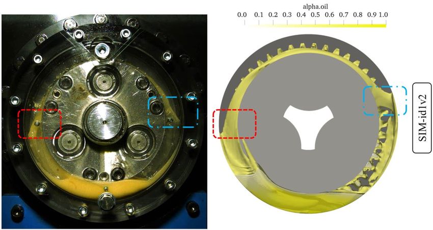
Appl. Sci. 2023, 13, 1014                                                                                                             5 of 18

                            Table 2. Lubricant properties FVA3A.

                                                                                    Unit                              Value
                               Kinematic viscosity (40       ◦ C)                  mm2 /s                               95
                               Kinematic viscosity (100 ◦ C)                       mm2 /s                              10.7
                                    Density (40 ◦ C)                               kg/m3                               864

                            2.2. Operating Conditions
                                  Following Liu et al. [2], planet carrier speeds ranging from 81 rpm to 324 rpm were
                            considered in the experimental and numerical investigations so that the results could be
                            compared with each other. Two oil filling levels were considered: a low one corresponding
                            to 3 times the normal module with respect to the ring gears, as investigated by Liu et al. [2],
                            and a high one corresponding to the centerline level (as a typical operating condition of
                            planetary gearboxes, which was previously investigated numerically by Cho et al. [20]
                            and experimentally by Boni et al. [8]). In Table 3, the analyzed operating conditions
                            are summarized.

                            Table 3. Operating conditions.

                              Simulation        Lubricant             Planet Carrier          Planet Gears         Tangential Speed at
                                Name           Filling Level         Speed nt in rpm       Speed np,abs in rpm     Pitch Circle vt in m/s
                               SIM-id1v1                                     81                    132                        0.8
                               SIM-id1v2            3 · mn                  162                    263                        1.6
                               SIM-id1v3                                    324                    526                        3.2
                               SIM-id2v1                                     81                    132                        0.8
                               SIM-id2v2         centerline                 162                    263                        1.6
                               SIM-id2v3                                    324                    526                        3.2
                            “SIM” stands for simulation, “id” for immersion depth, and “v” for velocity. As already mentioned, two immersion
                            depths and three rotational velocities were analyzed. Therefore, “id” has values of 1 and 2, while “v” has values
                            of 1, 2, and 3.

                            2.3. Mathematical Description and Governing Equations
                                 The CFD code used to perform the simulations is based on OpenFOAM® v7 [19],
                            a Finite Volume Method (FVM) [27] software. The complexity of the two-phase oil–air
                            splash lubrication in the planetary gearbox was modelled with the Volume of Fluid (VOF)
                            model [28]. The sum of the two fluids volume ratios (αoil and αair ) in each control volume
                            is equal to 1:
                                                                   αoil + α air = 1                                  (1)
                                 When αoil = 1, the control unit is full of oil; when αoil = 0, the control unit is filled
                            with air; when 0 < αoil < 1, an oil–air interface is contained in the control unit. The solution
                            of the continuity equation of the volume fraction allows to trace the oil–air interface.

                                                                             ∂α
                                                                                + ∇( αu) = 0                                             (2)
                                                                             ∂t
                                 The Multidimensional Universal Limiter with Explicit Solution (MULES) [29] algo-
                            rithm was used to achieve a better boundedness of the volume fraction field. This is
                            achieved by adding a dummy velocity field (uc ) acting perpendicular to the interface to the
                            conservation equation of the α field:

                                                                    ∂α
                                                                       + ∇(αu) + ∇( uc α(1 − α)) = 0                                     (3)
                                                                    ∂t
                                  The generic property φ (as viscosity and density) of the equivalent fluid is calculated as:

                                                                      φeq = αoil φoil + (1 − αoil ) φair                                 (4)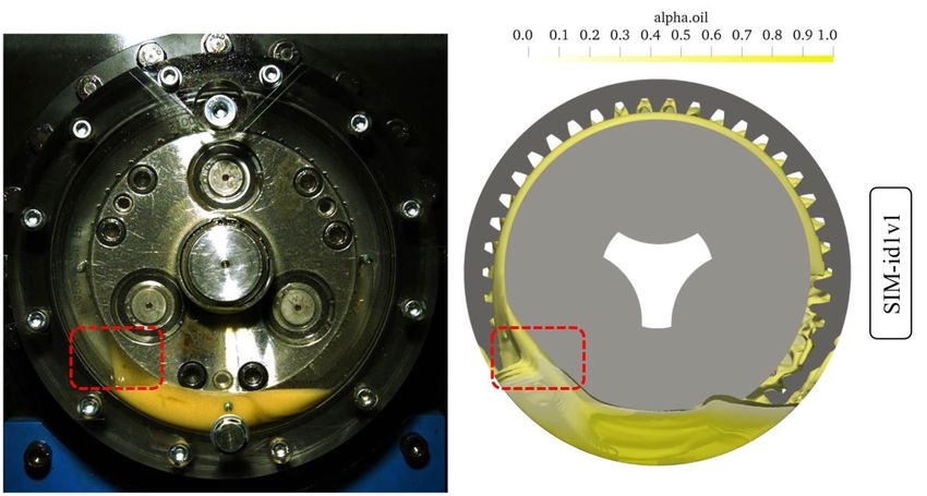
Appl. Sci. 2023, 13, 1014                                                                                                 6 of 18

                                  The fluid-dynamic problem requires solving of the continuity and the momentum
                              equations for the oil–air mixture:

                                                                      ∂ρ
                                                                         + ∇(ρu) = 0                                          (5)
                                                                      ∂t
                                               ∂(ρu)                              h              i
                                                      + ∇(ρuu) = −∇ p + ∇ µ ∇u + ∇uT + ρg + F                                 (6)
                                                 ∂t
                              where ρ is the density, u is the fluid velocity, µ is the viscosity, g is the gravity acceleration,
                              and F represents the vector of external forces. The weighted average properties are used
                              so that the two conservation equations are associated with the continuity equation of the
                              volume fraction.

                              2.4. CFD Modeling of the Oil Flow
                                    In this section, the implementation of the CFD model in OpenFOAM® is discussed. A
                              detailed description of the meshing procedure and of an innovative mesh-handling strategy
                              for low computational effort is explained.

                              2.4.1. Geometrical Considerations
                                   The CFD model was derived starting from the CAD model by considering the areas
                              where the lubricant can be present. Therefore, different from the structural analysis, the
                              negative model of the solid parts was considered. Small-scale features such as screws,
                              springs, and seals were neglected as they are not expected to have a noteworthy impact on
                              the oil distribution. Further cleaning of the geometry included the removal of chamfers,
                              edges, and small clearances. The final geometry consists of two ring gears, three planets,
                              and the planet carrier. To avoid numerical singularities in the gear meshing region, the
                              ring gears were scaled to 102% of their nominal size (in the radial direction only). This
                              preliminary action is required for all finite volume-based simulations of intersecting objects
                              and is not expected to significantly influence the main oil flow in the gearbox.

                              2.4.2. Meshing Approach
                                        As the investigated planetary gearbox is composed of spur gears, it is possible to
                                   exploit an extruded mesh approach. Extruded meshes are preferable over tetrahedral
                                   meshes, since they exhibit higher quality, lower memory usage, and faster calculation
                                   times. In a first step, the domain was decomposed in three subdomains which were
                                   meshed separately. The introduction of AMIs (Arbitrary Mesh Interfaces) [30] enabled
                                   the connection of adjacent non-conformal mesh domains. In this way, AMIs ensure the
Appl. Sci. 2023, 13, x FOR PEER REVIEW
                                   continuity of the field variables across the mesh discontinuities. In Figure 2, the 7three
                                                                                                                         of 18

                                   subdomains and the assembled domain are shown.

                              Figure2.2.Domain
                              Figure     Domaindecomposition:
                                                decomposition:thethe
                                                                   AMIs enable
                                                                     AMIs      the the
                                                                          enable   numerical connection
                                                                                       numerical        among
                                                                                                 connection   the 3 subdomains.
                                                                                                            among   the 3 subdo-
                              mains.

                                   The first and the third subdomains are composed of the external parts of the gearbox
                               and include a portion of the housing, the planet carrier, and the planet shafts. Their ge-
                               ometry is relatively simple, and an extruded mesh can be obtained. On the other side, the
                               second subdomain contains the planets, the ring gears, and the remaining parts of the
Appl. Sci. 2023, 13, 1014 Figure 2. Domain decomposition: the AMIs enable the numerical connection among the 3 subdo-
7 of 18
mains.
The first and the third subdomains are composed of the external parts of the gearbox
The first and the third subdomains are composed of the external parts of the gearbox
and include a portion of the housing, the planet carrier, and the planet shafts. Their ge-
and include a portion of the housing, the planet carrier, and the planet shafts. Their
ometry
geometry is relatively
is relativelysimple, andand
simple, an extruded mesh
an extruded cancan
mesh be obtained. On the
be obtained. On other side,side,
the other the
second subdomain contains the planets, the ring gears, and the remaining
the second subdomain contains the planets, the ring gears, and the remaining parts of the parts of the
housing
housing and
and of of the
the planet
planet carrier.
carrier. The
The geometry
geometry ofof this
this subdomain
subdomain is is much
much more
more complex
complex
and, to generate a swept mesh, it is necessary to create axial partitions in
and, to generate a swept mesh, it is necessary to create axial partitions in correspondencecorrespondence
with eachtooth
with each toothflank.
flank.Additional
Additionalpartitions
partitions with
with thethe shape
shape of the
of the planets,
planets, the the
ringring gears,
gears, and
and the planet carrier profiles were created. Once all the necessary partitions
the planet carrier profiles were created. Once all the necessary partitions were implemented, were imple-
mented, an extruded
an extruded mesh was mesh was obtained
obtained for thesubdomain.
for the second second subdomain.
In FigureIn3,Figure 3, the lon-
the longitudinal
gitudinal and the cross views of the assembled
and the cross views of the assembled mesh are reported. mesh are reported.
Figure 3. Longitudinal and cross views of the assembled mesh. A full extruded mesh is obtained.
The final
The final mesh
mesh is
is composed
composed of of about
about 0.65
0.65 M
M prismatic
prismatic elements.
elements. AA grid
grid sensitivity
sensitivity
analysis of the CFD model was performed. The element number was varied
analysis of the CFD model was performed. The element number was varied from 0.37 from 0.37 M
M
to 0.78 M. The maximum deviation of the power loss was only about 4%, even
to 0.78 M. The maximum deviation of the power loss was only about 4%, even if the oil if the oil
flow could
flow could be
be resolved
resolved better
better with
with increasing
increasing the
the element
element number.
number. The
The grid
grid with
with 0.65
0.65 M
M
elements was
elements was chosen
chosen asas aa good
good compromise between oil
compromise between oil flow
flow resolution
resolution and
and computing
computing
time. The element size in the computational domain was of 1 mm. The analysis
time. The element size in the computational domain was of 1 mm. The analysis performed performed
by Liu et al. [2] on the same system was composed of about 0.73 M tetrahedral elements,
by Liu et al. [2] on the same system was composed of about 0.73 M tetrahedral elements,
thus resulting in a comparable number of elements, but in a different cell type. The quality
thus resulting in a comparable number of elements, but in a different cell type. The quality
parameters of the initial and the displaced mesh at the end of the imposed motion are listed
parameters of the initial and the displaced mesh at the end of the imposed motion are
in Table 4. As can be seen, the max non-orthogonality (angle between the line connecting
two cell centers and the normal of their common face) was kept below 70 and the maximum
skewness (distance between the intersection of the line connecting two cell centers with
their common face and the center of that face) was kept below 4. The geometry and the
mesh computation phase was handled via Python [31] scripts and Salome [32].
Table 4. Quality parameters of the mesh.
Max Non-Orthogonality [◦ ] Max. Skewness [-]
Initial mesh Displaced mesh Initial mesh Displaced mesh
50.7 66.1 1.6 2.8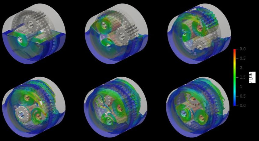
Appl. Sci. 2023, 13, 1014                                                                                             8 of 18

                            2.4.3. Mesh-Handling Approach
                                 The simulation of the considered gearbox requires the introduction of a dynamic mesh
                            approach. Indeed, the boundary motion causes the deformation of the mesh, which needs
                            to be replaced with a new valid one after every few simulated angular positions. The
                            Local Remeshing Approach (LRA), available in some commercial software, can handle
                            the boundary motion with deformable elements that stretch every timestep. The distorted
                            elements that arise from the boundary node motion are automatically reconstructed by
                            the code based on the imposed quality parameters. Despite its effectiveness, this method
                            requires a sufficiently low timestep to ensure a stable remeshing process. This is mainly
                            because each local remeshing iteration can lead to elements having a smaller size with
                            respect to the original ones. Thus, the lower computational efficiency is related to an
                            increase in the number of elements and the consequent decrease in the allowable timestep
                            to keep the simulation stable. In the current work, an innovative remeshing approach was
                            implemented, namely, an adapted version of the Global Remeshing Approach with Mesh
                            Clustering (GRAMC ), which was already used by the authors to study spur, helical, and
                            bevel gear pairs [33]. The main idea behind the GRAMC is that it is possible to compute
                            a mesh set that covers one engagement and reuse it recursively during the simulation.
                            In this way, the computational effort associated with the remeshing process is drastically
                            reduced since the grids in the predefined wheel positions are immediately available for the
                            mesh-to-mesh interpolation of the results. Moreover, this approach allows the user to have
                            a direct control over the mesh size. This allows to keep the cell number almost constant
                            throughout the simulation, thus avoiding the creation of extremely small elements that
                            would impact on the allowable timestep needed to keep the maximum Courant number
                            below 1.
                                 As the system under investigation is a planetary gearbox, the kinematics involves not
                            only the pure rotation of the planet carrier, but also the roto-translation of the planets. This
                            means that the GRAMC cannot be applied directly. However, after the first engagement
                            between the planets and the ring gear has occurred, it is possible to reuse the first mesh by
                            applying to it a rigid rotation of an angle θ given by:

                                                                            2π
                                                                      θ=                                                 (7)
                                                                           zring

                                  By exploiting this artifice, the enormous advantages of the GRAMC on the computa-
                            tional time can still be exploited, and the set of mesh that covers one complete planet–ring
                            gear engagement can be used for the entire simulation. From the mesh deformation tests,
                            it emerged that a set of 10 grids is sufficient to complete one engagement. Therefore,
                            every 10 meshes a rigid rotation of multiples of θ was applied to the initial mesh set, thus
                            providing the necessary meshes for the whole simulation. The rigid rotation of the mesh
                            is a simple operation that requires less than one second on a modern hardware, while the
                            remeshing of the computational domain for every position would be much more compu-
                            tationally expensive. In Figure 4 the workflow of the adopted mesh-handling strategy
                            is illustrated.
                                  As it can be noticed, the procedure foresees the mesh-to-mesh interpolation of the
                            results. With each successive domain being conformal, the mapping is perfectly consistent.
                            Furthermore, the mesh set is composed of very similar grids in terms of element size and
                            count, hence the interpolation errors are minimized. The whole simulation process is
                            automated in a Bash [34] script. The base case can be adapted to investigate the desired
                            operating conditions by changing the velocity and the time libraries consistently.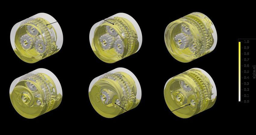
Appl.Sci.
Appl. Sci.2023,
2023,13,
13,1014
x FOR PEER REVIEW 99 of
of 18
18
Figure 4. Flowchart of the implemented mesh-handling strategy.
As it can be noticed, the procedure foresees the mesh-to-mesh interpolation of the
results. With each successive domain being conformal, the mapping is perfectly con-
sistent. Furthermore, the mesh set is composed of very similar grids in terms of element
size and count, hence the interpolation errors are minimized. The whole simulation pro-
cess is automated in a Bash [34] script. The base case can be adapted to investigate the
desired
Figure operating
Figure4.4. Flowchartconditions
Flowchart of
ofthe by changing
theimplemented
implemented the velocity
mesh-handling
mesh-handling and the time libraries consistently.
strategy.
strategy.
2.4.4. Boundary
2.4.4. Boundary
As Conditions
Conditions
it can be andprocedure
and
noticed, the Numericalforesees
Numerical Settingsthe mesh-to-mesh interpolation of the
Settings
Themain
The
results. mainkinematic
With kinematic
each characteristic
characteristic
successive of
domainofbeing a planetary
a planetary gearbox
gearbox
conformal, theand and is that
is that
mapping the planets
theperfectly
is planets per-
con-
perform
form a a roto-translation
roto-translation around around
the the
centercenter
axis. axis.
This This
means means
that the that the
velocity
sistent. Furthermore, the mesh set is composed of very similar grids in terms of element velocity
of the of the
planets
planets
issize
zeroand is zero
at the at
pitch
count, the pitch
pointthe
hence with point with the
the ring gear,
interpolation ring gear,
and are
errors and
it increases it
minimized. increases
linearly
Thein linearly
the radial
whole in the radial
direction.
simulation pro-
direction.
The
cessvelocityThe velocity
contour
is automated acontour
inplot plot
that [34]
Bash thatthe
describes
script. describes
The base the
casekinematics
kinematics iscan
shown inisFigure
be adaptedshownto5.in Figure 5. the
investigate
desired operating conditions by changing the velocity and the time libraries consistently.
2.4.4. Boundary Conditions and Numerical Settings
The main kinematic characteristic of a planetary gearbox and is that the planets per-
form a roto-translation around the center axis. This means that the velocity of the planets
is zero at the pitch point with the ring gear, and it increases linearly in the radial direction.
The velocity contour plot that describes the kinematics is shown in Figure 5.
Figure5.
Figure Velocity contour
5.Velocity contour plot
plot of
of the
the system
system in
in the
the central
central partition.
partition.
AA dedicated
dedicated boundary
boundary condition
condition that
that applies
applies the
the roto-translation
roto-translation waswas implemented
implemented
and assigned to the three planets. The planet carrier is assigned a boundary
and assigned to the three planets. The planet carrier is assigned a boundary condition that condition that
applies a pure rotation around its center axis. The housing and the ring
applies a pure rotation around its center axis. The housing and the ring gears are fixed in gears are fixed in
space and do not undergo any deformation. With it being a closed system, the pressure and
space and do not undergo any deformation. With it being a closed system, the pressure
the volumetric fraction fields have a Neumann boundary condition, i.e., must be calculated.
and the volumetric fraction fields have a Neumann boundary condition, i.e., must be cal-
Wall adhesion models can be included by specifying the contact angle parameter (angle
culated.
Figure 5.Wall adhesion
Velocity contourmodels
plot of can be included
the system by specifying
in the central partition.the contact angle parameter
formed by a liquid at the three-phase boundary where liquid, gas, and solid intersect).
(angle formed by a liquid at the three-phase boundary where liquid, gas, and solid
Factors such as porosities, surface roughness, and impurities can affect this parameter
A dedicated
influencing boundary
the wettability ofcondition that applies
the wall surfaces. In thethecurrent
roto-translation was implemented
work, the contact angle was
and assigned to the three planets. The planet carrier is assigned
not considered, and the Neumann boundary condition (zeroGradient) was applied a boundary condition to that
the
applies a pure rotation
alpha field on the walls. around its center axis. The housing and the ring gears are fixed in
space and do not undergo any deformation. With it being a closed
The PIMPLE (merged PISO-SIMPLE) algorithm was used since it exploits the possibil- system, the pressure
and
ity tothe
usevolumetric
relatively highfraction
timefields
steps have a Neumann
with relaxation boundary
(SIMPLE) andcondition, i.e.,the
to maintain must be cal-
temporal
culated. Wall
information adhesion
(PISO). Themodels
time stepcanwas set to 0.1◦byrotation
be included specifying theplanet
of the contact angle In
carrier. parameter
Table 5,
(angle
the formedsettings
numerical by a liquid
used inatthethesimulation
three-phaseare boundary
summarized. where liquid, gas, and solid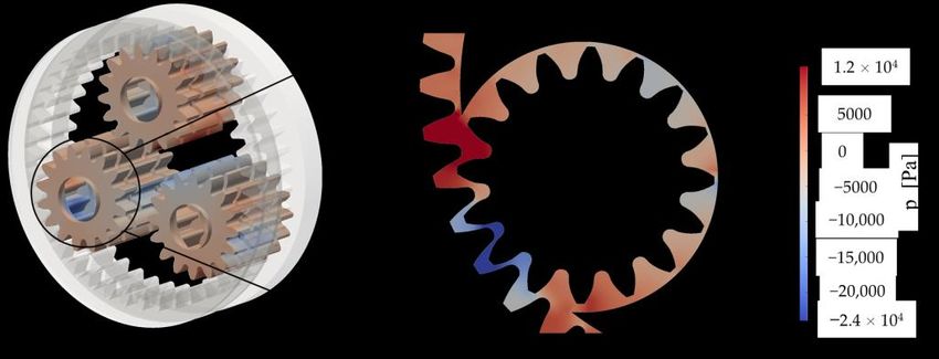
Appl. Sci. 2023, 13, 1014                                                                                             10 of 18

                            Table 5. Numerical settings used in the simulations.

                                        Convergence criterion                                    1 × 10⁻⁵
                                      Maximum Courant number                                         1
                                           Pressure solver                       PCG (preconditioned conjugate gradient)
                                                                               PBiCG (stabilized preconditioned bi-conjugate
                                             Velocity solver
                                                                                                 gradient)
                                     Time derivative discretization                 First order implicit Euler scheme
                                        Velocity discretization                    Second order linear-upwind scheme
                                  Convection of the volumetric fraction               Second order van Leer scheme

                            2.4.5. Computational Performance
                                 A 48 GFLOPs Linux Workstation (INTEL Xeon® Gold 6154 CPU, 4 Cores, 3 GHz) was
                            used to run the simulations, which required on average 20 h each for a single planet carrier
                            rotation. The low computation time achieved by parallelizing the computations on only
                            4 cores can be attributed to the newly implemented remeshing procedure, which is based
                            on the recursive use of the initial mesh. This way, the effort of the remeshing process is
                            drastically reduced.
                                 Without the mesh-handling strategy explained in Section 2.4.3 (computation of a
                            limited mesh set and application of rigid rotations), the computational domain would
                            have needed to be partitioned and meshed continuously for every gear position, with a
                            significant increase in the computational effort. In Table 6, the implemented GRAMC with
                            a multi-rotation strategy is compared with a general approach that does not consider the
                            repeatability of the tooth positions.

                            Table 6. Comparison of the computational effort between a standard and the newly implemented
                            remeshing algorithm.

                                                                            GRAMC        General Approach       Net Gain %
                             Simulation time for the analyzed gearbox
                                                                              20 h              400 h              95%
                                     (1 planet carrier rotation)

                                 By the developed procedure, a 95% time gain per planet carrier rotation could be
                            achieved. This is mainly because the grids were previously computed and are immediately
                            available for the mapping process as the simulation continues. Moreover, owing to the
                            proper domain partitioning that was carried out in the pre-processing phase, it was possible
                            to mesh the geometry with a series of extrusions starting from a 2D mesh. The resulting
                            3D elements are triangular prisms, which exhibit higher quality parameters and require
                            less memory consumption with respect to tetrahedrons, thus resulting in faster calculation
                            times. Liu et al. [2] simulated the same planetary gearbox with a local remeshing approach.
                            Their simulation model, which also considered the roller bearings and a high level of
                            detail, implemented in ANSYS Fluent, required 15–20 h parallelized on 80 cores of a
                            high-performance computing cluster.

                            3. Results and Discussion
                                 In this chapter, the results of the simulations and the high-speed camera recordings
                            of the experimental investigations for the selected operating points are shown. Firstly, a
                            direct comparison with the data coming from high-speed camera recordings is presented.
                            Secondly, the views taken from different perspectives were extracted from the CFD models
                            to describe the oil flow inside the planetary gearbox.

                            3.1. Comparison of Numerical and Experimental Results
                                 Exemplary simulation results with respect to the oil flow were compared with high-
                            speed camera recordings to validate the oil distribution in the front part of the gearbox.
                            The simulation results are shown after one rotation of the planet carrier, as no appreciable
els to describe the oil flow inside the planetary gearbox.
els to describe the oil flow inside the planetary gearbox.
3.1. Comparison of Numerical and Experimental Results
3.1. Comparison of Numerical and Experimental Results
Exemplary simulation results with respect to the oil flow were compared with high-
speed Exemplary simulationtoresults
camera recordings with
validate therespect to the oil flow
oil distribution in thewere
frontcompared with
part of the high-
gearbox.
Appl. Sci. 2023, 13, 1014 speed camera recordings to validate the oil distribution in the front part of
The simulation results are shown after one rotation of the planet carrier, as no appreciable the gearbox.
11 of 18
The simulation results are shown after one rotation of the planet carrier,
changes in the oil flow were observed moving on with the simulation. Figures 6–8 show as no appreciable
changes in the comparison
a side-by-side oil flow werefor observed
the low moving on with
filling level the simulation.
operating conditions. Figures
Dashed 6–8colored
show
arectangles
side-by-side
changes in the comparison
are oil
usedflow werefor the low
observed
to highlight and filling level
moving
emphasize on operating
with conditions.
the simulation.
similarities between Dashed
theFigures 6–8colored
experimental show
and
rectangles
anumerical are
side-by-side used to highlight and emphasize similarities between the experimental
comparison for the low filling level operating conditions. Dashed colored
results. and
numericalare
rectangles results.
used to highlight and emphasize similarities between the experimental and
numerical results.
Figure 6. Experimental (left) and CFD (right) comparison of the oil flow for SIM-id1v1.
Figure6.6.Experimental
Figure Experimental(left)
(left)and
andCFD
CFD(right)
(right)comparison
comparisonof
ofthe
theoil
oilflow
flowfor
forSIM-id1v1.
SIM-id1v1.
Appl. Sci. 2023, 13, x FOR PEER REVIEW 12 of 18
Figure7.7.Experimental
Figure Experimental(left)
(left)and
andCFD
CFD(right)
(right)comparison
comparisonofofthe
theoil
oilflow
flowfor
forSIM-id1v2.
SIM-id1v2.
Figure 7. Experimental (left) and CFD (right) comparison of the oil flow for SIM-id1v2.
Figure8.
Figure 8. Experimental
Experimental (left)
(left)and
andCFD
CFD(right)
(right)comparison
comparisonofof
thethe
oiloil
flow forfor
flow SIM-id1v3.
SIM-id1v3.
For the SIM-id1v1 operating condition (Figure 6), the low rotational speed translates
into a low amount of oil being dragged by the planet carrier rotation. This results in the
formation of an oil track in the lower left region (red dashed rectangle) and only a small
quantity is carried up by the planet carrier rotation. This behavior is well captured by theAppl. Sci. 2023, 13, 1014 12 of 18
For the SIM-id1v1 operating condition (Figure 6), the low rotational speed translates
into a low amount of oil being dragged by the planet carrier rotation. This results in the
formation of an oil track in the lower left region (red dashed rectangle) and only a small
quantity is carried up by the planet carrier rotation. This behavior is well captured by the
simulation. As the velocity increases (SIM-id1v2, Figure 7), more oil is dragged by the
planet carrier. This reflects into higher splashing on the left area (red dashed rectangle),
as well as into a pronounced oil ejection on the right side of the gearbox (blue dashed dot
rectangle). Both phenomena are very well predicted by the CFD model. At the highest
velocity (SIM-id1v3, Figure 8), the centrifugal forces promote a marked radial expansion of
the oil towards the housing, also including the region above the planet carrier (red dashed
arc). However, the simulation predicts a greater amount of oil in the upper region. A
possible explanation for this difference could be related to the modeling of wall adhesion at
the contact point between the wall surface and the interface, as explained in Section 2.4.4.
These three operating conditions were investigated by Liu et al. [2] as well. Moreover, in
their model, the planet carrier rotation drags the oil from the sump and brings it to the
upper part of the system. It was observed that the higher the rotational speed, the higher
the amount of oil being splashed around. The fact that their model includes the bearings can
introduce some differences in the small-scale flows in that region. Dedicated sub-models
with a much finer mesh around the bearings and specific boundary conditions for the
correct description of the rings’ and rollers’ kinematics would be necessary to accurately
Appl. Sci.
Appl. Sci. 2023,
2023, 13,
13, xx FOR
FOR PEER
PEER REVIEW
REVIEW 13 of
of 18
18
predict the oil flow and the velocity and pressure gradients in the bearings 13 region [35].
Figures 9–11 show a side-by-side comparison for the high filling level operating conditions.
Figure 9. Experimental (left) and CFD (right) comparison of the oil flow for SIM-id2v1.
Figure 9. Experimental (left) and CFD (right) comparison of the oil flow for SIM-id2v1.
Figure 10. Experimental (left) and CFD (right) comparison of the oil flow for SIM-id2v2.
Figure 10. Experimental (left) and CFD (right) comparison of the oil flow for SIM-id2v2.
Figure 10. Experimental (left) and CFD (right) comparison of the oil flow for SIM-id2v2.Appl. Sci. 2023, 13, 1014 13 of 18
Figure 10. Experimental (left) and CFD (right) comparison of the oil flow for SIM-id2v2.
Figure11.
Figure 11.Experimental
Experimental(left)
(left)and
andCFD
CFD(right)
(right)comparison
comparisonof
ofthe
theoil
oilflow
flowfor
forSIM-id2v3.
SIM-id2v3.
For the SIM-id2v1 operating condition (Figure 9), from the high-speed camera record-
ings it can be observed that a peculiar shape of the oil originates: these are Taylor–Couette
flows [36] that arise between the rotating planet carrier and the fixed internal surfaces of the
housing, as demonstrated by De Gevigney et al. [7]. The wave that can be seen in front of
the planet carrier is well predicted by the CFD model (red dashed rectangle). As the velocity
increases (SIM-id2v2, Figure 10), the wave shape of the oil tends to cover a larger area in
the gearbox (red dashed arc). A slight decrease in the oil sump level could be observed
on the right side of the planet carrier (blue dashed dot rectangle). At the highest velocity
(SIM-id2v3, Figure 11), similarly to SIMI-id1-v3, the centrifugal forces create an evident oil
ring around the planet carrier (red dashed arc), in accordance with the observations by Boni
et al. [8]. The oil is splashed all around the gearbox (blue dashed dot rectangle), resulting in
a completely different behavior with respect to the other investigated velocities, in which
the oil is also present in the front region. The absence of the oil in front of the planet carrier
and its splashing around the gearbox is well predicted by the model. However, differently
from the experimental recordings, in the CFD model of SIM-id2v1 and SIM-id2v2 more oil
is sticking to the planet carrier and less oil is falling into the sump. A possible explanation
for this difference could be related to the modeling of wall adhesion at the contact point
between the wall surface and the interface, as explained in Section 2.4.4. For SIM-id2v3, a
larger amount of oil in the red dashed arc is predicted by the simulation if compared with
the experimental recordings, but the shape and the flow path of the oil have been captured.
In this section, the numerical results were compared with the experiments. The
transparent housing allowed to observe the flow that originates in the front part of the
gearbox. In this regard, the oil rings that originate from the planet carrier rotation are
already evident from the shown side-by-side comparison. Additional oil rings originate
inside the gearbox around the planets, as will be presented from the CFD results in the
following paragraph.
3.2. Details of the Oil Flow in the Planetary Gearbox
To gain deeper insight into the oil flow inside the gearbox, 3D isometric views are
reported for the analyzed operating conditions. The gearbox housing was made transparent
to enable access to the internal fluid domain region. In Figure 12, the oil distribution is
shown for the analyzed operating conditions. In the top and in the bottom row of the
figure, the low and the high filling level cases are shown, respectively. Near each result, the
corresponding operating condition is indicated in a box on the bottom right.3.2. Details of the Oil Flow in the Planetary Gearbox
To gain deeper insight into the oil flow inside the gearbox, 3D isometric views are
reported for the analyzed operating conditions. The gearbox housing was made transpar-
ent to enable access to the internal fluid domain region. In Figure 12, the oil distribution
is shown for the analyzed operating conditions. In the top and in the bottom row of the
Appl. Sci. 2023, 13, 1014 14 of 18
figure, the low and the high filling level cases are shown, respectively. Near each result,
the corresponding operating condition is indicated in a box on the bottom right.
Figure 12. Oil distribution inside the gearbox for the analyzed operating conditions. Top row: low
filling level cases. Bottom row: high filling level cases. Axial flows (squeezing effect) and oil rings
around the planets are highlighted.
For the low filling level cases (top row), the oil is dragged from the sump and delivered
to the other parts of the gearbox. As the rotational velocity increases, more oil participates to
the lubrication and the ring gears receive a greater amount of oil. For the high filling levels
(bottom row), oil rings also originate around the planet gears, as illustrated in Figure 12.
These are generated by the roto-translation of the planets which are completely submerged
when they are below the centerline of the gearbox. As they move above the centerline, the
oil remains entrapped between the planets and the planet carrier, and the roto-translation
of the wheels promotes the formation of these additional oil rings. The faces of the gears
remain wet, and the cylindrical shape of the gear shafts contribute to the rotatory movement
of the oil around the wheels.
The squeezing effect that can be seen in all cases derives from the mutual interaction
between the planets and the ring gears. The squeezing of the oil from the planet–ring gear
meshing zone was also observed by Boni et al. [8]. The CFD simulations provide a physical
explanation for these axial fluxes. Indeed, while the gears engage, the gap between the
teeth reduces and increases continuously during the gear mesh. The sudden contraction
of this volume implies an overpressure in the gap that gives origin to axial fluxes. After
reaching the minimum value for the volume, the volume of the gap suddenly increases
again causing a lower pressure in the gap (it should be considered that the pressure drop
is significantly smaller than environment pressure of 1 bar, and, therefore, this pressure
gradient will not lead to phase exchanges, namely, cavitation). It should be highlighted
that the calculation of the pressure gradients due to the volume variation during the gear
meshing with the present model is not representative of the pressures on the mating flanks
near the contact area. These considerations are confirmed in literature [37–41]. In Figure 13,
the pressure contour in the mating region that justifies the oil squeezing is reported. The
2D representation shows the slice taken in the center of the middle gear.
In Figure 14, the evolution of the oil flow at different timesteps during the planet
carrier rotation is illustrated for SIM-id2v3. From the standstill position (A), the planets
gradually enter in contact with the oil in the sump (B, C, D). The oil is then distributed
circumferentially along the ring gears (E, F). At this velocity, the planet carrier rotation
discards the oil radially towards the housing. The oil that remains in the sump is recovered
by the wheel’s passage during the motion and is continuously brought to the other parts of
the gearbox.is significantly smaller than environment pressure of 1 bar, and, therefore, this pressure
gradient will not lead to phase exchanges, namely, cavitation). It should be highlighted
that the calculation of the pressure gradients due to the volume variation during the gear
meshing with the present model is not representative of the pressures on the mating flanks
near the contact area. These considerations are confirmed in literature [37–41]. In Figure
Appl. Sci. 2023, 13, 1014 15 of 18
13, the pressure contour in the mating region that justifies the oil squeezing is reported.
The 2D representation shows the slice taken in the center of the middle gear.
Appl. Sci. 2023, 13, x FOR PEER REVIEW 16 of 18
13. Pressure contour
Figure 13. contour on
on the
the wheels.
wheels.
In Figure 14, the evolution of the oil flow at different timesteps during the planet
carrier rotation is illustrated for SIM-id2v3. From the standstill position (A), the planets
gradually enter in contact with the oil in the sump (B, C, D). The oil is then distributed
circumferentially along the ring gears (E, F). At this velocity, the planet carrier rotation
discards the oil radially towards the housing. The oil that remains in the sump is recov-
ered by the wheel’s passage during the motion and is continuously brought to the other
parts of the gearbox.
Figure
Figure 14.14.(A–F)
(A–F)evolution
evolution of the oil flow
of the for thefor
oil flow SIM-id2v3 operating
the SIM-id2v3 conditioncondition
operating at different
at timesteps
different
timesteps
during the during the planet
planet carrier carrier
rotation. Therotation. The oil is
oil is gradually gradually
brought brought
to the to theofother
other parts parts ofThe
the gearbox. the
gearbox.between
contact The contact between
the planets andthethe
planets and the
ring gears ringtogears
seems seems
be well to be well
lubricated. Thelubricated. The rota-
rotatory motion of
toryoil
the motion of theorigin
flow gives oil flow gives
to oil origin
rings to oil
around rings
the around
planet theand
carrier planet carrier and the planets.
the planets.
In this section,
In section,aabetter
betterinsight
insightinto
intothethe
lubrication
lubricationin the planetary
in the gearbox
planetary was was
gearbox pro-
vided. TheThe
provided. oil oil
squeezed
squeezedbetween
between the planets
the planetsand
andthe
thering
ringgears
gearscreates
creates axial
axial flows that
meet the
meet the oil
oil coming
coming from
from the
the planet
planet carrier
carrier rotation,
rotation, confirming
confirming whatwhat was
was observed
observed by
Boni et
Boni et al.
al. [8].
[8]. Additional
Additional oil
oil rings
rings around
around the the planets
planets were
were detected.
detected. The
The reason
reason behind
behind
these
these fluxes
fluxes could
could bebe explained
explained byby the
the layout
layout and
and kinematics
kinematics of of planetary
planetary gearboxes,
gearboxes, in
in
which rotation and revolution motions
which rotation and revolution motions coexist. coexist.
4.
4. Conclusions
Conclusions
In
In the
thepresent
presentwork,
work,a planetary
a planetarygearbox was was
gearbox analyzed with awith
analyzed combined experimental–
a combined experi-
numerical
mental–numerical approach. A transparent housing cover allowed recordingflow
approach. A transparent housing cover allowed recording of the oil in the
of the oil
front
flow in the front part of the gearbox by a high-speed camera. This allowed to captureflow
part of the gearbox by a high-speed camera. This allowed to capture the oil the
characteristics that typically
oil flow characteristics that originate
typically in planetary
originate in gearboxes. The currentThe
planetary gearboxes. analysis proposes
current analy-
asisnew remeshing approach that is on the one hand based on the proper partitioning
proposes a new remeshing approach that is on the one hand based on the proper par- of
the computational
titioning domain to obtain
of the computational domain antoextruded
obtain anmesh and, mesh
extruded on theand,
other
onhand, based
the other on
hand,
an innovative mesh-handling strategy that exploits a pre-computed set of
based on an innovative mesh-handling strategy that exploits a pre-computed set of mesh mesh for the
whole simulation. The implemented approach allowed running of such simulations on
for the whole simulation. The implemented approach allowed running of such simula-
only four cores without the need for a computer cluster. The simulation results are in good
tions on only four cores without the need for a computer cluster. The simulation results
agreement with the experimental observations, despite some discrepancies at the centerline
are in good agreement with the experimental observations, despite some discrepancies at
immersion depth, where the oil remained stitched on the planet carrier in the simulations
the centerline immersion depth, where the oil remained stitched on the planet carrier in
and did not flow down. The simulations at lower immersion depth could be compared
the simulations and did not flow down. The simulations at lower immersion depth could
be compared with Liu et al. [2]. The oil flow prediction in the front part of the gearbox is
similar to the one predicted in their work. However, a different level of detail can intro-
duce some differences in the oil flow.
The current work allowed a good understanding of the oil flow characteristics in theYou can also read