Over 30% efficiency bifacial 4 terminal perovskite heterojunction silicon tandem solar cells with spectral albedo
←
→
Page content transcription
If your browser does not render page correctly, please read the page content below
www.nature.com/scientificreports
OPEN Over 30% efficiency
bifacial 4‑terminal
perovskite‑heterojunction silicon
tandem solar cells with spectral
albedo
Sangho Kim1,2, Thanh Thuy Trinh3,4, Jinjoo Park5, Duy Phong Pham6,7, Sunhwa Lee8,
Huy Binh Do9, Nam Nguyen Dang10,11, Vinh‑Ai Dao10,11*, Joondong Kim1,12* & Junsin Yi13*
We developed and designed a bifacial four-terminal perovskite (PVK)/crystalline silicon (c-Si)
heterojunction (HJ) tandem solar cell configuration albedo reflection in which the c-Si HJ bottom sub-
cell absorbs the solar spectrum from both the front and rear sides (reflected light from the background
such as green grass, white sand, red brick, roofing shingle, snow, etc.). Using the albedo reflection
and the subsequent short-circuit current density, the conversion efficiency of the PVK-filtered c-Si HJ
bottom sub-cell was improved regardless of the PVK top sub-cell properties. This approach achieved
a conversion efficiency exceeding 30%, which is higher than those of both the top and bottom
sub-cells. Notably, this efficiency is also greater than the Schockley–Quiesser limit of the c-Si solar
cell (approximately 29.43%). The proposed approach has the potential to lower industrial solar cell
production costs in the near future.
The highest recorded efficiency of a practical single-junction silicon solar cell is 26.7%, obtained under an inter-
digitated back contact (IBC) silicon heterojunction (HJ) configuration. The cell was developed by Kaneka in
Japan1. However, this recorded efficiency remains lower than the theoretical efficiency limit of a single-junction
silicon solar cell (i.e., 29.43%)2. The discrepancy between the practical and theoretical efficiencies can be attrib-
uted to thermalization and transmission loss3–5. To overcome this drawback, tandem solar cells consisting of
multijunction configurations with various optical band gaps to harvest the entire solar spectrum range were
developed following extensive i nvestigations3. Both inorganic-inorganic and organic–inorganic materials have
been examined to create tandem a rchitectures6–13.
Tandem configurations can be roughly grouped into three categories, namely spectral splitting, four-terminal
(mechanically stacked), and two-terminal (monolithically integrated)14,15. Among these, the optical splitting
architecture showed an efficiency of approximately 28%16. However, the device configuration is complicated
1
Photoelectric and Energy Device Application Lab. (PEDAL), Multidisciplinary Core Institute for Future Energies
(MCIFE), Incheon National University, Incheon 22012, Republic of Korea. 2Department of Energy Science,
Sungkyunkwan Univeristy, 2066 Seobu‑ru, Suwon‑si, Gyeonggy‑do 16419, Republic of Korea. 3Department
of Physics, International University, Block 6. Linh Trung Ward, Thu Duc District, Ho Chi Minh City 720400,
Vietnam. 4Vietnam National University, Ho Chi Minh City, Vietnam. 5Division of Energy and Optical
Technology Convergence, Major of Energy Convergence Engineering, Cheongju University, 298, Daeseong‑ro,
Chungcheongbuk‑do, Cheongwon‑gu, Cheongju‑si 28503, Korea. 6Division of Computational Physics, Institute
for Computational Science, Ton Duc Thang University, Ho Chi Minh City, Vietnam. 7Faculty of Electrical and
Electronics Engineering, Ton Duc Thang University, Ho Chi Minh City, Vietnam. 8Departement of Electrical
and Computer Engineering, Sungkyunkwan University (SKKU), Seoul 16419, Republic of Korea. 9Ho Chi Minh
City University of Technology and Education, 01 Vo Van Ngan, Thu Duc District, Ho Chi Minh City 700000,
Vietnam. 10Future Materials and Devices Lab. (FM&D), Institute of Fundamental and Applied Sciences, Duy Tan
University, Ho Chi Minh City 700000, Vietnam. 11Faculty of Electrical‑Electronic Engineering, Duy Tan University,
Da Nang 550000, Vietnam. 12Department of Electrical Engineering, Incheon National University, Incheon 22012,
Republic of Korea. 13College of Information and Communication Engineering, Sungkyunkwan University (SKKU),
Suwon 16419, Republic of Korea. *email: daovinhai@duytan.edu.vn; joonkim@incheon.ac.kr; junsin@skku.edu
Scientific Reports | (2021) 11:15524 | https://doi.org/10.1038/s41598-021-94848-4 1
Vol.:(0123456789)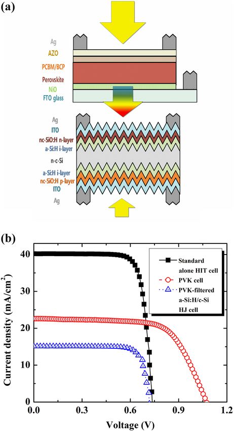
www.nature.com/scientificreports/
such that the device cannot be feasibly produced in bulk. In a monolithically integrated configuration, top and
bottom sub-cells are electrically coupled in series; hence, the short-circuit current density ( Jsc) of the tandem
device is limited by J sc of the lowest sub-cell. Thus, the tandem power conversion efficiency (PCE) is c onstrained7.
This implies that current matching between the top and bottom sub-cells must be strictly fulfilled and form the
initial challenge concerning the fabrication of two-terminal tandem solar c ells10. Another challenge concerns the
high-quality deposition of the top sub-cell on the textured surface of the bottom silicon sub-cell16.
Alternatively, in the four-terminal tandem architecture, the top and bottom sub-cells are optically—but not
electrically—coupled. The requirement for perfect current matching is thus negligible. The top and bottom sub-
cells are independently fabricated; therefore, the high quality of the top sub-cell can be easily recreated on a glass
substrate due to its smooth surface8. Some effort has been expended to create the four-terminal configuration in
tandem devices. Quiros et al. optimized single-junction perovskite (PVK) solar cells via nanostructure transpar-
ent electrodes using a silver nanowire. The obtained efficiency was 26.7% and 25.2% for perovskite-passivated
emitter rear locally diffused (PERL) and perovskite-IBC tandem devices, r espectively17. Using the same device
configuration, Wang et al. reported a conversion efficiency of 27.0% based on a perovskite-heterojunction with
an intrinsic thin-layer (HIT) configuration. This was achieved by employing a M oO3/Au/MoO3 multilayer for
a transparent electrode of the perovskite top sub-cell14. A similar architecture employing C 60 for the electrode
selective contact and a S nOx/ZTO/ITO transparent electrode for the Perovskite top sub-cell was created using
a perovskite-silicon tunnel oxide passivated contact (TOPCon) tandem configuration (with a PCE of 26.7%)18.
Another attempt to achieve the same device configuration involved copper indium gallium selenide (CIGS)
instead of crystalline silicon (c-Si) based material for the bottom sub-cell. The obtained conversion efficiency
of ~ 5.9% was lower than that of the perovskite-Si-based HJ tandem solar c ells8. By employing a charge trans-
fer–induced 2,9-dimehtyl-4,7-diphenyl-1,10-phenanthroline (BCP):Ag complex between a C 60 electron-transport
layer and sputtered indium-zinc oxide top electrode to reduce sputtering damage for underlayer, the efficiency
of the semi-transparent perovskite solar cells (PSCs) was improved from 16.14 to 18.19%. An efficiency of
27.59% was then obtained for the four-terminal PSCs/TOPCon c onfiguration19. The four-terminal with bifacial
PSCs–metal wrap through silicon hetero-junction configuration was also reported; using this configuration, a
device conversion efficiency of 30.5% was r eached20.
Prior studies indicate that the standard-alone Si-based HJ solar cell always exhibits high efficiency (> 20%)
in defiance of the cell structure. Nevertheless, the PCE of the PVK-filtered Si-based HJ bottom sub-cell showed
an efficiency of less than 10%. This occurred because a short wavelength range was yielded by the perovskite top
sub-cell, following which the Jsc of the bottom sub-cell, and, accordingly, the PCE were reduced. Studies have
attempted to improve Jsc of the bottom sub-cell via minimized absorption using the perovskite sub-cell, which
can be accomplished using high-band-gap perovskite material or highly transparent electrodes. Therefore, to
achieve higher efficiency in tandem solar cells, the top and bottom sub-cells must fulfill solar spectra with respect
to their optical band gaps. To meet this requirement, a bifacial four-terminal perovskite-HIT tandem solar cell
with spectral Albedo was investigated in this study for the first time. This design configuration is advantageous
thought its ability to improve Jsc of the bottom sub-cell via spectral albedo, in defiance of the top sub-cell proper-
ties and without raising costs compared with mono-facial tandem cells.
Results and discussion
Evaluating top sub‑cell candidates for the bifacial four‑terminal tandem solar cell. The preced-
ing discussion suggests that the PCEs of individual sub-cells must be as high as possible, without presenting sub-
cell current density matching, to obtain the highest PCE of the bifacial four-terminal tandem device. Recently,
organic and inorganic materials, such as hydrogenated amorphous silicon (a-Si:H), hydrogenated amorphous
silicon germanium (a-SiGe:H), hydrogenated microcrystalline silicon (μc-Si:H), and P VK3,6–10,12–18, have been
employed for the top sub-cell. To classify the appropriate top sub-cell candidates for tandem device application,
different single-junction thin film solar cells were fabricated and characterized. Figure 1 presents the quantum
efficiencies (QEs) for different types of top sub-cell candidates. QE curves can be roughly divided into two zones,
namely, the short-wavelength region (< 600 nm) and long-wavelength region (> 600 nm). The QE behavior of
the a-Si:H and a-SiGe:H thin-film solar cells (TFSs) shows negligible differences in the wavelength range of 300
to ~ 550 nm, whereas that of a-SiGe:H TFS shows an improvement in the wavelength range of ~ 550 to ~ 800 nm
when compared to the a-Si:H TFS. Such an improvement can be attributed to the improved light absorption in
the long-wavelength range for the case of a-SiGe:H with a low optical band gap, as reported previously3. Figure 1
also exhibits the QE behavior of the μc-Si:H TFS. The result thereof confirmed the enhanced infrared absorption
of the μc-Si:H TFS compared with the amorphous silicon TFS. It is interesting to note that the perovskite top
sub-cell’s QE indicates a significant enhancement in the all-wavelength zone of interest compared with semi-
transparent amorphous silicon TFS. The semitransparent perovskite sub-cell, on the other hand, shows substan-
tial improvement in the wavelength range of 300 nm to ~ 800 nm. However, the cut-off of the perovskite’s QE
occurs at a wavelength of 800 nm, whereas that of the μc-Si:H TFS is still available up to 1100 nm.
Base on the experimental QE results, the integrated photocurrents were simulated and are presented in
Table 1. The calculated results may be predicted. The highest integrated photocurrent is 26.76 mA/cm2 for the
μc-Si:H solar cell, followed by that for the semitransparent perovskite (22.60 mA/cm2), a-SiGe:H (18.50 mA/
cm2), and a-Si:H (15.65 mA/cm2) TFS. Therefore, the semitransparent μc-Si TSF and perovskite TSF are poten-
tial candidates for achieving high conversion efficiency in the top sub-cell of a four-terminal tandem device.
In addition, the characteristics of the different semitransparent cells were examined and are presented in Fig. 2
and Table 1. These results are similar to those of the QEs. The μc-Si TSF has the highest J sc of 26.81 mA/cm2,
followed by perovskite TFS (Jsc of 22.66 mA/cm2), a-SiGe:H TFS ( Jsc of 18.32 mA/cm2), and a-Si:H TFS ( Jsc of
15.56 mA/cm2). However, the behavior of Voc was found to be different than that of Jsc. The highest Voc was
Scientific Reports | (2021) 11:15524 | https://doi.org/10.1038/s41598-021-94848-4 2
Vol:.(1234567890)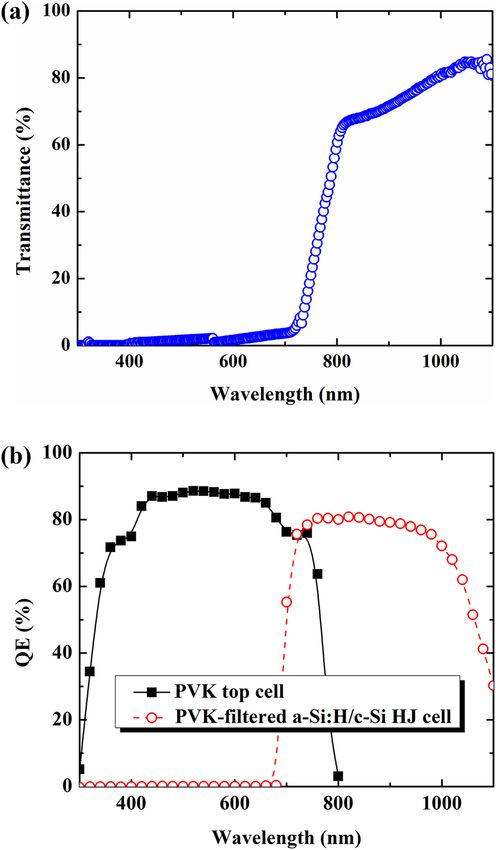
www.nature.com/scientificreports/
Figure 1. Measured QE spectra of the various top sub-cell candidates. The black, red, blue, and magenta lines
depict the QE of the PVK, a-Si:H, a-SiGe:H, and μc-Si:H thin film solar cell, respectively.
Jsc (mA cm2)
Cal. Meas. Voc (V) FF (%) Efficiency (%)
PVK 22.60 22.66 1.10 68.60 17.10
a-Si:H 15.65 15.56 0.90 70.40 9.86
a-SiGe:H 18.50 18.32 0.85 64.20 10.00
μc-Si:H 26.76 26.81 0.51 68.22 9.33
Table 1. Calculated Jsc and performance metrics of various top sub-cell candidates.
Figure 2. Illuminated current–voltage characteristics of the various top sub-cell candidates and standard-alone
a-Si:H/c-Si heterojunction solar cell under 1 sun. The black, red, blue, magenta, and olive lines indicate the J-V
curves for the PVK, a-Si:H, a-SiGe:H, μc-Si:H thin film solar cell and c-Si HJ solar cell, respectively.
obtained for the perovskite TFS (1100 mV), followed by a-Si:H TFS (900 mV), a-SiGe:H TFS (850 mV), and μc-Si
TFS (510 mV). Finally, the PCE gathers all the characterizations of the device performance. This information
is also presented in Table 1. Here, all amorphous silicon and microcrystalline silicon exhibited a PCE of ~ 10%.
Notably, the semitransparent perovskite solar cell had a PCE of up to 17.1%. Thus, our analysis indicates that the
fabricated semitransparent perovskite thin-film solar cell is potentially the top candidate for the top sub-cell in a
four-terminal tandem solar cell, in defiance of the highest J sc from the μc-Si:H thin-film solar cell.
Scientific Reports | (2021) 11:15524 | https://doi.org/10.1038/s41598-021-94848-4 3
Vol.:(0123456789)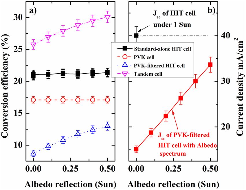
www.nature.com/scientificreports/
Figure 3. (a) Schematic of the bifacial 4-terminal PVK/c-Si HJ tandem solar cell with albedo reflection. (b)
Illuminated current–voltage curves under 1 sun of the standard-alone c-Si HJ solar cell (black color), PVK
filtered c-Si HJ solar cell (blue color) and the PVK solar cell (red color).
Bifacial four‑terminal tandem solar cell fabrication and characterizations. The four-terminal
tandem solar cell structure was constructed, as shown in Fig. 3a. The semitransparent perovskite serves as the
top sub-cell, that is, a solar filter for the a-Si:H/c-Si bottom sub-cell. Figure 3b shows the performance of the bifa-
cial four-terminal tandem device under 1 sun illumination on the front side. The characteristics of the standard-
alone a-Si:H/c-Si HJ solar cell without a PVK filter were measured and are presented in Fig. 3b. The obtained
results indicate that the performance of the PVK remains unchanged. By contrast, several characteristics of
the PVK-filtered a-Si:H/c-Si HJ solar cell showed a significant decrease, particularly J sc (from ~ 40.00 mA/cm2
to ~ 15.15 mA/cm2). Hence, the conversion efficiency decreased significantly, from 23.35 to 8.68%.
To elucidate the main reason for J sc reduction of the PVK-filtered HIT sub-cell, the transmittance of the PVK
cell was investigated, as depicted in Fig. 4a. The PVK cells absorbed all solar spectra in the short-wavelength
range. This implies that the solar spectrum that reaches the bottom sub-cell is lower than that without PVK fil-
tering, leading to decreased electron–hole pair generation, which can be detrimental to Voc and particularly Jsc.
The result of a low J sc for a PVK-filtered HIT bottom sub-cell can be clearly understood upon analyzing the QE
results. Figure 4b shows the QE of a PVK sub-cell and PVK-filtered HIT sub-cell. Based on the QE results, the
calculated photocurrents are 21.50 and 16.22 mA/cm2 for the PVK top sub-cell and PVK-filtered HIT bottom
sub-cell, respectively. These values are consistent with the experimental results. A conversion efficiency (sum
of the conversion efficiencies of the PVK cell and the PVK-filtered cell) of 25.78%, which is higher than that of
each independent sub-cell, was achieved for the four-terminal perovskite-HIT configuration.
Thus, the a-Si:H/c-Si HJ bottom sub-cell performance remained significantly below that under the standard
operation condition (AM 1.5 G or 1 Sun) (Jsc of ~ 15.15 mA/cm2 of the PVK-filtered HIT cell is significantly below
Scientific Reports | (2021) 11:15524 | https://doi.org/10.1038/s41598-021-94848-4 4
Vol:.(1234567890)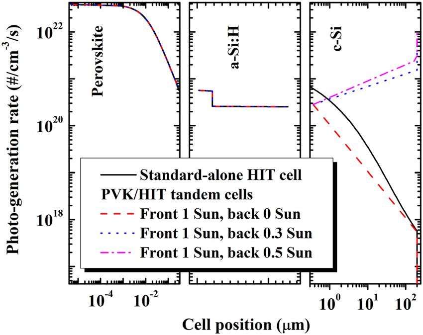
www.nature.com/scientificreports/
Figure 4. (a) Transmittance through perovskite top sub-cell solar cell. (b) Quantum efficiency of the PVK top
sub-cell and of the PVK-filtered c-Si HJ solar cell.
the state-of-the-art value of the standard-alone HIT cell with a Jsc of ~ 40 mA/cm2), owing to the PVK-filter on the
top, as seen in Fig. 4b. To push the PVK-filtered a-Si:H/c-Si HJ bottom sub-cell works close to 1 sun condition or
the state-of-the-art, causing a rise in the Jsc and conversion efficiency, the bifacial 4-terminal tandem design with
spectral albedo was also promoted (Fig. 3a). Here, the albedo reflection intensity can be accurately adjusted in
the range of 0–0.5 sun by altering the distance between the cell holder and illumination source, as seen in Fig. 5.
A calibrator was used to accurately control the albedo reflection. The advantage of using the bifacial solar cell
is its acquisition of the solar spectrum from both sides: direct solar spectrum from the front side and reflected
solar spectrum from the background (green grass, white sand, red brick, roofing shingle, snow, etc.)6. Figure 6a
shows the efficiencies of the bifacial standard-alone a-Si:H/c-Si HJ and the bifacial four-terminal perovskite/c-Si
HJ tandem solar cell as a function of the albedo spectrum. Here, the front illumination was kept fixed at 1 sun.
The conversion efficiency of the top PVK cell (red circle) remains nearly unchanged, whereas that of the bifacial
standard-alone HIT cell (black square) showed slight improvement with the albedo reflection. The conversion
efficiency of the PVK-filtered HIT bottom sub-cell (blue triangle) showed a significant enhancement from 8.68
to 12.99% when the spectral albedo increased from 0 to 0.5 sun (refer to the supporting information for details
in Fig. S1, S2). Consequently, the conversion efficiency (sum of the efficiencies of the PVK and PVK-filtered HIT
cells) of the bifacial four-terminal tandem cell (pink triangle) showed a significant improvement from 25.78 to
30.09%, apparent in Fig. 7 and Table 2. To date, this remains a comparatively high conversion efficiency value
achieved in PVK/HIT tandem solar cells.
The current density of the PVK-filtered HIT sub-cell as a function of the albedo spectrum was measured, as
seen in Fig. 6b. The Jsc of the standard-alone HIT cell (black square) under 1 sun is also presented for reference.
As shown in Figs. 6b, 7 and Table 2, we observe a monotonous increase in the J sc of the PVK-filtered HIT cell
(red square, Fig. 6b) from ~ 15.15 mA/cm2 to ~ 33.64 mA/cm2 (Fig. 7 and Table 2) and in the albedo reflection
from 0 sun to 0.5 sun. It is worth noting that the highest Jsc with an albedo reflection of 0.5 sun is still lower than
that of the standard J sc value of the HIT cell (~ 40 mA/cm2). It is suggested that a higher J sc regarding the upper
Scientific Reports | (2021) 11:15524 | https://doi.org/10.1038/s41598-021-94848-4 5
Vol.:(0123456789)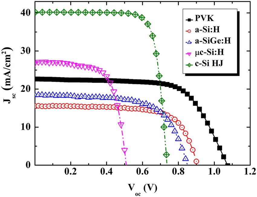
www.nature.com/scientificreports/
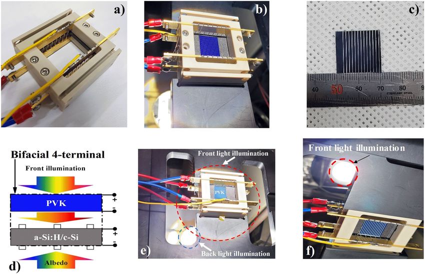
Figure 5. (a) A photo image of a solar cell Zig for bifacial 4-terminal tandem solar cell measurement. (b)
The solar cell Zig with an a-Si:H/c-Si HJ solar cell. (c) A real image of the semitransparent PVK solar cell. (d)
A configuration of the front and albedo light source; the distance between the cell’s holder and the albedo
light source can be adjusted. (e) The solar cell Zig with PVK/c-Si HJ tandem solar cell and bi-directional light
irradiation turned on. (f) The real image from back-side view of the bifacial 4-terminal PVK/c-Si HJ tandem
solar cell with light source turned on.
Figure 6. (a) The conversion efficiency of the PVK top sub-cell (red color), standard-alone c-Si HJ solar
cell (black color), PVK-filtered c-Si HJ solar cell (blue color), and a bifacial 4-terminal PVK/c-Si HJ tandem
solar cell (pink color) as a function of albedo reflection. (b) Jsc of the standard-alone c-Si HJ solar cell under 1
sun (black color) and the Jsc of the PVK-filtered c-Si HJ solar cell bottom sub-cell as a function of the albedo
spectrum (red color).
limits of the c-Si HJ solar cell of approximately 42 mA/cm2 can be achieved using albedo reflection for the bifacial
four-terminal tandem cell. To achieve higher conversion efficiency, further investigations such as lesser plasma
damage of underlying organic–inorganic l ayers21 or higher albedo light intensity are required.
Bifacial 4‑terminal PVK/HIT tandem solar cell modeling. Simulated results were employed to exam-
ine the PVK/c-Si HJ tandem solar cell to elucidate the reason for the improvement in Jsc and, thereby, the con-
Scientific Reports | (2021) 11:15524 | https://doi.org/10.1038/s41598-021-94848-4 6
Vol:.(1234567890)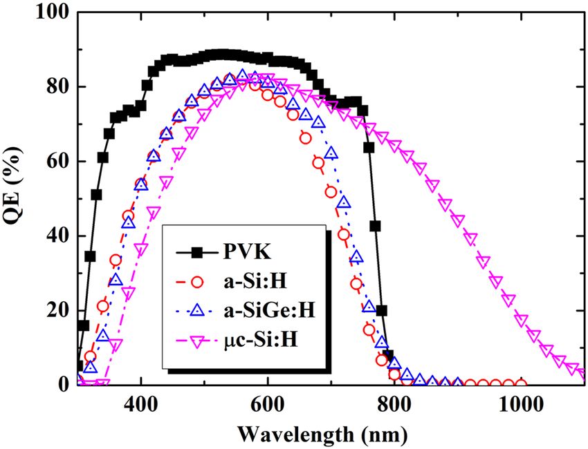
www.nature.com/scientificreports/

                                  Figure 7.  Representative J–V curves of the PVK top sub-cell and PVK-filtered a-Si:H/c-Si HJ bottom sub-cell
                                  in a bifacial 4-terminal PVK/c-Si HJ tandem solar cell under 1.0 sun (front-side) and 0.5 sun (back-side).

                                                                                                                                  The
                                                                                                                                  normalized
                                                                                                                                  conversion
                                   Solar cell                               Voc (V)          Jsc (mA/cm2)        FF (%)           efficiency (%)
                                   PVK cell                                 1.100            22.66               68.60            17.10
                                   PVK-filtered a-Si:H/c-Si HJ cell         0.728            33.64               79.52            12.99
                                   Tandem solar cell                        –                –                   –                30.09

                                  Table 2.  Summary of photovoltaic parameters for semitransparent PVK, a-Si:H/c-Si HJ solar cell under 1.0
                                  sun (front) and 0.5 sun (back) and for the summed 4-terminal bifacial PVK/c-Si tandem device.

                                  Figure 8.  Plots of the photo-generated rate in a bifacial 4-terminal PVK/c-Si HJ tandem solar cell, with
                                  variation in the albedo spectrum, as a function of the cell position; here, the red, blue, and pink lines indicate
                                  albedo reflection at 0, 0.3, and 0.5 sun, respectively. The photo-generated rate of the standard c-Si HJ solar cell,
                                  as a function of the cell position, was also represented for reference (black line).

                                  version efficiency. Figure 8 shows the simulated photo-generated rate distribution, which was determined using
                                  AFORS-HET software, within the PVK/c-Si HJ tandem solar cell under three selected conditions: without spec-
                                  tra albedo (dashed red line), with spectra albedo of 0.3 sun (dotted blue line) and with spectra albedo of 0.5
                                  sun (dash-dotted magenta line). For reference purposes, the simulated photo-generated rate distribution inside
                                  the a-Si:H/c-Si HJ solar cell without a PVK filter (solid black line) is plotted as a function of the cell position.
                                  We observed that the bottom sub-cell of the PVK/HIT tandem solar cell without albedo reflection shows fewer

Scientific Reports |   (2021) 11:15524 |                    https://doi.org/10.1038/s41598-021-94848-4                                                   7

                                                                                                                                                   Vol.:(0123456789)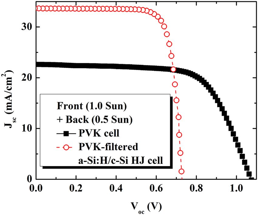
www.nature.com/scientificreports/
photo-generated electron–hole pairs in the entire device length than the standard-alone a-Si:H/c-Si heterojunc-
tion solar cell, a matter which deems detrimental to all parameters of the bottom sub-cell, as discussed earlier.
For PVK/c-Si HJ tandem solar cells, the photo-generated rate was kept unchanged through the PVK and emit-
ter region (a-Si:H) of the bottom sub-cell, as opposed to the albedo reflection conditions. As a results, the albedo
reflection did not contribute to the performance of the PVK cell, where we notice no change in the PCE of the
PVK with variation in the albedo spectrum intensities. Using the albedo spectrum, the generated electron–hole
pairs were improved remarkably along the bottom sub-cell position, particularly those close to the end of the
cell. The higher the albedo reflection is, the higher the photo-generated rate will be.
In summary, a bifacial four-terminal PVK/c-Si HJ tandem solar cell with albedo reflection was proposed in
this study. In a traditional four-terminal PVK/c-Si HJ configuration, the solar spectrum in the short-wavelength
region is absorbed by the PVK top sub-cell, leaving the remaining spectrum to be absorbed by the c-Si HJ bottom
sub-cell. However, not all photons corresponding to bottom sub-cell’s optical bandgap can be yielded. The Jsc
(~ 15.15 mA/cm2) and consequent the conversion efficiency (8.68%) values for the bottom sub-cell are, there-
fore, far below the state-of-the-art values of the standard cell. Our approach employed a bifacial four-terminal
PVK/c-Si HJ tandem structure with an albedo reflection, which increases the number of absorbed photons
into the a-Si:H/c-Si HJ bottom sub-cell. As a result, J sc and the conversion efficiency of the c-Si HJ bottom sub-
cell improved from ~ 15.15 to 33.5 mA/cm2 and from 8.68 to 12.99%, respectively, when the albedo reflection
increased from 0 to 0.5 sun. The excellent photon yielding of the a-Si:H/c-Si HJ sub-cell enabled a high J sc. We
showed that the conversion efficiency of the PVK/HIT tandem solar cell was as high as 30.10%. These findings
encourage further studies on the improvement of the conversion efficiency of four-terminal tandem solar cell
using albedo reflection and/or low plasma damage of underlying organic–inorganic l ayers21.
Methods
For the PVK solar cell fabrication, methylammonium-lead (ΙΙ) iodide (CH3NH3PbI3) was employed as the absor-
bent layer, which was positioned between a NiO layer and phenyl C 61-butyric acid methyl ester (PCBM) material.
The NiO and PCBM layers served as hole and electron transport materials, respectively. The final structure of the
PVK solar cell is, thus, glass/fluorine-doped tin oxide (FTO)/NiO/absorber/PCBM/BCP/aluminum-doped zinc
oxide (AZO)/Ag. FTO glasses were treated in ultrasonic bath with acetone, ethanol, and DI water, for 10 min each
in sequences. An atomic layer deposition (ALD) system was employed to deposit the NiO hole transport layer
at a temperature of 200 °C. Stoichiometric MAPbI3 solution was prepared by mixing DMF and DMSO solvents
to prepare the perovskite precursor solution. The precursor solution, after being stirred overnight in an inert
atmosphere glove box, was dropped on the NiO layer in accordance with the spin coating method, after which
the layer was dried on a hot plate to form the perovskite absorber layer. The PCMB/BCP electron transport layer
was then coated on the absorber layer according to the spin coating technique; AZO was grown at 100 °C by
using the ALD system. Finally, the Ag electrode was developed using thermal evaporation with a shadow mask.
The detailed fabrication process can be found in a previous publication by Seo et al.22.
For an a-Si:H/c-Si HJ solar cell fabrication, commercial Czochralski-grown n-type c-Si wafers 200 μm thick
with an electrical resistivity of ~ 2.7 Ω·cm were used as the absorbent layer. Henceforth, the a-Si:H/c-Si HJ solar
cell is termed the HJ solar cell. Passivated a-Si:H(i) layers were first deposited on both sides of the wafers. The
nc-SiO:H(p) layer was then deposited on top of the a-Si:H(i) at one side as hole collector, whereas nc-SiO:H(n)
layer was deposited on top of the a-Si:H(i) on the other side as the electron collector.
All a-Si:H layers were grown via plasma-enhanced chemical vapor deposition in a cluster system. For a bifacial
configuration, 80 ± 5-nm-thick ITO was coated using a magnetron sputtered on top of the nc-SiO:H(p) and nc-
SiO:H(n) layers in sequence. Finally, Ag finger grids were printed on top of the ITO layers via a low-temperature
screen-printing method. The details of the growth conditions employed for all layers can be found in a previous
report23. The final structure of the HJ solar cell is as follows: Ag(finger-grids)/ITO/nc-SiO:H(n)/a-Si:H(i)/c-
Si(n)/a-Si:H(i)/nc-SiO:H(p)/ITO/Ag(finger grids).
To measure the current density–voltage characteristic of the bifacial four-terminal tandem solar cell, the
bifacial solar cell Zig was designed for bi-directional investigation, as illustrated in Fig. 5a. Real photographs of
a bifacial solar cell Zig with an a-Si:H/c-Si HJ solar cell are shown in Fig. 5b. Real photographs of semitranspar-
ent PVK solar cell and measurement schematics are shown in Fig. 5c,d, respectively. An actual photo images
of the PVK/c-Si HJ tandem solar cell with bi-directional light irradiation are shown in Fig. 5e. Finally, a view
from back-side of an actual photographs of the PVK/c-Si HJ solar cell with bi-directional light irradiation are
shown in Fig. 5f. Here, we used two xenon lamps for the bi-directional investigation of PVK/c-Si HJ tandem
solar cell characteristics. The light intensity of the first Xenon lamp (front side) was kept unchanged at 1 sun (a
light intensity of 100 mW/cm2), whereas the light intensity of the Xenon lamp at the back side (spectral albedo)
was adjusted from 0.0 to 0.5 sun by changing the distance between the back-side’s cell and the light source. For
accurate controls of the light intensity, a calibrated reference cell (Newport, 91150-KG) was used. It is noted
that in all measured setups, the temperature was maintained at 25 °C. The conversion efficiency of the bifacial
four-terminal configuration cell can be determined by adding the conversion efficiency of the PVK cell and the
PVK-filtered a-Si:H/c-Si HJ bottom sub-cell as follows:
ηBifacial−4T = ηPVK−Top + ηPVK−filtered c−Si HJ bottom,alb (1)
Here the conversion efficiency of the PVK-filtered c-Si HJ bottom sub-cell, ηPVK fileted c-Si HJ bottom, alb, is the
normalized conversion efficiency (output power normalized to 1 sun illumination, that is, for 100 mW/cm2)6.
The optical transmittance of the PVK cells was characterized using an ultraviolet–visible spectrophotometer
in the wavelength range of 300–1100 nm (Sinco S-3100). The QE of each sub-cell was determined at 25 °C
using a solar cell spectrum response/QE/incident photo-to-current efficiency measurement system G1218a (PV
Scientific Reports | (2021) 11:15524 | https://doi.org/10.1038/s41598-021-94848-4 8
Vol:.(1234567890)www.nature.com/scientificreports/
Measurements, Inc., Boulder, Co, USA). Automat FOR the Simulation of HETerostructure software (AFORS-
HET 3.0.1) was utilized to characterize the photo-generation rate within the PVK-HJ tandem solar c ells24.
Received: 22 March 2021; Accepted: 15 July 2021
References
1. Kunta, Y. et al. Silicon heterojunctin solar cell with interdigitated back contacts for a photoconversion efficiency over 26%. Nat.
Energy. 2, 1–8 (2017).
2. Shockley, W. & Queisser, H. J. Detailed balance limit of efficiency of pn junction solar cells. J. Appl. Phys. 32, 510–519 (1961).
3. Park, J. et al. High efficiency inorganic/inorganic amorphous silicon/heterojunction silicon tandem solar cells. Sci. Rep. 8, 15382
(2018).
4. Gilot, J., Wienk, M. M. & Janssen, R. A. J. Optimizing polymer tandem solar cells. Adv. Mater. 22, 67–71 (2010).
5. Kim, T. et al. Triple-junction hybrid tandem solar cells with amorphous silicon and polymer-fullerene blends. Sci. Rep. 8, 7154
(2015).
6. Thomas, C. R. R., Rebecca, S., Andre, A., Stuart, G. B. & Harry, A. A. The influence of spectral albedo on bifacial solar cells: a
theoretical and experimental study. Appl. Phys. Lett. 106, 243902 (2015).
7. Sameshima, T. et al. Multi junction solar cells stacked with transparent and conductive adhesive. Jpn. J. Appl. Phys. 50, 052301
(2011).
8. Bailie, C. D. et al. Semi-transparent perovskite solar cells for tandems with silicon and CIGS. Energy Environ. Sci. 8, 956–963 (2015).
9. Mailoa, J. P. et al. A 2-terminal perovskite/silicon multijunction solar cell enabled by a silicon tunnel junction. Appl. Phys. Lett.
106, 121105 (2015).
10. Lee, Y., Dao, V. A., Iftiquar, S. M., Kim, S. & Yi, J. Current transport studies of amorphous n/p junctions and its application in
A-Si:H/HIT-type tandem cells. Prog. Photovolt. Res. Appl. 24, 52–58 (2016).
11. Schade, H. & Smith, Z. E. Optical properties and quantum efficiency of A-Si1−xCx:H/a-Si: H solar cells. J. Appl. Phys. 57, 568–574
(1985).
12. Albrecht, S. et al. Monolithic perovskite/silicon-heterojunction tandem solar cells processed at low temperature. Energy Environ.
Sci. 9, 81–88 (2016).
13. Kim, S. et al. The recorded open-circuit voltage and fill factor achievement of A-Si: H p-i-n/HIT-type tandem solar cells by tuning
up the crystalline in tunneling recombination junction layer. Semicond. Sci. Technol. 34, 065004 (2019).
14. Wang, Z. et al. 27%-Efficiency four-terminal perovskite/silicon tandem solar cells by sandwiched gold nanomesh. Adv. Funct.
Mater. 30, 1908298 (2019).
15. Werner, J. et al. Efficient NIR-transparent perovskite solar cells enabling direct comparison of 4-terminal and monolithic perovskite/
silicon tandem cell. ACS Energy Lett. B 1(2), 474–480 (2016).
16. Uzu, H. et al. High efficiency solar cells combining a perovskite and a silicon heterojunction solar cells via an optical splitting
system. Appl. Phys. Lett. 106, 013506 (2015).
17. Quiroz, C. O. R. et al. Balancing electrical and optical losses for efficient 4-terminal Si–perovskite solar cells with solution processed
percolation electrodes. J. Mater Chem. A. 6, 3583–3592 (2018).
18. Rohatgi, A. et al. 26.7% Efficient 4-terminal perovskite-silicon tandem solar cell composed of a high-performance semitransparent
perovskite cell and a doped poly-Si/SiOx passivating contact silicon cell. IEEE J. Photovolt. 10, 417–422 (2020).
19. Ying, Z., Yang, Y., Zheng, J., Zhu, Y., Xiu, J., Chen, W., Shou, C., Sheng, J., Zeng, Y., Yan, B., Pan, H., Ye, J., & He, Z. Charge-transfer
induced multifunctional BCP:Ag complexes for semi-transparent perovskite solar cells with a record fill factor of 80.1%. J. Mater.
Chem. A. 9, 12009-12018 (2021).
20. Coletti, G. et al. Bifacial four-terminal perovskite/silicon tandem solar cell and modules. ACS Energy Lett. 5, 1676–1680 (2020).
21. Lim, S. et al. Semi-transparent perovskite solar cells with bidirectional transparent electrodes. Nano Energy 82, 105703 (2021).
22. Seo, S., Jeong, S., Bae, C., Park, N. & Shin, H. Perovskite solar cells with inorganic electron- and hole- transport layers exhibiting
long-term (≈500 h) stability at 85 °C under continuous 1 sun illumination in ambient air. Adv. Mater. 10, 1801010 (2018).
23. Kim, S. et al. Improving the efficiency of rear emitter silicon solar cell using an optimized n-type silicon oxide front surface field
layer. Sci. Rep. 8, 10657 (2018).
24. Stang, R., Haschke, J., & Leendertz, C. In solar energy, In: Tech e-book, Germany 2009; O. Grabriel, S. Kirner, C. Leendertz, M.
Gerhardt, A. Heidelberg, H. Bloeß, R. Schlatman & B. Rech (eds.), Phys. Status Solidi C. 8, 2982–2985 (2011).
Acknowledgements
This work was supported by the Korea Institute of Energy Technology Evaluation and Planning (KETEP)
grant funded by the Korea government (MOTIE) (20203040010320) and National Research Foundation
(NRF-2020R1I1A1A01062204).
Author contributions
V.A.D., J. K., and J. Y. designed the project and supervised the experimental and simulation processes. S. K.
designed the project and performed all experiments and discussions. T. T. Tr., J.P., and D. P. P. performed all
experiments and discussions. S. L. and N. N. D helped with experimentation. H. B. D. helped with simulation.
Competing interests
The authors declare no competing interests.
Additional information
Supplementary Information The online version contains supplementary material available at https://doi.org/
10.1038/s41598-021-94848-4.
Correspondence and requests for materials should be addressed to V.-A.D., J.K. or J.Y.
Reprints and permissions information is available at www.nature.com/reprints.
Publisher’s note Springer Nature remains neutral with regard to jurisdictional claims in published maps and
institutional affiliations.
Scientific Reports | (2021) 11:15524 | https://doi.org/10.1038/s41598-021-94848-4 9
Vol.:(0123456789)www.nature.com/scientificreports/
Open Access This article is licensed under a Creative Commons Attribution 4.0 International
License, which permits use, sharing, adaptation, distribution and reproduction in any medium or
format, as long as you give appropriate credit to the original author(s) and the source, provide a link to the
Creative Commons licence, and indicate if changes were made. The images or other third party material in this
article are included in the article’s Creative Commons licence, unless indicated otherwise in a credit line to the
material. If material is not included in the article’s Creative Commons licence and your intended use is not
permitted by statutory regulation or exceeds the permitted use, you will need to obtain permission directly from
the copyright holder. To view a copy of this licence, visit http://creativecommons.org/licenses/by/4.0/.
© The Author(s) 2021
Scientific Reports | (2021) 11:15524 | https://doi.org/10.1038/s41598-021-94848-4 10
Vol:.(1234567890)You can also read