PEREGRINE LUNAR LANDER - PAYLOAD USER'S GUIDE - Astrobotic Technology
←
→
Page content transcription
If your browser does not render page correctly, please read the page content below

PEREGRINE LUNAR LANDER
                                           PAYLOAD USER’S GUIDE

Publicly available document, please contact Astrobotic Technology for more details.
June 2020 // Version 4.0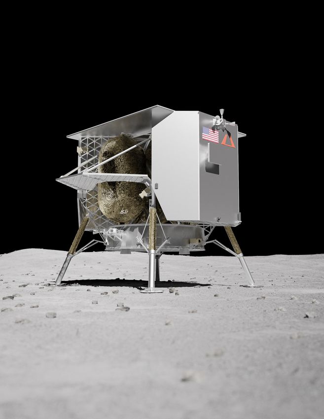
TABLE OF CONTENTS
ABOUT US............................................................................................................................................... 3
     What We Do.................................................................................................................................................................4
     Service Overview..........................................................................................................................................................5
     Payload Experience.......................................................................................................................................................6
     Astrobotic Lunar Services. . ..............................................................................................................................................7
     Lunar Orbit Delivery Locations.........................................................................................................................................8
     Lunar Surface Delivery Locations......................................................................................................................................9
PEREGRINE............................................................................................................................................. 10
     Peregrine Bus System....................................................................................................................................................11
        Mid-Latitude Configuration............................................................................................................................................12
        Polar Configuration.......................................................................................................................................................13
     Structure.................................................................................................................................................................... 14
     Propulsion.................................................................................................................................................................. 15
     Guidance, Navigation, and Control................................................................................................................................ 16
     Power........................................................................................................................................................................ 17
     Avionics..................................................................................................................................................................... 18
     Communications......................................................................................................................................................... 19
     Thermal Control..........................................................................................................................................................20
INTERFACES............................................................................................................................................ 21
     Mechanical Environment.. .............................................................................................................................................22
     Thermal Environment...................................................................................................................................................24
     Pressure and Humidity Environment. . ..............................................................................................................................26
        Pressure Environment. ................................................................................................................................................... 26
        Humidity Environment. .................................................................................................................................................. 26
     Particle and Containment Environment. . ..........................................................................................................................27
     Radiation Environment.................................................................................................................................................28
     Electromagnetic Environment........................................................................................................................................29
     Payload Types.............................................................................................................................................................30
     Payload Mounting Accommodations.. ............................................................................................................................. 31
     Payload Mounting Decks..............................................................................................................................................32
     Adapter Plates............................................................................................................................................................33
     Electrical Interfaces. . ....................................................................................................................................................34
     Release Mechanisms....................................................................................................................................................35
     Data Interfaces............................................................................................................................................................36
     Ground Segment......................................................................................................................................................... 37
MISSION OPERATIONS..............................................................................................................................38
     Landing Site...............................................................................................................................................................39
     Mission Profile............................................................................................................................................................40
     Trajectory................................................................................................................................................................... 41
     Descent Profile............................................................................................................................................................42
     Power Services............................................................................................................................................................43
     Data Services..............................................................................................................................................................44
     Egress Procedures.......................................................................................................................................................45
PAYLOAD INTEGRATION............................................................................................................................47
     Mission Timeline.........................................................................................................................................................48
     Integration.................................................................................................................................................................49
GLOSSARY..............................................................................................................................................50
     Glossary of Units......................................................................................................................................................... 51
     Glossary of Terms........................................................................................................................................................52
     Glossary of Documentation...........................................................................................................................................53
     Glossary of Milestones.................................................................................................................................................54
CONTACT US...........................................................................................................................................55
     Questionnaire.............................................................................................................................................................56

                                                                                         2                                                                     © Astrobotic 2020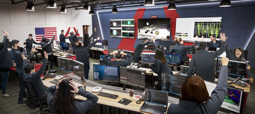
AB O U T US

     3        © Astrobotic 2020
WHAT WE DO
Astrobotic is a lunar logistics company providing end-to-end delivery services for payloads
to the Moon.

   PAYLOAD INTEGRATION                            LUNAR DELIVERY                         PAYLOAD SERVICES
    On each mission, Astrobotic works      Peregrine is launched on a commercially    Peregrine provides power and data
   with payload customers to integrate       procured launch vehicle and safely      services to payloads during transit to
  their payloads onto a single Peregrine     delivers payloads to lunar orbit and     the Moon and on the lunar surface.
               lunar lander.                           the lunar surface.

Each payload customer receives comprehensive support from contract signature to end of mission. The Payload
Customer Service Program equips the customer with the latest information on the mission and facilitates technical
exchanges with Astrobotic engineers to ensure payload compatibility with the Peregrine lunar lander and overall
mission success.

                                                              4                                              © Astrobotic 2020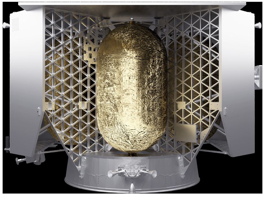
SERVICE OVERVIEW
Companies, governments, universities, non-profits, and individuals can send payloads to the
Moon at $1.2M per kilogram of payload to the lunar surface.

Standard payload delivery options include lunar orbit and the lunar surface where payloads may remain attached
to the lander, deploy from the lander for an independent mission, or hitch a ride on an Astrobotic lunar rover.

         LUNAR ORBIT                          LUNAR SURFACE                          DELIVERY ON ROVER
           $300,000/kg                            $1,200,000/kg                             $4,500,000/kg

For every kilogram of payload,                       1.0 Watt                   10 kbps
Peregrine provides:                                  POWER                      BANDWIDTH

   Additional power and                NOTE: Payloads less than 1 kg may be subject to
   bandwidth are available             integration fees. DHL MoonBox offers an affordable
   for purchase upon request.          alternative to send small items to the Moon.
                                       Prices start at $460.
   Please contact Astrobotic
   to learn more.                      Check it out at astrobotic.com

                                                        5                                              © Astrobotic 2020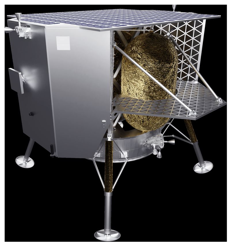
PAYLOAD EXPERIENCE

                  SERVICES AGREEMENT
                  Following contract signature, the payload customer is connected
              1   with their payload manager to begin development of a schedule and
                  an Interface Control Document.

                  TECHNICAL SUPPORT
                  Astrobotic supports the payload customer by hosting regular integration
              2   working group meetings, participating in payload design cycle reviews,
                  and facilitating payload testing with simulated lander interfaces.

                  INTEGRATION
              3   The payload is sent to the Astrobotic integration facility. Astrobotic
                  accepts the payload and integrates it onto Peregrine.

                  MISSION
                  The integrated lander is launched and commences its mission.
              4   The Astrobotic Mission Control Center connects the customer to
                  their payload during the flight to the Moon and on the lunar surface.

                                  6                                              © Astrobotic 2020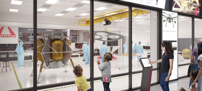
ASTROBOTIC LUNAR SERVICES
Astrobotic is here to support the success of your payload mission. The standard payload interfaces and services
are defined to enable nominal payload missions. This Payload User’s Guide (PUG) provides an overview of these
standard interfaces and services.
Astrobotic can accommodate payloads with needs outside of the standard interfaces and services at additional
cost. Please contact Astrobotic to discuss any nonstandard requests such as custom interfaces, accommodation
of large or unusual geometries, specific trajectory or landing site requirements, payload design consulting
services, etc.
The Payload Customer Service Program is a standard service for all payload customers to provide the tools
necessary to design a payload that successfully interfaces with Peregrine.

The following features are included as part of the program:

                              1      Availability for general and technical inquiries.

                             2       Bi-weekly technical exchanges with Astrobotic mission engineers.

     PAYLOAD
    CUSTOMER
     SERVICE
                             3       Access to the Astrobotic library of payload design resources and standards.

    PROGRAM

                             4       Technical feedback through payload milestone design reviews.

                             5       Facilitation of lander-payload interface compatibility testing.

NOTE: Access to materials within the Astrobotic library is not always restricted to
signed customers. Please contact Astrobotic for more information on obtaining the
latest version of any document referenced within the PUG.

                                                              7                                         © Astrobotic 2020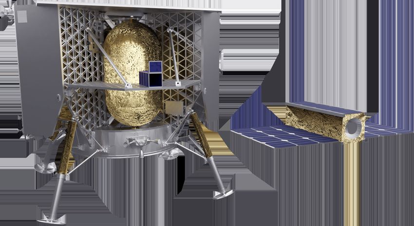
LUNAR ORBIT DELIVERY LOCATIONS
Peregrine can deliver payloads to lunar orbit as well as the lunar surface. While the trajectory can change
from mission to mission, Peregrine typically holds in three distinct Lunar Orbits (LO’s), and two are available
for payload deployment. The periapsis is consistent at 100 km while the apoapsis decreases through Lunar
Orbit Insertion (LOI) maneuvers from 8700 km to a circular 100 km. The orbital inclination is typically
determined by the surface landing site.

  LO1                                    LO2                                                         LO3
  100 km x 8700 km                       100 km x 750 km                                             100 km x 100 km

   LUNAR ORBIT 1 (LO1)
   The initial lunar orbit, LO1 is a highly elliptical orbit. Peregrine nominally spends 12 hours in LO1.
   Nonstandard payload deployment may be available in this orbit upon request.

   LUNAR ORBIT 2 (LO2)
   The next lunar orbit, LO2 is a stable elliptical orbit. The time Peregrine spends in LO2 depends on the
   launch date and subsequent trajectory as well as the orbital deployment schedule. All payload deployments
   are nominally planned for this orbit.

   LUNAR ORBIT 3 (LO3)
   The final lunar orbit, LO3 is a circular orbit. Peregrine nominally spends 72 hours in LO3 for descent
   preparations. Payload deployment is not supported in this orbit.

                                                           8                                                © Astrobotic 2020
LUNAR SURFACE DELIVERY LOCATIONS
The Peregrine product line is capable of supporting payload missions to locations of interest from the lunar
equator to the poles. Mission One will deliver payloads to a landing site near Lacus Mortis, 44°N, 25°E.

                                                              Polar

                                                                            M1:
                                                                        Lacus Mortis

                   Skylights,
                 Pits, or Caves

                                             Equatorial
                                                                                                          Far Side

                                         Craters

                                                              Polar

Starting with Mission Two, Peregrine will incorporate technology like Astrobotic’s Optical Precision Autonomous
Landing (OPAL) Sensor, a terrain relative navigation system to enable precision landing. This sensor, flown as a
technology demonstration on Mission One, will enable polar landings and other missions requiring precision
landing capabilities.

                                                          9                                           © Astrobotic 2020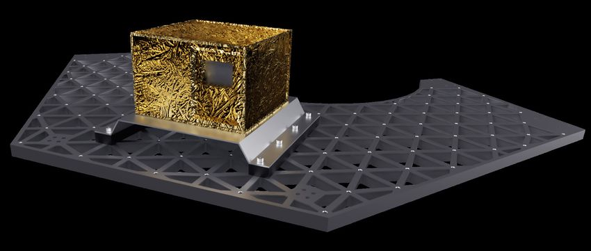
P EREGRI N E

     10        © Astrobotic 2020
PEREGRINE BUS SYSTEM
A core set of systems, known as the bus, are maintained for every Peregrine configuration. The lander
bus design enables safe payload delivery to lunar orbit and any latitude on the lunar surface. The bus can
be arranged, augmented, and adapted to the various payload delivery locations. This flexibility allows
Peregrine to accommodate a variety of payload types for science, exploration, marketing, resources, and
commemoration. Other alterations to the lander bus, such as additional sensors for precision landing or a
satellite communications relay for far-side operations, may be necessary depending on the specific mission.
The Peregrine Bus System is comprised of the following systems.
STRUCTURES
1 Provides mounting locations for payloads and lander systems.
PROPULSION
2 Maneuvers lander after separation from the launch vehicle.
GUIDANCE, NAVIGATION, AND CONTROL
3 Controls, orients, and flies the lander throughout the mission.
PEREGRINE POWER
BUS SYSTEM
4 Generates, stores, and distributes power to payloads and lander systems.
AVIONICS
5 Performs all command and data handling for the lander.
COMMUNICATIONS
6 Provides communication services between ground stations and the lander.
THERMAL CONTROL
7 Regulates and controls thermal interfaces for lander systems.
The following pages highlight the mid-latitude and polar configurations of the Peregrine bus and explore
each system in more detail. Additional configurations for lunar orbit, equatorial, far side, and many more
delivery locations are possible. Contact Astrobotic for more details on specific configurations.
11 © Astrobotic 2020MID-LATITUDE CONFIGURATION
Peregrine’s mid-latitude configuration is designed to land and operate at latitudes between 40° and 50° North
or South. The lander features side radiators and a top mounted solar panel. This configuration will be flown on
Astrobotic’s Mission One as a co-manifested payload aboard ULA’s Vulcan Centaur launch vehicle.
Top-Mounted
Solar Panel
Medium Propellant Tanks
Gain Antenna
Payload
Mounting Decks
Side-Mounted
Radiators Attitude Control
Thrusters
MID-LATITUDE
Lunar Surface Payload Delivery Capacity 100 kg
Surface Operations Duration 192 hours
12 © Astrobotic 2020POLAR CONFIGURATION
Missions to the polar regions of the lunar surface feature side-mounted solar panels to produce sufficient
power at higher latitudes and support payload needs. Lander avionics are mounted to a radiator at the top
of the lander.
Medium Gain High Gain Antenna
Antenna
Radiator
Sun Shield Attitude Control
Thrusters
Side-Mounted
Stretched Solar Panels
Propellant Tanks
Payload
Mounting Decks
POLAR
Lunar Surface Payload Delivery Capacity 100 kg
Surface Operations Duration 192+ hours
NOTE: Some polar landing sites have periods of continuous
sunlight that last longer than a lunar day at midlatitude.
13 © Astrobotic 2020STRUCTURE
Peregrine’s structure is strong, stiff, and lightweight for survivability during launch and landing. The bus
structure is manufactured out of aluminum alloy and is comprised of three primary components, the launch
vehicle adapter cone, isogrid shear panels, and two aluminum honeycomb enclosures. The standard physical
mounting interface for the payloads is optimized for the specific mission profile. For missions to the lunar
surface, four landing legs, designed to absorb shock and stabilize the craft on touchdown, are fastened to
the bus structure.
LAUNCH VEHICLE ADAPTER CONE
The launch vehicle adapter cone houses
the main engines. Additionally, it serves as
the adapter to the launch vehicle where a
releasable clamp band mates Peregrine to
the launch vehicle and enables separation.
ISOGRID SHEAR PANELS
The aluminum isogrid shear panels support
the secondary elements of the lander such as
fuel tanks, payload mounting decks, and the
solar panel. An internal truss structure ties the
four shear panels together and serves as a
central column for the structure.
Peregrine Structural Bus
ENCLOSURES
The aluminum honeycomb enclosures provide mounting surfaces and protection for lander avionics.
In some configurations these enclosures are also the primary radiators for the lander’s thermal system.
In other configurations they are converted to mounting surfaces for solar panels.
14 © Astrobotic 2020PROPULSION
The Peregrine propulsion system features five main engines and twelve Attitude and Control System (ACS)
engines powered by a pressure-fed hypergolic bipropellant, which does not require ignition because the fuel
and oxidizer combust on contact. The system features a proven hydrazine derivative, Mono-Methyl-Hydrazine
(MMH), as the fuel. The oxidizer is a solution of nitric oxide in dinitrogen tetroxide/nitrogen dioxide, 25%
Mixed Oxides of Nitrogen (MON-25).
ACS Thrusters
Fuel Tanks
Five Main Engines
Peregrine Propulsion Bus
Two tanks each of the fuel and oxidizer are spaced evenly about the craft with a fifth tank for the Helium
pressurant in the center. Peregrine’s main engines, located within the cone, are used for all major maneuvers.
Each of the engines produces 667 N of thrust and is pulsed for throttling. The ACS thrusters, grouped in clusters
of three and placed about the lander to ensure control with six degrees of freedom, maintain lander orientation
throughout the mission. The ACS engines each generate 45 N of thrust.
15 © Astrobotic 2020GUIDANCE, NAVIGATION, AND CONTROL
Peregrine’s Guidance, Navigation, and Control (GNC) system orients and flies the lander throughout
the mission to facilitate operations. GNC processes the inputs from an array of sensors, correcting for
idiosyncrasies, and uses them to revise the internal estimate of the lander’s position, attitude, and velocity
during flight. Commands to maneuver the lander are updated based on this estimate of the spacecraft’s
state. Earth-based ranging informs position and velocity state estimates for orbital and trajectory
correction maneuvers.
Input from the star tracker, sun sensors, and inertial measurement unit aid the GNC system in maintaining
a sun-pointing orientation, with the solar panel facing the Sun, during nominal cruise operations. During
landing operations, a Doppler LiDAR provides range and range rate information that guides the lander to
a safe landing at the target site.
OPTICAL PRECISION AUTONOMOUS
LANDING SENSOR
Astrobotic leads a team comprised of Moog Space
and Defense, Moog Broad Reach, NASA Jet Propulsion
Laboratory (JPL), and NASA Johnson Space Center (JSC)
developing the Optical Precision Autonomous Landing
(OPAL) Sensor. The OPAL Sensor is an imaging-based
terrain relative navigation package that will be flown as
a technology demonstration on Mission One and then
incorporated with the GNC system on the following
missions. The OPAL Sensor consists of a camera and
high performance computer, which uses images from
the camera and maps stored in the lander memory
to estimate the pose of the lander in real time.
OPAL Sensor Assembly
16 © Astrobotic 2020POWER
The lander power system is responsible for power storage, generation, distribution, and management. The
system is designed to be power positive, generating more power than it uses, for all phases of flight except
for descent to the lunar surface where the lander relies on battery power for a short period.
Peregrine stores energy in a space-grade lithium-ion battery. A panel of GaInP/GaAs/Ge triple junction solar
cells with heritage in orbital and deep space missions generates the lander’s power. The battery feeds into a 28
Vdc power rail from which unregulated and regulated power is distributed to all lander subsystems and payloads.
The battery is utilized during quick discharge activities, such as engine burns and attitude maneuvers, and during
phases of the mission where the solar panel is not generating power, such as in lunar shadow.
While in orbit, the solar panel is nominally
pointed towards the Sun to enable maximum
power generation. The solar panel is utilized to
provide battery charge and maintain lander and
payload operations. After descent to the lunar
surface the power system continues to provide
reliable power services to payloads through
the end of mission.
SOLAR PANEL CONFIGURATIONS
Missions to different latitudes on the lunar
surface require that the solar panels used on
Peregrine be reconfigured to optimize power
generation. Mid-latitude and equatorial landers
utilize top-mounted panels whereas polar missions
utilize side-mounted panels. Landers with side-
mounted panels perform a thermal control roll
during transit to ensure consistent power
generation. Peregrine Mid-Latitude Solar Panel Configuration
17 © Astrobotic 2020AVIONICS
Peregrine’s avionics perform all command and data handling for the lander, managing the various inputs and
outputs of the lander’s subsystems. The Integrated Avionics Unit (IAU) houses ten modules, or boards, with
distinct functionalities encompassing the major aspects of the avionics system like the power management
systems and the flight computer.
Other aspects, such as GNC flight sensor drivers and propulsion control units, are enclosed separately near the
relevant subsystem hardware. Peregrine’s flight computer consists of a 32-bit high-performance dual-core LEON
3 FT microprocessor. The computer employs radiation-hardened integrated circuits as well as fault-tolerant and
SEU-proof characteristics.
THE PAYLOAD COMPUTER
The payload computer, a pair of radiation-tolerant
FPGAs, is also housed within the IAU and manages
the individual payloads as well as their contractual
services. The payload computer monitors payload
power consumption and communicates directly
with the payloads. Commands from the payload
ground software are sent to the payload via the
payload computer and payload telemetry is
packaged for downlink to Earth. The payload
computer features Error Detection And Correction,
upset monitoring, and robust software with proven
networking standards.
Integrated Avionics Unit (IAU) Enclosure
FLIGHT HERITAGE
Peregrine’s avionics system is designed to be modular and reusable; this enables future Peregrine missions
to leverage the lessons learned and hardware developed for Mission One. While missions will utilize different
lander configurations, the core command and data handling system remains the same, maintaining reliability
for the product line.
18 © Astrobotic 2020COMMUNICATIONS
Peregrine’s communications system provides for lander commanding and telemetry. The communications
system also relays data between the payload customer and their payload throughout the mission. The lander
houses a high-powered and flight-heritage transponder to communicate with Earth. The lander-Earth connection
uses different frequencies within the X-Band range for uplink and downlink space communications.
Low Gain Antenna
Medium
Gain Antenna
WLAN Antenna
Peregrine Communications Bus
The lander utilizes multiple low gain antennas for optimal coverage during cruise and lunar orbit operations
and then switches to an actuated medium or high gain antenna following touchdown on the lunar surface for
increased bandwidth. The lander-payload connection is provided via Serial RS-422 or SpaceWire for wired
communication throughout the mission. Following landing, a 2.4 GHz IEEE 802.11n compliant WLAN modem
enables wireless communication between the lander and deployed payloads on the lunar surface. Peregrine
relays payload telecommands and telemetry in near real-time.
19 © Astrobotic 2020THERMAL CONTROL
The lander is designed to implement mainly passive methods to regulate its thermal environment. Radiators
are used to amass excess heat and radiate it out into space. Passive heat pipes are employed to direct excess
heat to colder regions of the lander where it is needed. Layers and coatings, such as Multi-Layer Insulation
(MLI), are used to protect components from undesired external thermal effects.
Avionics Avionics
Radiator Radiator
MLI Blankets
Peregrine Thermal Bus
Some active thermal control methods, heating or cooling, may be implemented to maintain particularly
stringent thermal conditions of sensitive critical components. The overall thermal design is highly mission-
specific as the lander may be either hot or cold-biased depending on the extreme thermal case of each
mission profile.
20 © Astrobotic 2020INT E R FACE S
21 © Astrobotic 2020MECHANICAL ENVIRONMENT
The Peregrine mechanical environment is enveloped by the launch phase. The following environments are
based on the mid-latitude configuration of Peregrine. These environments envelope 90% of payload mounting
locations; however, mission-specific configurations and payload placement may impact expected loads.
Astrobotic works with each customer to develop payload-specific environments for relevant testing and
analysis prior to integration.
SINE VIBRATION LOADS
Static axial and lateral accelerations are enveloped by the sine vibration environment. Astrobotic performs
a coupled loads analysis with the launch vehicle provider and develops sine vibration loads for each payload
based on mounting location, payload mass properties, launch vehicle, and the specific lander configuration.
Please contact Astrobotic for more details on sine vibration loads.
RANDOM VIBRATION LOADS
The random vibration loads for payloads are derived from the lander structure due to the acoustic
environment. These are the qualification loads for random vibration in all axes, a duration of 2 minutes per
axis may be assumed.
14.1 Grms
Acceleration Spectral Density (G2/Hz)
Frequency (Hz)
22 © Astrobotic 2020ACOUSTIC LOADS
Payloads are subjected to the highest acoustic levels at lift-off and during transonic flight. The expected
duration of these loads is less than 2 minutes. The acoustic qualification loads are shown below.
Sound Pressure Level (dB, ref: 20 kPa)
1/3 Octave Band Center Frequency (Hz)
SHOCK LOADS
Peregrine encounters multiple shock events during launch and injection. Shock events include the
launch vehicle fairing release, lander separation, and landing. Payloads may assume 5 shock events
with qualification loads as follows.
Shock Response (G peak)
Frequency (Hz)
NOTE: Payloads may reference GSFC-STD-7000A (GEVS) for more details
on payload random, shock, and acoustic environments.
23 © Astrobotic 2020THERMAL ENVIRONMENT
Peregrine encounters the following approximate thermal environments on a typical
reference mission.
0°C to 27°C PRE-LAUNCH
The integration and launch facilities are climate-controlled to provide this specific
temperature range.
0°C to 27°C LAUNCH
Throughout the Launch phase, the integrated Lander is encapsulated in an
environmentally controlled launch vehicle payload fairing.
-40°C to 60°C CRUISE
The thermal environment is significantly colder for objects in shadow and much
hotter for objects in direct sunlight.
-120°C to 100°C LUNAR ORBIT
The thermal environment is significantly colder for objects in shadow, particularly
during lunar eclipse, and much hotter for objects in direct sunlight, which can be
compounded by light and infrared radiation from the lunar surface.
-30°C to 80°C LUNAR SURFACE
The thermal environment is significantly colder for objects in shadow and much
hotter for objects in direct sunlight. This range is relevant for the nominal lunar
surface operations duration and does not include lunar night or missions to
equatorial latitudes.
NOTE: The corresponding thermal environments of the payload depend on
mounting location and the incident sunlight at that location throughout the
mission. Astrobotic works with each customer to develop payload-specific
environments for relevant system testing prior to payload integration.
24 © Astrobotic 2020Throughout flight, Peregrine is nominally oriented with the top-mounted solar panel facing
the Sun. As a result, the lander’s top-side receives the most incident solar radiation, and resulting heat, during
the Cruise and Lunar Orbit phases. Polar configurations by contrast perform a thermal control roll during Cruise
and Lunar Orbit, evenly heating the spacecraft and pointing the solar panels at the Sun.
Mid-Latitude Polar
The most extreme thermal environments occur during the Lunar Orbit phase when the lander cycles through
cold and hot as it passes through the Moon’s shadow, shown in the representative diagram below. Peregrine
nominally spends up to 24 hours in LO1 and 72 hours in LO3. The duration in LO2 is dependent on the trajectory
and orbital deployment concept of operations.
LO1 LO2 LO3
100 km x 8700 km 100 km x 750 km 100 km x 100 km
~11.5 hours in Sun ~120 minutes in Sun ~75 minutes in Sun
~0.5 hours in shadow ~40 minutes in shadow ~45 minutes in shadow
On the Lunar Surface, Peregrine is nominally oriented such that the avionics in Enclosure A are pointed towards
the lunar north pole where it is mostly or completely shadowed for the duration of lunar surface operations.
B
C A
D
The movement of the Sun throughout the lunar day and the reflection of light from the lunar surface creates
thermal environments highly specific to the payload’s mounting locations.
25 © Astrobotic 2020PRESSURE AND HUMIDITY ENVIRONMENT
PRESSURE ENVIRONMENT
Peregrine encounters the following approximate pressure environments on a typical
reference mission.
PRE-LAUNCH
101.25 kPa represents the average atmospheric pressure at sea level; the actual value depends on the
respective locations of the integration and launch facilities.
LAUNCH
This is a typical pressure drop curve for launch which envelopes the pressure drop for all other mission
phases. The pressure drop is expected to surpass –2.5 kPa/s only briefly during transonic flight as the
launch vehicle exceeds the speed of sound and will not exceed -5.0 kPa/s.
Pressure (kPa)
Time (s)
REMAINING MISSION
3.2×10⁻⁵ kPa represents the vacuum of the space environment.
HUMIDITY ENVIRONMENT
Peregrine encounters the following approximate humidity environments while on mission.
LAUNCH
The integration and launch facilities are climate-controlled to 50% ± 15% humidity. The higher humidity
values may occur during transportation and depend on the local climate of the facilities’ locations.
REMAINING MISSION
The vacuum of the space environment has 0% humidity.
26 © Astrobotic 2020PARTICLE AND CONTAINMENT ENVIRONMENT
The Peregrine encounters the following approximate particle and contaminant environments on
a typical reference mission.
PRE-LAUNCH
Planetary Protection regulations govern the Pre-Launch particle and contaminant environment. Assembly
and maintenance of the lander and payloads must occur in a 100k or ISO Class 8 cleanroom. The integration
and launch facilities provide suitable cleanrooms for Pre-Launch activities. The payload customer must ensure
compliance with Planetary Protection protocols prior to integration with the lander.
Astrobotic Headquarters and Integration Facility contains two ISO Class 8 cleanrooms for Integration.
CRUISE, LUNAR ORBIT, AND SURFACE
The firing of main and thruster engines expels a minute amount of propellant. Following touchdown on the lunar
surface, the propulsion system is made safe by venting excess helium pressurant, which may carry trace amounts
of fuel and oxidizer. These propellant residuals are unlikely to affect payloads; however, payload customers may
design for shielding of sensitive components if so desired.
SURFACE
During the landing procedure, Peregrine displaces an unknown amount of lunar regolith, which may take
several hours or days to fully settle. Lunar regolith is sharp and may cause damage to sensitive components.
Lunar regolith is also electrostatically charged, which may cause it to cling to payload surfaces. The payload
customer is responsible for identifying at-risk payload systems and implementing mitigation strategies such
as shielding or deployable dust covers if necessary.
27 © Astrobotic 2020RADIATION ENVIRONMENT
Peregrine encounters the following approximate ionizing radiation environments on a typical reference mission.
The Van Allen radiation belts contain energetic protons and electrons that are trapped in the Earth’s magnetic
field and generally follow the magnetic field lines. The overall structure of the Van Allen belts can be seen from
the highly simplified diagram in the figure below.
Low Earth Orbit (ELECTROMAGNETIC ENVIRONMENT
The lander and all payloads must be designed for compliance with MIL-STD-461G for radiated and
conducted emissions. The table below shows the appropriate testing to perform based on payload type,
defined on the following page. Please contact Astrobotic for additional information or the latest version
of the relevant Requirements for the Control of Electromagnetic Interference Emissions and Susceptibility
(MIL-STD-461G) document.
EMI CATEGORY REQUIREMENT APPLICABILITY
Conducted Emissions CE102 Active Payloads
CS101
CS114
Conducted Susceptibility Active Payloads
CS115
CS116
Radiated Emissions RE102 Active Payloads
Radiated Susceptibility RS103 Payloads with Antennas
These tests characterize the interference, susceptibility, and compatibility of the lander and payloads to
ensure appropriate electrical interfacing that does not induce significant interference, noise, or performance
degradation into the integrated system. Additionally, these tests inform compliance with other external
standards and regulations such as Range Safety. Please contact Astrobotic for the latest version of the
relevant Range Safety User Requirements Manual Volume 3 (AFSCMAN91-710V3) document.
29 © Astrobotic 2020PAYLOAD TYPES
Astrobotic recognizes four payload types. A payload may be either passive or active as well as either static
or deployable; this results in the four distinct payload types detailed below. The standard payload interfaces,
services, and operations are informed by the payload type.
STATIC DEPLOYABLE
Static Passive Deployable Passive
PASSIVE
• Remains attached to lander • Detaches from lander
• Does not perform mission tasks • Does not perform mission tasks
Example: Memorabilia Example: Surface time capsule
Static Active Deployable Active
ACTIVE
• Remains attached to lander • Detaches from lander
• Performs mission tasks • Performs mission tasks
Example: Science instrument Example: Rover
Peregrine provides payloads with standard and well-defined interfaces to support their missions. The following
pages outline the standard physical, functional, and ground segment interfaces
for payloads. The service interfaces, which provide power and data to payloads, vary both by payload type
and mission phase. Service interfaces are described in the Mission Operations section. Astrobotic is able
to accommodate nonstandard interfaces upon request.
Please contact Astrobotic for additional information or the latest version of the Interface Definition Document
(IDD), which provides a comprehensive description of the standard interfaces.
30 © Astrobotic 2020PAYLOAD MOUNTING ACCOMMODATIONS
Peregrine accommodates a wide range of payloads by providing a flexible mounting solution to accommodate
payload pointing and mounting requirements. Two open isogrid aluminum decks serve as the standard payload
mounting structure, a smaller deck is utilized for some deployable payloads. Alternate mounting locations, such
as on the vertical enclosures or internal shear panels, are available as a nonstandard service; please contact
Astrobotic for additional information.
Above Deck
Below Deck
Enclosure Deck
Standard Payload Mounting Envelopes
Astrobotic provides a volume about the payload mounting decks designated for safe and simple accommodation
of payloads, known as the payload envelope. The envelope ensures safe stowage during flight and sufficient
ground clearance upon landing for payloads. Astrobotic works with each payload customer to define a section
of this envelope, which the payload may use as desired.
As a standard service, Astrobotic can accommodate payloads up to 0.38 m tall below the payload mounting
decks and 0.57 m tall above the decks. Depending on the landing conditions, the ground clearance from the
bottom of the payload envelope ranges between 0.40 m and 0.80 m.
Payload operations outside of the envelope are permitted during the Surface phase. Such operations must be
discussed and scheduled with Astrobotic. Egress procedures may also be performed during the Lunar Orbit
phase as discussed and scheduled with Astrobotic.
31 © Astrobotic 2020PAYLOAD MOUNTING DECKS
The payload mounting decks are the primary mounting location for payloads, featuring a standardized bolt
pattern for simplified payload mounting. Most Peregrine configurations feature two standard decks and a deck
below one avionics enclosure for smaller payloads.
Each standard deck offers approximately 0.5 m2 of mounting area per side. The same bolt pattern is provided
on both sides of these decks. Locking helicoil inserts are sized for standard M5 bolts and are spaced 75 mm
apart, from center to center. The small deck features approximately 0.2 m2 of mounting area and payloads may
only mount below the deck.
0.65 m 0.36 m
0.11 m
0.21 m 0.67 m
0.41 m
0.22 m 0.075 m
0.075 m
0.07 m
0.075 m
0.32 m
R 0.30 m
0.075 m
Please contact Astrobotic for more detailed drawings and dimensions of the payload mounting decks.
Astrobotic assigns specific bolt holes to every
payload based on their size and mounting location
requirements. Astrobotic provides a suitable number
of helicoil inserts to each payload as determined by
the payload size and allotted number of bolt holes.
The appropriate method for attaching a payload
to its assigned helicoil inserts is illustrated in the
diagram to the right. The lander deck and Astrobotic-
supplied helicoil inserts are shown in gray whereas
customer-supplied components are shown in blue.
Two payloads may utilize the same bolt hole from
opposite sides of the deck as each side of the
payload mounting deck is provided its own
locking helicoil insert.
32 © Astrobotic 2020ADAPTER PLATES
Payload placement on the lander is an iterative and cooperative process between Astrobotic and the payload
customer. The final assignment of bolt holes to each payload occurs once the manifest is filled and ICD’s are
signed. Astrobotic recommends payloads utilize an adapter plate, which allows the payload design to progress
independently of the assignment of bolt holes. The diagram below illustrates a typical payload adapter plate
design. Adapter plates are considered part of a payload’s mass allocation.
Payload Payload
Mounting Deck
Thermal and Payload
Vibration Isolation Adapter Plate
Additionally, the adapter plate can be utilized to dampen loads as experienced by the payload. It can also
simplify the provision of the required thermal characteristics as well as the implementation of the required
grounding, bonding, and isolation techniques at the payload mounting interface to the lander.
THERMAL INTERFACES
The payload must implement a thermally isolating connection to the lander, defined as a conductance of
< 0.1 W/K. This allows the payload to more effectively regulate its own thermal environment using passive
methods, such as radiators and coatings, or active methods, such as internal heaters.
GROUNDING, BONDING, AND ISOLATION INTERFACES
Peregrine operates with a single-point ground architecture. Payloads must conform to this approach by
employing proper grounding, bonding, and isolation schemes within their own payload design and by providing
contact points for the payload structural and conductive elements as well as internal electrical circuit common
ground, which Astrobotic connects to the lander chassis for grounding.
33 © Astrobotic 2020ELECTRICAL INTERFACES
Astrobotic provides power and data services through a Standard Electrical Connector (SEC). The SEC is a
Glenair SuperNine connector of the MIL-DTL-38999 Series III screw type connector. The connector is available
in a regular and small size, each with a standard pin configuration providing the contacts illustrated below.
Please contact Astrobotic for the specific SEC part number for your payload.
REGULAR SEC
Power
SMALL SEC
Power Signal
Data
Timing
Power Return
Not Connected
POWER
Payloads are allocated two power circuits as a standard service. One is used for payload operations and if
necessary, heater power. The other power circuit is used to perform deployments or actuations within the
payload. The power provided is 28 ± 5% Vdc and the power circuits are current-regulated, current-monitored,
reverse-voltage protected, and over-voltage-protected.
DATA
Data circuits are available in either Serial RS-422 or SpaceWire configurations. Both data circuits support
time at the tone, a time synchronization service that enables payloads to synchronize their internal clock with
the lander and by extension UTC time. Payloads requiring the use of SpaceWire for additional data bandwidth
must use the regular size SEC.
34 © Astrobotic 2020RELEASE MECHANISMS
Payloads may deploy from Peregrine in lunar orbit or on the lunar surface. Deployable payloads require
a release mechanism to detach from the lander. The customer is responsible for the selection, procurement,
testing, and integration of the release mechanism they deem most suitable for their payload design in
accordance with the Astrobotic guidelines and requirements.
LUNAR SURFACE DEPLOYMENTS
For lunar surface deployable payloads, Astrobotic recommends the use of hold-down and release
mechanism style devices, but the customer may select the device most suited to the payload design
if it meets the following requirements:
• Non-pyrotechnic
• Creates minimal debris
• Imparts no shocks greater than 300 g’s on the lander upon actuation
• Is housed within the payload unit
LUNAR ORBIT DEPLOYMENTS
Due to the mission-critical nature of orbital payload deployments prior to landing, Astrobotic requires the use
of a proven release mechanism design for lunar orbit deployable payloads. Please contact Astrobotic for more
details on lunar orbit deployable payloads.
Peregrine provides power services and power release signal services to the SEC interface. The payload
customer is responsible for integrating the release mechanism into their payload design such that it correctly
interfaces with these provided services and employs the appropriate arm and fire techniques to satisfy Range
Safety requirements. Please contact Astrobotic for the latest version of the Range Safety document.
35 © Astrobotic 2020DATA INTERFACES
Peregrine uses standard, well-defined data interfaces to simplify payload integration. Wired data services are
provided through the SEC. Therefore, wired data services are available only while the payload is attached to
the lander. Wireless data services are available to surface deployable payloads following separation from the
lander. Orbit deployable payloads must establish an independent communication connection with Earth
following separation from the lander.
NETWORK PROTOCOLS
Payloads may select between the three networking protocols to interface with the lander. Surface deployable
payloads are recommended to select a wired data interface for communications prior to separation from the
lander in addition to the wireless data interface.
• Serial RS-422, Serial Line IP (SLIP), and User Datagram Protocol (UDP)
• SpaceWire high-speed wired communication
• 2.4 GHz 802.11n WLAN wireless communication with IP and UDP
NETWORK ARCHITECTURE
Payload telemetry and telecommands are transmitted from the lander to the Astrobotic Mission Control Center
and then to the Payload Mission Control Centers without modification of payload data. Astrobotic contracts
ground stations to communicate with Peregrine using X-Band for uplink and downlink. One-way latency in the
connection between the customer and their payload on the Moon is nominally 4 seconds, although increases
in latency may occur during some mission events.
Serial RS-422/ 802.11n
SpaceWire WLAN
Attached
Payload
Peregrine Deployed
Payload
PMCC
X-Band Uplink
X-Band Downlink
Virtual Private
Network (VPN)
PMCC AMCC Ground Station
36 © Astrobotic 2020GROUND SEGMENT
The Astrobotic Mission Control Center (AMCC) serves as the data hub for Peregrine missions, providing
standardized, transparent, and safe networking to payload customers.
Payload Mission Control Centers (PMCCs) may be located adjacent to or remotely from the AMCC. Payload
customers are given access to a secure and private part of the AMCC network via Virtual Private Network (VPN).
Payloads that choose to operate their payloads adjacent to the AMCC do so from the Payload Operations Area.
Customers may implement custom PMCC applications using whatever hardware or software is necessary to
monitor and control the payload.
Rendering of the Astrobotic Mission Control Center in Pittsburgh, PA.
Astrobotic delivers payload telecommands and telemetry without modification. This system means the customer
does not need to consider the different mediums and channels traversed by their data packets.
All payload telecommands and telemetry are securely addressed, and the AMCC and lander verify each packet’s
meta-data for compliance, ensuring safe transmissions. Customer data is not opened or reformatted allowing for
payloads to implement encryption or other data security techniques.
Each payload customer is required to provide an on-site representative at the AMCC during mission operations
for rapid response to off-nominal situations. This requirement may be waived for static passive payload types.
37 © Astrobotic 2020MISSIO N O PER AT I O N S
38 © Astrobotic 2020LANDING SITE
PRECISION LANDING
Each Peregrine mission targets a landing ellipse in a region of interest based on the mission and payload
requirements. Starting with Mission 2, Peregrine will utilize Astrobotic’s Optical Precision Autonomous Landing
(OPAL) Sensor to dramatically improve the landing accuracy from a 24 km x 6 km ellipse to a 100 m x 100 m
ellipse. Since GPS is not available at the Moon and other planets, the OPAL Sensor uses on-board cameras and
computer vision algorithms to detect features on the lunar surface and match these features to onboard maps to
provide position updates during landing. Robust, high-speed image processing allows Peregrine to accurately
determine its pose as it descends towards the surface.
C
A
B B
C
A
Early version of the OPAL sensor autonomously selects a hazard-free landing site
for the Masten Space Systems Xombie Rocket.
EFFECTIVE SLOPES
Potential landing sites are analyzed based on a wide array of variables; one of the most important being
effective slope. The effective slope takes into account natural slopes in the topography and the presence of
rocks. Sites are typically selected with an effective slope ≤ 10°. Sites with a maximum expected rock height
of 0.3 m are preferred. Improvements to the lander system such as the terrain relative navigation system will
enable Astrobotic to select many more landing sites that meet these criteria.
LOCAL LANDING TIME
Once a landing site has been selected, Astrobotic plans a mission to maximize payload operation time on the
lunar surface. For Mission One, Peregrine will land 55-110 hours after sunrise. A lunar day, from local sunrise
to sunset on the Moon, is equivalent to 354 hours, or approximately 14 Earth days. At mid-latitudes, Peregrine
nominally operates for 192 hours, or 8 Earth days, following landing. Some polar missions may take advantage
of unique lighting conditions to operate for longer than a single lunar day.
39 © Astrobotic 2020MISSION PROFILE
The Peregrine mission profile encompasses five distinct phases, beginning with payload
integration to the lander and concluding at the end of the mission.
Payload Integration with Peregrine
PRE-LAUNCH PHASE
5 – 9 Months Includes preparation activities for launch including lander acceptance testing,
arrival at the launch site, and integration with the launch vehicle.
Launch Vehicle Lift-Off
LAUNCH PHASE
1 – 3 Hours Includes transit from the Earth’s surface to a highly elliptical Earth orbit onboard the
launch vehicle.
Peregrine Separation from Launch Vehicle
CRUISE PHASE
3 – 33 Days Includes the lander’s Earth orbit, Trans-Lunar Injection (TLI), and other lander
maneuvers while preparing to enter lunar orbit.
Peregrine Insertion into Lunar Orbit
LUNAR ORBIT PHASE
4 – 25 Days Includes all lunar orbit injection maneuvers, orbital payload deployments, and
descent to the lunar surface.
Peregrine Touchdown on the Lunar Surface
SURFACE PHASE
8+ Days Includes all surface activities such as surface rover deployments, payload data
acquisition, and imaging of the lunar surface.
End of Mission
40 © Astrobotic 2020TRAJECTORY
Astrobotic selects a specific trajectory for every mission based on launch profile and landing
site. A generic trajectory, typical for Peregrine missions, is shown below.
1 Launch to High Elliptical Orbit Aboard the Launch Vehicle
2 Separation from the Launch Vehicle
3 Perigee Raise Maneuver
4 TLI Maneuver
5 Cruise Through Cislunar Space
6 Lunar Orbit Insertion (LOI) Maneuver 4
7 Lunar Orbit Hold 1
2
8 Autonomous Descent Operations
9 Landing on the Lunar Surface
5
3
7
9
8
6
41 © Astrobotic 2020DESCENT PROFILE
Descent operations take Peregrine from lunar orbit safely to the surface. This phase of flight
is completed autonomously by the lander.
1 2 3 4
UNPOWERED POWERED TERMINAL TERMINAL
DESCENT DESCENT DESCENT DESCENT NADIR
Peregrine initiates descent As Peregrine approaches The OPAL Sensor and Peregrine descends
with a braking maneuver the surface, guided by the Doppler LiDAR inform vertically and maintains
and then coasts, using only OPAL Sensor and Doppler targeted guidance activity constant vertical velocity
attitude control thrusters to LiDAR, powered descent to the landing site, reducing from 30 m altitude until
maintain orientation. commences; here the main horizontal velocity. touchdown.
engines fire continuously to
slow down Peregrine.
100 km – 15 km
15 km to 1 m
1 km to 300 m
300 m to Touchdown
42 © Astrobotic 2020POWER SERVICES
Peregrine allocates power services based on payload mass, with several modes available to fit the payload
concept of operations. Additional power services are available for purchase; please contact Astrobotic for more
details. Peregrine defines the following service modes for payloads.
OFF No power is provided to payloads.
NOMINAL 1.0 W per kilogram of payload.
PEAK 2.5 W per kilogram of payload as scheduled by Astrobotic.
RELEASE 30 W peak payload power for approximately 60 seconds.
Power service modes provided to payloads change by mission phase as described below.
PRE-LAUNCH LAUNCH CRUISE LUNAR ORBIT SURFACE
< 20 minutes < 20 Minutes
OFF As Scheduled Entire Phase per lander per Lander N/A
maneuver Maneuver 1
NOMINAL As Scheduled N/A Default State Default State Default State
PEAK As Scheduled N/A N/A N/A As Scheduled
RELEASE As Scheduled N/A N/A As Scheduled 2 As Scheduled 3
1 Powered descent lasts two hours and is the only lander maneuver to last more than 20 minutes.
2 Only payloads delivered to lunar orbit are provided release power services in lunar orbit.
3 Only payloads with deployable or actuated elements on the lunar surface are provided release
power services on the surface.
Power services are provided through the SEC. Therefore, power services are available only while the payload is
attached to the lander. Deployable payloads take full control of their own power generation and consumption
following release from the lander.
43 © Astrobotic 2020You can also read