PHC10-3 PLUS installation guide - PHC10-3 PLUS installation guide Document part number: H-1000-0077-03-A - Renishaw resource centre
←
→
Page content transcription
If your browser does not render page correctly, please read the page content below

PHC10-3 PLUS installation guide

www.renishaw.com

PHC10-3 PLUS installation guide
Document part number: H-1000-0077-03-A

Issued 05 2021                           1
PHC10-3 PLUS installation guide

www.renishaw.com

General information
© 2012 ‐ 2021 Renishaw plc. All rights reserved.

This document may not be copied or reproduced in whole or in part, or transferred to any other media or language by any means, without the
prior written permission of Renishaw.

Disclaimer
WHILE CONSIDERABLE EFFORT WAS MADE TO VERIFY THE ACCURACY OF THIS DOCUMENT AT PUBLICATION, ALL WARRANTIES,
CONDITIONS, REPRESENTATIONS AND LIABILITY, HOWSOEVER ARISING, ARE EXCLUDED TO THE EXTENT PERMITTED BY LAW.

RENISHAW RESERVES THE RIGHT TO MAKE CHANGES TO THIS DOCUMENT AND TO THE EQUIPMENT, AND/OR SOFTWARE AND THE
SPECIFICATION DESCRIBED HEREIN WITHOUT OBLIGATION TO PROVIDE NOTICE OF SUCH CHANGES.

Trade marks
RENISHAW®, the probe symbol and REVO® are registered trade marks of Renishaw plc.

Renishaw product names, designations and the mark ‘apply innovation' are trade marks of Renishaw plc or its subsidiaries.

Other brand, product or company names are trade marks of their respective owners.

WEEE

The use of this symbol on Renishaw products and / or accompanying documentation indicates that the product should not be mixed with
general household waste upon disposal. It is the responsibility of the end user to dispose of this product at a designated collection point for
waste electrical and electronic equipment (WEEE) to enable reuse or recycling. Correct disposal of this product will help to save valuable
resources and prevent potential negative effects on the environment. For more information, please contact your local waste disposal service
or Renishaw distributor.

Warranty
Unless you and Renishaw have agreed and signed a separate written agreement, the equipment and/or software are sold subject to the
Renishaw Standard Terms and Conditions supplied with such equipment and/or software, or available on request from your local Renishaw
office.

Renishaw warrants its equipment and software for a limited period (as set out in the Standard Terms and Conditions), provided that they are
installed and used exactly as defined in associated Renishaw documentation. You should consult these Standard Terms and Conditions to find
out the full details of your warranty.

Equipment and/or software purchased by you from a third-party supplier is subject to separate terms and conditions supplied with such
equipment and/or software. You should contact your third-party supplier for details.

Issued 05 2021                                                                                                                            2
PHC10-3 PLUS installation guide

www.renishaw.com

Care of equipment
Renishaw probes and associated systems are precision tools used for obtaining precise measurements and must therefore be treated with
care.

Changes to Renishaw products
Renishaw reserves the right to improve, change or modify its hardware or software without incurring any obligations to make changes to
Renishaw equipment previously sold.

Company registration details
Renishaw plc. Registered in England and Wales. Company no: 1106260. Registered office: New Mills, Wotton-under-Edge, Gloucestershire,
GL12 8JR, UK.

Packaging
To aid end user recycling and disposal the materials used in the different components of the packaging are stated here:

 Packaging component                Material                            94/62/EC code                      94/62/EC number
 Outer box                          Corrugated fibreboard               PAP                                20
 Packing foam                       Cross-linked Polyethylene           LDPE                               4
 Bag                                Low density Polyethylene            LDPE                               4

Issued 05 2021                                                                                                                    3
PHC10-3 PLUS installation guide

www.renishaw.com

Product compliance
EU declaration of conformity
Contact Renishaw plc or visit www.renishaw.com/EUCMM for the full EU declaration.

UK declaration of conformity
Contact Renishaw plc or visit www.renishaw.com/UKCMM for the full UK declaration.

EMC conformity
This equipment must be installed and used in accordance with this installation guide. This product is intended for industrial use only and
should not be used in a residential area or connected to a low voltage power supply network which supplies buildings used for residential
purposes.

FCC (USA only)
Information to user (47 CFR 15.105)
This equipment has been tested and found to comply with the limits for a Class A digital device, pursuant to Part 15 of the FCC rules. These
limits are designed to provide reasonable protection against harmful interference when the equipment is operated in a commercial
environment. This equipment generates, uses, and can radiate radio frequency energy and, if not installed and used in accordance with the
instruction manual, may cause harmful interference to radio communications. Operation of this equipment in a residential area is likely to
cause harmful interference, in which case you will be required to correct the interference at your own expense.

Information to user (47 CFR 15.21)
The user is cautioned that any changes or modifications not expressly approved by Renishaw plc or authorised representative could void the
user's authority to operate the equipment.

Equipment label (47 CFR 15.19)
This device complies with part 15 of the FCC Rules. Operation is subject to the following two conditions:

1. This device may not cause harmful interference.
2. This device must accept any interference received, including interference that may cause undesired operation.

Issued 05 2021                                                                                                                          4
PHC10-3 PLUS installation guide

www.renishaw.com

ICES-001 (Canada only)
This ISM device complies with Canadian ICES-001.

Cet appareil ISM est conforme à la norme ICES‐001 du Canada.

REACH regulation
Information required by Article 33﴾1﴿ of Regulation ﴾EC﴿ No. 1907/2006 ﴾“REACH”﴿ relating to products containing substances of very high
concern (SVHCs) is available at:

www.renishaw.com/REACH

China RoHS
Contact Renishaw plc or visit www.renishaw.com/ChinaRoHSCMM for the full China RoHS tabulation.

Issued 05 2021                                                                                                                      5
PHC10-3 PLUS installation guide

www.renishaw.com

International safety instructions
BG ‐ ПРЕДУПРЕЖДЕНИЕ
Моля, обърнете на приложение 1 и прочетете инструкциите за безопасност на вашия собствен език, преди за разопаковате и
монтирате този продукт.

CZ ‐ VÝSTRAHA
Před rozbalením a instalací tohoto výrobku si přečtěte bezpečnostní pokyny ve vlastním jazyce uvedené v příloze 1.

DA - ADVARSEL
Læs sikkerhedsinstrukserne i Appendix 1 FØR udpakning og installation af dette produkt.

DE - WARNHINWEIS
Bevor Sie dieses Produkt auspacken und installieren, konsultieren Sie bitte Anhang 1 und lesen Sie die Sicherheitshinweise in Ihrer Sprache.

EL ‐ ΠΡΟΕΙΔΟΠΟΙΗΣΗ
Γυρίστε στο Κεφάλαιο 1 και διαβάστε τις οδηγίες ασφαλείας στη δική σας γλώσσα προτού ανοίξετε αυτό το προϊόν για να το
εγκαταστήσετε.

EN - WARNING
Before unpacking and installing this product, please consult Appendix 1 and read the safety instructions in your language.

ES - ADVERTENCIA
Consulte el apéndice 1 y lea las instrucciones de seguridad en su idioma antes de desempaquetar e instalar este producto.

ET - HOIATUS
Palun vaadake 1. lisa ning lugege enne selle toote lahtipakkimist ja paigaldamist ohutusjuhend läbi.

FI - VAROITUKSIA
Lue liitteessä 1 olevat omalla kielelläsi kirjoitetut turvaohjeet ennen tämän tuotteen pakkauksen avaamista ja asentamista.

FR - AVERTISSEMENT
Consulter l'annexe 1 et les instructions de sécurité dans votre propre langue avant de déballer et d'installer ce produit.

Issued 05 2021                                                                                                                        6
PHC10-3 PLUS installation guide

www.renishaw.com

GA - RABHADH
Téigh chuig aguisín 1 agus déan na treoracha sábháilteachta a léamh i do theanga féin le do thoil sula ndéantar an táirge seo a dhíphacáil
agus a shuiteáil.

HR - NAPOMENA
Prije nego što proizvod izvadite iz ambalaže i ugradite ga, otvorite Prilog 1 i pročitajte sigurnosne upute na svom jeziku.

HU – FIGYELMEZTETÉS
A termék kicsomagolása és telepítése előtt olvassa el az 1. számú függelékben található, az Ön anyanyelvén hozzáférhető biztonsági
utasításokat.

IT - AVVISO
Prima di aprire ed installare questo prodotto, leggere le istruzioni di sicurezza nella vostra lingua riportate nell'Appendice 1.

JA ‐ 警告
この製品を箱から取り出し設置する前に、付録 1 に記載された安全性に関する注意書きをお読みください。

LT – ĮSPĖJIMAS
Prieš išpakuodami ir įdiegdami produktą, turite grįžti prie 1 priedo ir perskaityti nurodymus dėl saugos savo kalba.

LV – BRĪDINĀJUMS
Pirms šī izstrādājuma izsaiņošanas un uzstādīšanas izskatiet 1. pielikumā sniegtās drošības instrukcijas savā valodā.

MT - TWISSIJA
Jekk jogħġbok mur f'appendiċi 1 u aqra l‐istruzzjonijiet tas‐sigurtà fil‐lingwa tiegħek qabel ma toħroġ dan il‐prodott mill‐ippakkjar u
tinstallah.

NL - WAARSCHUWING
Ga naar appendix 1 en lees de veiligheidsinstructies in uw eigen taal, voordat u dit product uitpakt en installeert.

PL ‐ OSTRZEŻENIE
Przed rozpakowaniem i zainstalowaniem tego produktu prosimy o zapoznanie się z Dodatkiem 1 i przeczytanie zaleceń dotyczących
bezpieczeństwa w danym języku.

PT ‐ ADVERTÊNCIA
Você deve retornar ao Anexo 1 e ler as instruções de segurança em seu idioma antes de desembalar e instalar este produto.

Issued 05 2021                                                                                                                            7
PHC10-3 PLUS installation guide

www.renishaw.com

RO - AVERTISMENT
Înainte de a desface ambalajul şi a instala acest produs, vă rugăm să căutaţi Anexa 1 şi să citiţi cu atenţie instrucţiunile de siguranță, în limba
română.

SK ‐ VÝSTRAHA
Pred rozbalením a inštaláciou tohto produktu si pozrite prílohu 1 a prečítajte si bezpečnostné pokyny vo vašom jazyku.

SL - OPOZORILO
Preden izdelek vzamete iz embalaže in ga vgradite, odprite Prilogo 1 in preberite varnostna navodila v svojem jeziku.

SV - VARNING
Gå till bilaga 1 och läs säkerhetsinstruktionerna på ditt eget språk innan du packar upp och installerar denna produkt.

TW ‐ 警告
在拆開和安裝本產品之前,請翻頁至附錄 1 閱讀母語的安全指示。

中文 — 警告
在拆包和安装本产品之前,请翻到附录1,阅读中文版安全说明。

Issued 05 2021                                                                                                                               8
PHC10-3 PLUS installation guide

www.renishaw.com

Warnings
Pinch hazards exist between moving parts and between moving and static parts. Do not hold the probe head during movements, or when
manually changing a probe.

Beware of unexpected movement. The user should remain outside the full working envelope of probe head / extension / probe combinations.

In all applications involving the use of machine tools or CMMs, eye protection is recommended.

For instructions regarding the safe cleaning of Renishaw products, refer to the maintenance information in the relevant product
documentation.

Remove power before performing any maintenance operations.

Refer to the machine supplier's operating instructions.

It is the machine supplier's responsibility to ensure that the user is made aware of any hazards involved in operation, including those
mentioned in Renishaw product documentation, and to ensure that adequate guards and safety interlocks are provided.

Under certain circumstances the probe signal may falsely indicate a probe-seated condition. Do not rely on probe signals to stop machine
movement.

If the equipment is used in a manner not specified by the manufacturer, the protection provided by the equipment may be impaired.

The expected method of providing an emergency stop for Renishaw products is to remove power.

Issued 05 2021                                                                                                                            9
PHC10-3 PLUS installation guide

www.renishaw.com

Safety
If the equipment is used in a manner not specified by the manufacturer, the protection provided by the equipment may be impaired. There are
no user serviceable parts inside the equipment.

The PHC10-3 head controller is to be used with the provided PSU.

 PSU electrical ratings
 Supply voltage                                                         100 V - 240 Vac +10% -10%
 Frequency range                                                        50 Hz to 60 Hz
 Power consumption                                                      40 W max
 Transient voltages                                                     Installation category II

PHC10-3 is isolated from ac power by disconnection of the IEC mains connector from the supplied PSU. If any additional means of isolation is
required, it must be specified and fitted by the machine manufacturer or installer of the product. The isolator / disconnection device must be
sited within easy reach of the operator and comply with any applicable national wiring regulations for the country of installation.

Issued 05 2021                                                                                                                        10
PHC10-3 PLUS installation guide

www.renishaw.com

Environmental conditions
The following environmental conditions exceed those as defined in BS EN 61010-1:2010:

Indoor use                                                          IP30 (no protection against water)
Altitude                                                            Up to 2000 m
Operating temperature                                               0 °C to +50 °C
Storage temperature                                                 ‐10 °C to +70 °C
Relative humidity                                                   80% maximum for temperatures up to +31 °C
                                                                    Linear decrease to 50% at +50 °C
Pollution degree                                                    2

Issued 05 2021                                                                                                  11
PHC10-3 PLUS installation guide www.renishaw.com References and associated documents Title Document number Installation and user's guide: PH10 PLUS H-1000-7592 Installation and user's guide: PH10M-iQ PLUS H-1000-7564 User's guide: HCU2 H-1000-5361 Installation guide: PICS H-1000-5000 USB driver package for PHC10-3 PLUS - Issued 05 2021 12
PHC10-3 PLUS installation guide
www.renishaw.com
Introduction
The guide gives information on physical installation, system connections, communications and interface settings, as well as assistance in fault-
finding during the installation of PHC10-3 PLUS.
WARNING: No attempt should be made to connect the PH10 PLUS system to any other any other system components as
incompatibility will result in damage to the product.
The guide should be read in conjunction with the PH10 PLUS series user's guide in order to fully understand the system's features, capabilities
and operation.
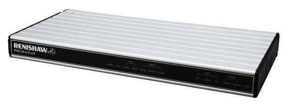
The PH10 PLUS series of motorised probe heads can only be used in conjunction with the PHC10-3 PLUS when part of an OEM system
installation. PHC10-3 PLUS has replaced the PHC10-2 and provides support for RS232 and USB communications (IEEE is no longer
supported). PHC10-3 PLUS uses an external power supply for the PH10 PLUS series of heads, manages all the head functions and
communicates via a suitable interface with the CMM's computer. PHC10-3 PLUS does not manage the probe functions but does have the
provision for an interface to be fitted.
Issued 05 2021 13PHC10-3 PLUS installation guide
www.renishaw.com
Rear panel layout
Key Description
1 9-way D-type plug for PICS output
2 9-way D-type connector to HCU2
3 25-way D-type plug RS232 communications connector to CMM
computer
4 USB type “B” socket
5 PHC10-3 PLUS configuration switches
6 15-way D-type connector to probe head
7 7-pin DIN raw probe connector to probe interface or multiwire input
for internal interfaces
8 DC power jack
9 Equipment bond point
10 Controller reset button
Issued 05 2021 14PHC10-3 PLUS installation guide
www.renishaw.com
PHC10-3 PLUS configuration switches
PHC10-3 PLUS switch settings
PHC10-3 PLUS switch Function Up Down
Communications
1# Baud rate
2# Baud rate
3# Baud rate
4*# Stop bit 2 stop bits 1 stop bit
5*# CTS protocol CTS on CTS off
6*# LF protocol LF on LF off
9 Command set Extended Basic
Interface
7 PICS configuration PPOFF - active during head index PPOFF - inactive during head
index
8 HCU2 PROBE/DAMP/RESET Enabled Disabled
10 Probe reseat time Extended Standard
11 Interface connection PICS / 7 pin DIN 5-pin DIN
12 Output configuration PICS DIN
13 Machine cable isolation Machine cable Multiwire
* Operational only when basic command set selected (switch 9 down).
# Not required for USB operation default position = down.
NOTE: Press the reset button after making switch changes.
Conversion from PHC10-2 to PHC10-3 PLUS
PHC10-3 PLUS is designed to be a plug in functional replacement for PHC10-2. There are some differences which the user needs to be aware
of, the connectors have been rearranged on the rear panel but are of the same type and are labelled in the same way. A USB connector has
been added for those requiring USB communications. Unused switches have been removed and the remaining switches are now grouped in
one row. See the next table for changes.
Issued 05 2021 15PHC10-3 PLUS installation guide
www.renishaw.com
Changes in configuration switches
The table below is a summary of the differences between PHC10-3 PLUS and PHC10-2 configuration switch settings that allows you to
correctly configure your PHC10-3 PLUS when replacing a PHC10-2.
PHC10-2 switch PHC10-3 PLUS switch Function Up Down
equivalent
Communications
1 1# Baud rate
2 2# Baud rate
3 3# Baud rate
4 (not used)
5 (not used)
6 4*# Stop bit 2 stop bits 1 stop bit
7 5*# CTS protocol CTS on CTS off
8 6*# LF protocol LF on LF off
9 9# Command set Extended Basic
10 10 Probe reseat time Extended Standard
Interface
11 7 PPOFF PPOFF - active during PPOFF - inactive during
head index head index
12 8 HCU2 probe, DAMP and Enabled Disabled
probe reset buttons
13 (not used)
14 (not used)
15+16 12 Output configuration PICS DIN
17+18 11 Interface connection PICS or 7-pin DIN 5-pin DIN operation only
operation
13 Probe wire isolation Machine cable Multiwire
* Operational only when basic command set selected (switch 9 down)
# Not required for USB operation default position = down
NOTE: Switches 4,5,13 and 14 had no function in PHC10-2.
NOTE: Download the USB driver package for PHC10-3 PLUS here.
Issued 05 2021 16PHC10-3 PLUS installation guide
www.renishaw.com
PICS connection
PICS interface configuration
If PHC10-3 PLUS is to be used in a PICS linked system, the PPOFF configuration is selected using switch 7.
Switch Description Position Information
7 PPOFF UP PPOFF and PDAMP active during
head index
7 PPOFF DOWN PDAMP only active during head
index
PICS output
Renishaw's PICS (product inter-connection system) allows a standard method of connection for real-time signals used by current Renishaw
products and gives access to probing system control features through the DIN 'raw probe' connection.
The following descriptions are specific to PHC10-3 PLUS PICS connections when an internal interface is not present. Please refer to the PICS
installation guide (Renishaw part number H-1000-5000) for further information when interfaces are fitted.
Pin Signal Function
1 STOP This signal is active when low Read from PHC10-3 PLUS to
and is responded to, and can be indicate an error in the PH10
asserted by the PHC10-3 PLUS . system. Pull down to 0 V to
indicate a STOP condition
external to the PH10 PLUS
system.
2 PPOFF PPOFF is an active low inhibit -
signal which can be set by the
CMM computer or the PHC10-3
PLUS. PPOFF is overridden by the
use of the STOP signal.
3 0V This the common reference and -
return path for all signals.
4 LED anode This is a constant current input, -
normally from the interface to
illuminate the head LED.
5 Probe signal This pin and pin 9 transmit the -
probe output signals from the
PHC10-3 PLUS when a multiwire
cable is not in use. As these
signals have not been interfaced,
it is important that the PICS cable
Issued 05 2021 17PHC10-3 PLUS installation guide
www.renishaw.com
between the PHC10-3 PLUS and
the interface is less than 0.5 m
(1.6 ft) otherwise interference
from other PICS signals can
occur.
6 Reserved - -
7 PDAMP PDAMP is an active low signal Pull down to 0 V to partially
which can be set by the CMM inhibit the probe during rapid
computer, the PHC10-3 PLUS or moves.
by the optional HCU2. PDAMP
can influence an interface by
reducing electronically the
sensitivity of a strain gauge
based probe. It can inhibit a
Renishaw interface, when
standard touch trigger probes
are in use, until the probe has
been continuously triggered for
at least 5 ms. The signal can be
asserted by the CMM computer
to reduce the sensitivity of the
probe. This will reduce unwanted
triggers during CMM
acceleration, or vibration during
position moves, whilst
maintaining crash protection.
8 LEDOFF This signal is not asserted by the -
PHC10-3 PLUS, but it responds
to LED OFF by switching the head
LED off.
9 Probe return See pin 5 -
- Screen - -
Issued 05 2021 18PHC10-3 PLUS installation guide
www.renishaw.com
PHC10-3 PLUS front panel LEDS
PHC10-3 PLUS LED description
Name Colour Function
POWER Green Power on when lit
STOP Red PHC10-3 PLUS asserting PICS STOP when lit
PI 200-3 asserting PICS STOP when flashing
HEAD READY Green Head ready for use when lit
HEAD ACTIVE Yellow Head indexing when lit
DATUM ERROR Red Head datum error when lit
OBSTRUCT ERROR Red Head obstruct error when lit, non PLUS
interface fitted
OVERLOAD ERROR Red Head overload error when lit
TP7 Green TP7 detected when lit
TP200 Green TP200 detected when lit
STD Green TP2 / TP20 / TP6 detected when lit
SEATED Green Probe seated when lit
DAMPED Yellow Probe damped when lit
NOTE: The probe reset button on the front of PHC10-3 PLUS only functions if a probe interface card is installed within the unit.
Issued 05 2021 19PHC10-3 PLUS installation guide www.renishaw.com PHC10-3 PLUS variants PHC10-3 PLUS is available in three options: Standard PHC10-3 PLUS with provision for interface card to be inserted (Renishaw part number A-5863-0100) PHC10-3 PLUS with single rear panel and integrated PI 200-3 probe interface (Renishaw part number A-5863-0200) PHC10-3 PLUS with integrated PI 200-3 probe interface and external PICS loop (Renishaw part number A-5863-0300) Issued 05 2021 20
PHC10-3 PLUS installation guide

www.renishaw.com

System interconnection diagrams
PH10 PLUS system with standard two wire touch-trigger probes
With internal PI 200-3

Issued 05 2021                                                 21
PHC10-3 PLUS installation guide

www.renishaw.com

PH10 PLUS system with standard two wire touch-trigger probes
With internal PI 200-3 and autochange

Key                                     Description
1                                       Communication connection to CMM controller RS232 or USB
3                                       Communication to CMM controller
4                                       Communication to autochange rack
5                                       PICS output to CMM controller
6                                       Probe output to CMM controller

Issued 05 2021                                                                                    22
PHC10-3 PLUS installation guide

www.renishaw.com

PH10 PLUS system with standard two wire touch-trigger probes
With external PI 200-3 and autochange

Key                                     Description
1                                       Communication connection to CMM controller - RS232 or USB
3                                       Communication to CMM controller
4                                       Communication to autochange rack
5                                       PICS output to CMM controller
6                                       Probe output to CMM contoller

Issued 05 2021                                                                                  23
PHC10-3 PLUS installation guide

www.renishaw.com

PH10 PLUS system with multiwire scanning probes

                   Key                 Description

                   1                   Comms to CMM controller
                   2                   PICS to CMM controller
                   3                   Multiwire to probe interface

Issued 05 2021                                                        24
PHC10-3 PLUS installation guide
www.renishaw.com
PH10 PLUS system with multiwire scanning and touch-trigger probes with internal
PI 200-3
Key Description
1 Comms to CMM controller
2 Touch-trigger probe and PICS to CMM controller
3 Multiwire to probe interface
Issued 05 2021 25PHC10-3 PLUS installation guide
www.renishaw.com
RS232 setup
RS232 connector pinouts
The PHC10-3 PLUS communicates with the CMM computer via the RS232 cable as shown in the table below:
Pin Signal
1 Screen
2 Transmitted data (Tx) to CMM computer
3 Received data (Rx) from CMM computer
4 RTS (request to send) to CMM computer +12 V after initialisation
routine completed
5 CTS (clear to send) from CMM computer
CMM computer de-asserts CTS to halt PHC10-3 PLUS transmissions
Connect pin 5 to pin 20 if CTS is not output from CMM computer
7 Signal ground (common)
20 DTR (data terminal ready) to CMM computer signifies PHC10-3
PLUS power ON condition
Baud rate selection
The baud rate is set using switches 1 to 3 as shown in the table below:
Baud rate Switch 1 Switch 2 Switch 3
300 DOWN DOWN DOWN
600 UP DOWN DOWN
1200 DOWN UP DOWN
2400 UP UP DOWN
4800 DOWN DOWN UP
9600 UP DOWN UP
19200 DOWN UP UP
NOTE: To implement any changes press the "reset" button on the rear rear panel. Failure to do so will mean the changes do not
take effect.
Issued 05 2021 26PHC10-3 PLUS installation guide
www.renishaw.com
Protocol selection
The PHC10-3 PLUS has two switch-settable command sets (basic command set and extended command set) offering different protocol
options. The command set selection is made using switch 9 on the rear panel.
Switch Position Selection
9 UP Extended command set mode (recs)
9 DOWN Basic command set mode
Basic command set mode
In this mode the PHC10-3 PLUS is fully compatible with existing integration methods in terms of communications protocols, software
command set and RS232 protocol options.
Basic command set protocol
Switch Position Selection
4 UP 2 stop bits
4 DOWN 1 stop bit
5 UP CTS (clear to send) ON
5 DOWN CTS (clear to send) OFF
6 UP LF (line feed) ON
6 DOWN LF (line feed) OFF
Data transmission format is as follows:
1 start bit
7 data bits
1 parity bit (ignored on Rx: always 0 on Tx)
1 or 2 stop bits (switch 4)
Protocols: PHC10-3 PLUS RTS is asserted before first transmission from the head and remains asserted. If switch 5 is UP, CTS must be
asserted by the CMM computer to allow the head to transmit. If switch 6 is UP, the PHC10-3 will add an ASCII LF character to every
transmitted message.
Issued 05 2021 27PHC10-3 PLUS installation guide
www.renishaw.com
Extended command set mode
In this mode the PHC10-3 PLUS uses the Renishaw extended command set. It is completely different from and incompatible with the basic
command set. The RS232 protocol is fixed with no user selectable options other than baud rate. The extended command set offers the
following advantages over the basic command set:
Software control of the hand control unit (HCU2) functions such as jog and sweep
Software control of selected PICS (product interconnection system) functions such as probe damping, Probe Power OFF and LED OFF
Software control of selected probe functions (TP200 probe reset) common communications protocol for products using the extended
command set
Please contact Renishaw for further details of the extended command set.
NOTE: The functions of switches 4, 5 and 6 will have no effect on the system when switch 9 is UP.
In extended command set mode, the data transmission and protocol formats are fixed in line with modem RS232 conventions. There are no
user selectable options.
Data transmission format is as follows:
1 start bit
7 data bits
1 even parity bit
1 stop bit
Protocol:
PHC10-3 PLUS RTS is normally asserted. It is de-asserted when the PHC10-3 PLUS is unable to receive further transmissions.
The PHC10-3 PLUS CTS must be asserted (by the CMM computer, or by linking DTR to CTS) to allow the PHC10-3 to transmit.
XON/XOFF:
The extended command set supports the use of XON/XOFF flow control by the CMM computer.
If the PHC10-3 PLUS receives an XOFF character, PHC10-3 PLUS transmissions will cease and be buffered until an XON character is
received by the PHC10-3 PLUS or the output buffer overflows.
It is possible to continue transmissions to the PHC10-3 PLUS while it is in the XOFF state, although this is not recommended as it may
cause overflow of the output buffer, resulting in lost responses.
Issued 05 2021 28PHC10-3 PLUS installation guide
www.renishaw.com
USB communications
USB communication is via the USB type "B" socket on the rear panel. The PHC10-3 PLUS is self powered and therefore takes no power from
the PC bus. The PHC10-3 PLUS will switch automatically from RS232 to communicate via the USB port if a powered up cable is connected.
NOTE: Only one type of communications cable is to be inserted at any time. If in USB mode and the cable is removed, the PHC10-3
PLUS will assert PICS STOP.
Switches 1 to 6 have no function when operating via USB. They may be set to the default down position or left in the RS232 positions.
Switches 7, 8, 9, 11, 12 and 13 will operate as described in the interface switches section.
To operate via the USB port the CMM PC will require the correct USB drivers to be loaded.
NOTE: Download the USB driver package for PHC10-3 PLUS here.
To load the drivers power up a PHC10-3 and connect to the CMM PC via a USB cable. The CMM PC operating system should recognise the
new hardware and the ‘found new hardware' wizard will offer to search for the driver.
To conform to USB standards a maximum cable length of 5 m may be used. If a longer distance is required a hub may be used to extend
another 5 m. The maximum length of hubs / cables is 30 m. It is suggested that the PHC10-3 should not share its USB port with any high data
rate device which may slow down its response time. Devices such as video cameras and disc drives for example should be avoided if possible.
Issued 05 2021 29PHC10-3 PLUS installation guide
www.renishaw.com
Interface switch descriptions
HCU2 operation
When the system is used in conjunction with an HCU2 hand control unit, the probe damp and probe reset buttons on the HCU2 are active.
The probe reset button will pulse the PPOFF PICS line when pressed, but only while the system is in manual mode. The probe damp button
will toggle the PDAMP PICS line when pressed, but only while the system is in manual mode. Both the probe reset and probe damp buttons
on the HCU2 can be made inactive by use of a switch on the rear panel of the PHC10-3.
Switch Description Position
8 Operation of HCU2 probe UP Enabled
damping and probe reset
8 Operation of HCU2 probe DOWN Disabled
damping and probe reset
Probe reseat time
The extended probe reseat timer on the PHC10-3 PLUS unit is designed to be used where the touch probe fails to fully seat within the
standard reseat period following a head index move (e.g, when using long extension bars).
Switch Description Position
10 Time permitted for probe to UP Extended
reseat following a head index
10 Time permitted for probe to DOWN Standard
reseat following a head index
Interface connection
Switch Description Position
11 Probe connection UP PICS or 7-pin DIN operation: the
PHC10-3 PLUS internal inhibit
relay disables the interface
during a head index
11 Probe connection DOWN 5-pin DIN operation only: the
PHC10-3 internal inhibit relay
disables the probe during a head
index
Issued 05 2021 30PHC10-3 PLUS installation guide
www.renishaw.com
Output configuration
The PHC10-3 PLUS can be connected to a probe interface via the PICS connection or via the raw probe connection (7-pin DIN connector).
Switch Description Position
12 Probe output configuration UP PICS
12 Probe output configuration DOWN DIN
Probe wire isolation
The probe wires need to be isolated from the machine cable wiring when used with multiwire systems. This is controled by switch 13.
Switch Description Position
13 For use with machine cable UP Machine cable
13 Multiwire option for use with DOWN Multiwire
PL172
PICS STOP assertion
The PHC10-3 PLUS will assert STOP under the following conditions:
Condition Notes
Overload error Head has been overloaded when locked causing it to unlock.
Obstruct error Head has been obstructed when moving to requested position.
Datum error Head is unable to lock into the requested position.
Head disconnect STOP will be asserted for two seconds if head is disconnected.
Power failure Stop signal will be permanently asserted if mains power is removed
from PHC10-3 PLUS.
USB cable disconnected PICS STOP will be asserted if USB cable is used and removed during
operation.
Issued 05 2021 31PHC10-3 PLUS installation guide
www.renishaw.com
The reaction to assertion of PICS STOP to the system and effect of the signal removal are detailed below:
System state Reaction Removal of external STOP
STOP asserted on power up - head locked. Normal system start up - head will report its Head movement commands accepted.
position.
System in manual mode - manual movement Single step manual movement only - Continuous movement enabled.
initiated by HCU2 after STOP asserted. continuous movement is disabled but head
can be moved slowly as a safeguard
movement. Head will lock up as normal
when movement key is released.
System in manual mode - STOP asserted Continuous head movement is immediately Continuous movement enabled.
during manual move by HCU2. disabled - head will continue to move in
single steps. Head will lock up as normal
when movement key is released.
System in automatic mode - stop asserted PHC10-3 PLUS will not unlock or index the Normal system operation resumed.
before update command received. head.
System in automatic mode - stop asserted Power immediately removed from axis Update command will cause the head to
during a head move. motors - motors braked. complete its move.
Issued 05 2021 32PHC10-3 PLUS installation guide
www.renishaw.com
Head connector and cables
NOTE: For maximum immunity from electrical noise, Renishaw recommends that:
1. Mating connectors must be metal bodied.
2. The overall cable screen is continuous and connected to the system ground on the user's equipment through the bodies of the
connectors.
CAUTION: For correct system function, the maximum overall single core resistance between the head and PHC10-3 PLUS should
be no more than 2.5 ohm.
Issued 05 2021 33PHC10-3 PLUS installation guide
www.renishaw.com
Head connector cables
PHC = probe head cable
MC = machine cable
MC MC MC / PHC PHC PHC
Signal name 15-way male 'D' Cable PLM 6 - 9 14-way LEMO 12 core cable 14-way Tuchel Max line current
type socket
B-axis feedback 14 Black (F) 1 (M) Yellow E n/a
Ground sense 1 Brown (F) 2 (M) Red D n/a
DC reference 12 V 6 Violet (F) 3 (M) Brown C 12 mA
0V 4 Green / red (F) 4 (M) Grey M 1000 mA
Locking motor 8 10 Green (F) 5 (M) White H 350 mA
V dc nominal
A-axis motor 12 V 12 Red (F) 6 (M) Green L 350 mA
dc nominal
Head present 2 Turquoise (F) 7 (M) Not connected ------- -------
A-axis motor 12 V 11 White (F) 8 (M) Dark blue F 350 mA
dc nominal
B-axis motor / 7 Pink (F) 9 (M) Violet A 350 mA
probe contact
B-axis motor / 15 Orange (F) 10 (M) Black B 350 mA
probe contact
Screen Body Screen (F) 11 (M) Screen N, O -------
A-axis feedback 3 Yellow (F) 12 (M) Orange G n/a
LED and datum 8 Blue (F) 13 (M) Turquoise J 15 mA
Motor probe 5 Grey (F) 14 (M) Pink K 40 mA
switch
NOTE: The male pins numbered 4 and 7 of the 14-way LEMO connector are linked together.
Issued 05 2021 34PHC10-3 PLUS installation guide
www.renishaw.com
Motorised head cables
The table below shows the standard range of motorised head cables available from Renishaw:
PHC = probe head cable
MC = machine cable
Cable Name Length Type Connector Connects to Connector Connects to
PHC PL5 0.1 m to 0.8 m Coiled Tuchel socket Head 14-pin LEMO MC
plug
PHC PL6 0.8 m to 1.6 m Coiled Tuchel socket Head 14-pin LEMO MC
plug
PHC PL12 0.1 m Plain Tuchel socket Head 14-pin LEMO MC
plug
PHC PL13 0.1 m to 0.2 m Coiled Tuchel socket Head 14-pin LEMO MC
plug
MC PLM6 6.0 m Plain 15-pin D-plug PHC10-3 PLUS Chassis 14-pin PHC
LEMO socket
MC PLM7 4.0 m Plain 15-pin D-plug PHC10-3 PLUS Chassis 14-pin PHC
LEMO socket
MC PLM8 6.0 m Plain 15-pin D-plug PHC10-3 PLUS Line 14-pin PHC
LEMO socket
MC PLM9 4.0 m Plain 15-pin D-plug PHC10-3 PLUS Line 14-pin PHC
LEMO socket
Raw probe connector pinouts
Pin Description
1 Head LED cathode / probe present
2 Ground
3 Head LED anode
4 Probe return
5 Probe signal
6* Probe inhibit return
7* Probe inhibit signal
*NOTE: Only present when probe connection switch 11 is UP.
Issued 05 2021 35PHC10-3 PLUS installation guide www.renishaw.com Power supply Powering the PHC10-3 PLUS The PHC10‐3 PLUS controller is rated to operate at +24 Vdc, 1 A max input current. It should be connected via Ø5.5 mm dc jack plug to the provided 24 Vdc 40 W power supply. If an internal interface is fitted with the PHC10-3 PLUS it will obtain its power internally from the PHC10-3 PLUS controller. An equipment bonding point is provided on the rear panel for connection to the rest of the installation. The PHC10-3 PLUS does not require a protective earth. Issued 05 2021 36
PHC10-3 PLUS installation guide

www.renishaw.com

Installation
Dimensions
 Width                                                                   440 mm (17.3 in)
 Height                                                                  44 mm (1.75 in)
 Depth                                                                   180 mm (7.1 in)
 Weight                                                                  1.5 kg (3 lb 3 oz)

The PHC10-3 PLUS controller can be used in a 19 inch rack system or as a stand-alone unit.

          CAUTION: Ensure the controller is disconnected from the power supply during installation.

Stand-alone installation
Four self-adhesive rubber feet are supplied with the unit for stand-alone use.

Mounting in a 19 inch rack
The rack mounting kit A‐1018‐0189 contains two brackets and four M5 × 6 mm screws. Assemble the brackets to the PHC10‐3 PLUS as
shown below.

Issued 05 2021                                                                                                               37
PHC10-3 PLUS installation guide
www.renishaw.com
Troubleshooting
This section on troubleshooting is a guide to problems associated with the installation and integration of the system only. Refer to the 'PH10
PLUS installation and user's guide' (Renishaw part number H-1000-7592) regarding problems associated with normal operation of the
system.
The optional HCU2 can also be used to identify system faults. For full details of the use and fault finding capability of the unit see the 'HCU2
hand control unit user's guide' (Renishaw part number H-1000-5361).
Use the table below to identify problems you are experiencing with your system. If you experience problems which you are not able to identify
or solve satisfactorily, please contact Renishaw for further advice.
Power on LED not lit
Possible cause Solution
Power loss Check mains cable connections and integrity.
Check power block is supplying 24 V.
Check CMM emergency stop condition - power may have been
removed by CMM.
No head movement in automatic mode
Possible cause Solution
Head controller in manual mode. Change to automatic mode.
Power loss Check mains cable connections and integrity.
Check power block is supplying 24 V.
Check CMM emergency stop condition - power may have been
removed by CMM.
Cable / connection fault Check connection and integrity of cabling between head and
controller.
Communications failure Check RS232 baud rate.
Incorrect command set selected Check correct command set is selected.
PICS STOP is asserted by other system component Clear the fault asserting PICS STOP.
Issued 05 2021 38PHC10-3 PLUS installation guide
www.renishaw.com
No head movement in manual mode
Possible cause Solution
Head controller in automatic mode. Change to manual mode.
Power loss Check mains cable connections and integrity.
Check power block is supplying 24 V.
Check CMM emergency stop condition - power may have been
removed by CMM.
Cable / connection fault Check connection and integrity of cabling between head and
controller.
No probe output signal received by the CMM computer
Possible cause Solution
Cable / connection fault Check connection and integrity of cabling between head and
controller.
Check connection and integrity of cabling between controller and
interface.
Check connection and integrity of cabling between interface and
computer.
Multiwire bypass connector not fitted Fit a multiwire bypass connector with will permit a standard touch-
trigger probe signal to reach controller
Multiwired probe in use Check that the multiwire cable is correctly fitted to the head.
Check that the trigger output to the CMM computer is connected to
the multiwired probe interface.
Poor measurement performance
Possible cause Solution
Loose head mounting Ensure all mounting screws are tight and that mounting to the CMM
is secure.
Probe incorrectly attached Remove probe and reattach.
Force applied to head during lock up Lock and unlock the head.
Incorrect lock up position Reposition head correctly.
Position not qualified Check qualification information.
Probe damping enabled during measurement Ensure probe damping is not enabled during measurement moves.
Issued 05 2021 39PHC10-3 PLUS installation guide www.renishaw.com Maintenance There are no user serviceable parts inside any PH10 PLUS system components. Components requiring attention must be returned to an authorised Renishaw customer service centre. Cleaning The probe head, controller and hand control unit should only be cleaned with a soft, dry, lint-free cloth. Issued 05 2021 40
PHC10-3 PLUS installation guide

www.renishaw.com

Appendix 1 - International safety warnings
BG ‐ ПРЕДУПРЕЖДЕНИЯ
Съществуват рискове от притискане между движещи се части и между движещи се и неподвижни части. Да не се държи пробникът
или главата на пробника по време на работните движения, или при ръчна смяна на пробника.

Пазете се от неочаквано движение. Потребителят трябва да остава извън пълния работен обсег на комбинациите глава на пробника /
удължител / пробник.

Препоръчва се защита на очите във всички приложения, включващи използване на машинни инструменти или CMM ﴾машини за
измерване на координатите﴿.

За инструкции по отношение безопасното почистване на продуктите Renishaw вж. информацията за поддръжка в съответната
документация на продукта.

Преди извършване на всякакви операции по поддръжката да се изключва захранването.

Вж. инструкциите за работа на доставчика на машината.

Отговорност на доставчика на машината е да гарантира, че на потребителя са обяснени всякакви рискове по време на работа,
включително онези, упоменати в продуктовата документация на Renishaw, и да гарантира осигуряване на съответни предпазители и
обезопасителни блокировки.

При определени обстоятелства сигналът от пробника може да посочва фалшиво състояние на опрян пробник. Да не се разчита на
сигналите от пробника за спиране движението на машината.

Ако оборудването се използва по начин, който не е указан от производителя, това може да се отрази неблагоприятно на
осигуряваната от оборудването защита.

Очакваният метод за осигуряване на аварийно спиране за продуктите Renishaw е да се изключи захранването.

Issued 05 2021                                                                                                         41
PHC10-3 PLUS installation guide

www.renishaw.com

CZ ‐ UPOZORNĚNÍ
Mezi pohyblivými součástmi a mezi pohyblivými a statickými součástmi hrozí nebezpečí přiskřípnutí. Při přesunování nebo ručním
nastavování sondy nedržte snímací hlavici.

Dejte pozor na nečekaný pohyb stroje. Uživatel by měl setrvávat mimo pracovní rozsah stroje, zejména mimo místa pohybu snímací hlavice,
prodloužení a sondy.

Při jakékoli práci s obráběcími stroji nebo souřadnicovými měřicími stroji ﴾CMM﴿ je doporučeno používat ochranu očí.

Pokyny týkající se bezpečného čištění produktů společnosti Renishaw naleznete v části věnované informacím o údržbě v příslušné
dokumentaci k produktu.

Před započetím jakékoliv údržby zařízení odpojte napájení.

Přečtěte si provozní pokyny dodavatele příslušného stroje.

Povinností dodavatele stroje je informovat uživatele o nebezpečích spojených s provozem i o nebezpečích zmiňovaných v dokumentaci k
produktům společnosti Renishaw a zajistit dostatečné ochranné a bezpečnostní systémy.

Za určitých okolností může signál sondy nesprávně označovat klidový stav sondy. Nevyužívejte signály sondy jako hlavní impuls pro
zastavování stroje.

Pokud je zařízení používáno způsobem, který není specifikován výrobcem, může dojít ke snížení ochrany poskytované zařízením.

Předpokládaným způsobem nouzového zastavení produktů společnosti Renishaw je odpojení napájení.

Issued 05 2021                                                                                                                      42
PHC10-3 PLUS installation guide

www.renishaw.com

DA - ADVARSLER
Der er risiko for at blive klemt mellem bevægelige dele og mellem bevægelige og statiske dele. Hold ikke sondehovedet under bevægelse
eller ved manuelle sondeskift.

Pas på uventede bevægelser. Brugeren bør holde sig uden for hele probehovedets/forlængerens/probekombinationernes arbejdsområde.

I alle tilfælde, hvor der anvendes værktøjs‐ og koordinatmålemaskiner, anbefales det at bære beskyttelsesbriller.

Se under vedligeholdelse i produktdokumentationen for at få instruktioner til sikker rengøring af Renishawprodukter.

Afbryd strømforsyningen, før der foretages vedligeholdelse.

Se maskinleverandørens brugervejledning.

Det er maskinleverandørens ansvar at sikre, at brugeren er bekendt med eventuelle risici i forbindelse med driften, herunder de risici, som er
nævnt i Renishaws produktdokumentation, og at sikre, at der er tilstrækkelig afskærmning af sikkerhedsblokeringer.

Under visse omstændigheder kan sondesignalet ved en fejl angive, at sonden står stille. Stol ikke på, at probesignaler vil stoppe maskinens
bevægelse.

Hvis udstyret anvendes på en måde, som ikke er specificeret af producenten, kan udstyrets beskyttelse blive påvirket.

Den forventede metode til nødstop af Renishawprodukter er afbrydelse af strømforsyningen.

Issued 05 2021                                                                                                                         43
PHC10-3 PLUS installation guide

www.renishaw.com

DE - SICHERHEITSANWEISUNGEN
Zwischen zwei beweglichen und zwischen beweglichen und statischen Teilen besteht Einklemmgefahr. Der Messtasterkopf darf während des
Betriebs oder einem Messtasterwechsel nicht festgehalten werden.

Auf unerwartete Bewegungen achten. Der Anwender soll sich nur außerhalb des Messtaster‐Arbeitsbereiches aufhalten.

Bei Arbeiten an Koordinatenmessgeräten und Werkzeugmaschinen wird ein Augenschutz empfohlen.

Anleitungen zur sicheren Reinigung von Renishaw Produkten sind im Kapitel Wartung in der Produktdokumentation enthalten.

Bevor Wartungsarbeiten begonnen werden, muss die Stromversorgung getrennt werden.

Beachten Sie die Bedienungsanleitungen des Maschinenherstellers.

Es obliegt dem Maschinenlieferanten, den Anwender über alle Gefahren, die sich aus dem Betrieb der Ausrüstung, einschließlich der, die in der
Renishaw Produktdokumentation erwähnt sind, zu unterrichten und sicherzustellen, dass ausreichende Schutzvorrichtungen und
Sicherheitsverriegelungen eingebaut sind.

Es kann passieren, dass der Messtaster fälschlicherweise eine Ruhestellung signalisiert. Verlassen Sie sich nicht alleine auf das
Messtastersignal, um Maschinenbewegungen zu stoppen.

Wird das Gerät für einen nicht vom Hersteller spezifizierten Zweck benutzt, kann dies zu einer Beeinträchtigung des vom Gerät
bereitgestellten Schutzes führen.

Halten Sie Renishaw Produkte im Notfall durch Ausschalten der Stromversorgung an.

Issued 05 2021                                                                                                                      44
PHC10-3 PLUS installation guide

www.renishaw.com

EL ‐ ΠΡΟΕΙΔΟΠΟΙΉΣΕΙΣ
Υπάρχει κίνδυνος συμπίεσης μεταξύ κινούμενων μερών καθώς και μεταξύ κινούμενων και στατικών μερών. Μη συγκρατείτε την κεφαλή
ανιχνευτή κατά τη διάρκεια των κινήσεων ούτε και κατά τη διάρκεια χειροκίνητων αλλαγών του ανιχνευτή.

Προσέξτε τις ξαφνικές κινήσεις. Ο χρήστης πρέπει να παραμένει εκτός του χώρου στον οποίο διεξάγονται όλοι οι συνδυασμοί λειτουργίας
της κεφαλής ανιχνευτή, της προέκτασης και του ανιχνευτή.

Σε όλες τις εφαρμογές που συνεπάγονται τη χρήση εργαλείων μηχανημάτων και εξαρτημάτων CMM, συνιστάται η χρήση συσκευής
προστασίας των ματιών.

Για οδηγίες σχετικά με τον ασφαλή καθαρισμό των προϊόντων Renishaw, ανατρέξτε στις πληροφορίες σχετικά με τη συντήρηση του
έντυπου συνοδευτικού υλικού του αντίστοιχου προϊόντος.

Αποσυνδέστε το μηχάνημα από το ηλεκτρικό ρεύμα πριν επιχειρήσετε οποιεσδήποτε εργασίες συντήρησης.

Ανατρέξτε στις οδηγίες λειτουργίας του προμηθευτή του μηχανήματος.

Αποτελεί ευθύνη του προμηθευτή του μηχανήματος να εξασφαλίσει ότι ο χρήστης είναι ενήμερος για τυχόν κινδύνους που συνεπάγεται η
λειτουργία, συμπεριλαμβανομένων όσων αναφέρονται στα εγχειρίδια του προϊόντος της Renishaw και ότι υπάρχουν τα απαιτούμενα
προστατευτικά καλύμματα και οι συνδέσεις ασφαλείας.

Υπό ορισμένες συνθήκες το σήμα του ανιχνευτή μπορεί να υποδεικνύει λανθασμένη ένδειξη τοποθέτησης του ανιχνευτή. Μη βασίζεστε
στα σήματα ανιχνευτή για τη διακοπή της κίνησης του μηχανήματος.

Εάν ο εξοπλισμός χρησιμοποιείται με τρόπο μη προδιαγεγραμμένο από τον κατασκευαστή, η παρεχόμενη προστασία του εξοπλισμού
πιθανώς να παρεμποδίζεται.

Η αναμενόμενη μέθοδος διακοπής έκτακτης ανάγκης για τα προϊόντα Renishaw είναι η αποσύνδεσή τους από το ηλεκτρικό ρεύμα.

Issued 05 2021                                                                                                              45
You can also read