Plan of Development Magic Valley Energy, LLC June 2021 - BLM NEPA ...
←
→
Page content transcription
If your browser does not render page correctly, please read the page content below
Lava Ridge Wind Project
   Plan of Development

    Magic Valley Energy, LLC

                  June 2021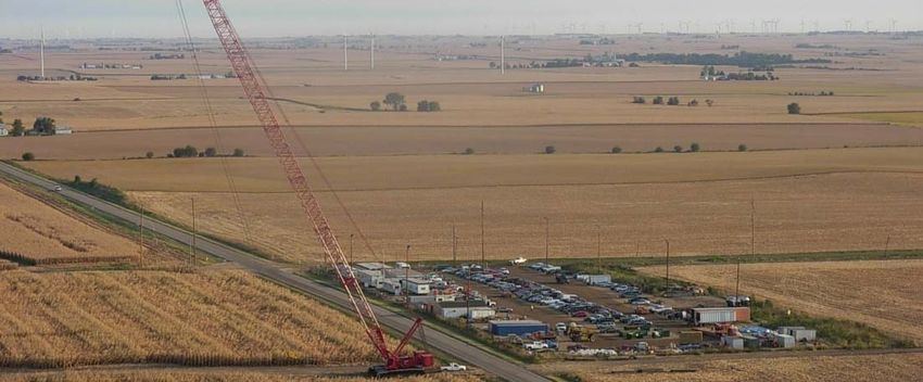
Plan of Development                                                                                                    Lava Ridge Wind Project

Table of Contents

        PROJECT DESCRIPTION.............................................................................................................. 1
  1.1      Introduction .................................................................................................................................. 1
  1.2      Purpose and Need for the Project ................................................................................................ 1
  1.3      General Facility Description, Design, and Operation .................................................................... 3
    1.3.1         Project Location, Land Ownership, and Jurisdiction ............................................................. 3
    1.3.2         Legal Land Description of Facility .......................................................................................... 3
    1.3.3         Total Acreage and General Dimensions ................................................................................ 3
    1.3.4         Number and Size of Wind Turbines ...................................................................................... 4
    1.3.5         Wind Turbine Configuration and Layout............................................................................... 6
    1.3.6         Substations and Transmission Lines ..................................................................................... 6
    1.3.7         Ancillary Facilities, Access Roads, Buildings, and Parking Areas ......................................... 18
    1.3.8         Temporary Construction Workspace, Yards, and Staging Areas ........................................ 19
    1.3.9         Water Usage, Amounts, and Sources ................................................................................. 19
    1.3.10        Erosion Control and Stormwater Drainage ......................................................................... 20
    1.3.11        Vegetation Treatment, Weed Management, and Any Proposed Use of Herbicides ......... 20
    1.3.12        Waste and Hazardous Materials Management .................................................................. 21
    1.3.13        Fire Protection..................................................................................................................... 21
    1.3.14        Site Security and Fencing .................................................................................................... 21
    1.3.15        Spill Prevention and Containment ...................................................................................... 21
  1.4      Alternatives Considered by Applicant ......................................................................................... 22
  1.5      Other Federal, State, and Local Agency Permit Requirements................................................... 22
  1.6      Financial and Technical Capability of Applicant .......................................................................... 24
        CONSTRUCTION OF FACILITIES ................................................................................................ 25
  2.1      Laydown/Staging Areas............................................................................................................... 25
  2.2      Geotechnical Studies................................................................................................................... 25
  2.3      Phased Projects, Approach to Construction and Operation ....................................................... 26
  2.4      Access and Transportation System, Component Delivery, and Worker Access ......................... 26
  2.5      Construction Work Force Numbers, Vehicles, Equipment, and Timeframes ............................. 26
  2.6      Site Preparation, Vegetation Removal, and Treatment .............................................................. 28
  2.7      Site Clearing, Grading, and Excavation ....................................................................................... 29

Magic Valley Energy, LLC                                                                                                                           Page i
Plan of Development                                                                                                       Lava Ridge Wind Project

  2.8       Gravel, Aggregate, and Concrete ................................................................................................ 30
  2.9       Wind Turbines ............................................................................................................................. 30
  2.10      Electrical ...................................................................................................................................... 38
  2.11      Aviation Lighting ......................................................................................................................... 47
  2.12      Site Stabilization, Protection, and Reclamation .......................................................................... 48
         Related Facilities and Systems ................................................................................................ 49
  3.1       Transmission System Interconnect ............................................................................................. 49
    3.1.1          Existing and Proposed Transmission System ...................................................................... 49
    3.1.2          Ancillary Facilities and Substations ..................................................................................... 49
    3.1.3          Status of Interconnect Agreement ..................................................................................... 49
  3.2       Meteorological Towers ............................................................................................................... 50
  3.3       Other Related Systems................................................................................................................ 50
         Operations and Maintenance ................................................................................................. 51
  4.1       Operation and Facility Maintenance Needs ............................................................................... 51
  4.2       Maintenance Activities ............................................................................................................... 52
  4.3       Operations Workforce, Equipment, and Ground Transportation .............................................. 53
         Environmental Considerations ................................................................................................ 55
  5.1       General Description of Site Characteristics and Potential Environmental Issues....................... 55
    5.1.1          Sensitive Species and Habitats ............................................................................................ 55
    5.1.2          Special Land Use Designations ............................................................................................ 55
    5.1.3          Visual Resource Management (“VRM”) Designations ........................................................ 56
    5.1.4          Cultural and Historic Resource Sites and Values ................................................................ 57
    5.1.5          Native American Tribal Considerations .............................................................................. 58
  5.2       Other Uses on Project Site .......................................................................................................... 58
    5.2.1          Aviation and/or Military Considerations............................................................................. 58
    5.2.2          Other Environmental Considerations ................................................................................. 60
  5.3       Design Criteria ............................................................................................................................. 60
         Maps ...................................................................................................................................... 61

Magic Valley Energy, LLC                                                                                                                              Page ii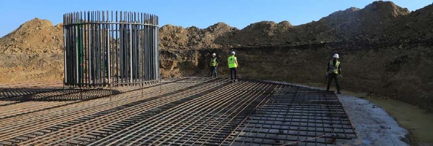
Plan of Development                                                     Lava Ridge Wind Project

Appendices

APPENDIX A             Site Plans

APPENDIX B             Legal Description

APPENDIX C             Alternatives Considered

APPENDIX D             Stormwater Pollution Prevention Plan

APPENDIX E             Reclamation Plan

APPENDIX F             Health and Safety Plan

APPENDIX G             Spill Prevention, Control, and Countermeasures Plan

APPENDIX H             Design Criteria

APPENDIX I             Blasting Plan Methodology

APPENDIX J             Road Design, Traffic, and Transportation Plan

APPENDIX K             Flagging, Fencing, and Signage Plan

APPENDIX L             Decommissioning Plan

APPENDIX M             Bird and Bat Conservation Stragety and Eagle Management Plan

APPENDIX N             Cultural Properties Treatment Plan

APPENDIX O             Dust and Emmissions Control Plan

APPENDIX P             Environmental Construction and Compliance Monitoring Plan

Magic Valley Energy, LLC                                                                Page iii
Plan of Development                                                                                                Lava Ridge Wind Project

Figures

Figure 1‐1: Typical Wind Turbine Sizes ......................................................................................................... 5
Figure 1‐2: Typical Distribution Line Dimensions (Collector Line) ................................................................ 7
Figure 1‐3: Typical Collector Line Structure .................................................................................................. 8
Figure 1‐4: Typical Collector Lines ................................................................................................................ 8
Figure 1‐5: Example Collector Substation ................................................................................................... 10
Figure 1‐6: Typical 230 kV Monopole Structure ......................................................................................... 11
Figure 1‐7: Typical 230 kV Monopole Angle Structure ............................................................................... 11
Figure 1‐8: Typical Substation Layout ......................................................................................................... 13
Figure 1‐9: Typical Lattice Guyed V Tangent Tower ................................................................................... 14
Figure 1‐10: Typical Tubular Guyed V Tangent Tower ................................................................................ 14
Figure 1‐11: Typical Single Circuit Lattice Self‐Supporting Tower .............................................................. 15
Figure 1‐12: Typical Single Circuit Monopole Self‐Supporting Tower ........................................................ 15
Figure 1‐13: Typical Self‐Supporting Tubular Angle/Crossing Tower ......................................................... 16
Figure 1‐14: Typical Single Circuit H‐Frame Tower ..................................................................................... 16
Figure 2‐1: Typical Construction Laydown Area ......................................................................................... 25
Figure 2‐2: Turbine Foundation Under Construction ................................................................................. 31
Figure 2‐3: Complete Turbine Mat.............................................................................................................. 32
Figure 2‐4: Backfilled Turbine Mat.............................................................................................................. 32
Figure 2‐5: Typical Unloading of Turbine Components .............................................................................. 33
Figure 2‐6: Crane Pad and Mats .................................................................................................................. 34
Figure 2‐7: Erected Base Tower Section ..................................................................................................... 34
Figure 2‐8: Mid Tower Section Placement .................................................................................................. 35
Figure 2‐9: Erection of Complete Rotor ...................................................................................................... 36
Figure 2‐10: Crane Lifting Blade to the Hub................................................................................................ 37
Figure 2‐11: Typical Trenching with Trenching Machine ............................................................................ 40
Figure 2‐12: Example Collection Substation ............................................................................................... 42
Figure 2‐13: Foundation Installation, Tower Assembly, and Tower Erection ............................................. 45
Figure 2‐14: Typical Transmission Line Conductor Stringing Activities ...................................................... 47
Figure 4‐1: Example O&M Building ............................................................................................................. 53

Tables

Table 1‐1: Project Components, Quantities, and Disturbance ..................................................................... 4
Table 1‐2: Minimum and Maximum Turbine Characteristics ....................................................................... 5
Table 1‐3: Federal, State, and Local Permits............................................................................................... 22

Magic Valley Energy, LLC                                                                                                                    Page iv
Plan of Development Lava Ridge Wind Project
1 PROJECT DESCRIPTION
2 1.1 Introduction
3 This Plan of Development (“POD”) is prepared in support of an application by Magic Valley Energy,
4 LLC (“MVE” or “the Proponent”) to the Bureau of Land Management (“BLM”) for authorization to
5 use federal lands for the construction, operation, maintenance, and decommissioning of an up to
6 400‐turbine wind energy generating facility and ancillary facilities. The proposed project will be
7 known as the “Lava Ridge Wind Project,” sometimes referred to herein as the “Project” or “Facility.”
8 The Project is located approximately 25 miles northeast of Twin Falls, Idaho in the BLM Shoshone
9 Field Office management area. The majority of lands required for Project implementation are
10 managed by BLM, with relatively fewer potential parcels that are state or privately owned.
11 The Facility will generally comprise of wind turbine generators, new and improved access roads,
12 electrical collector and transmission lines, onsite substations with associated components, fiber
13 optic communications equipment, interconnecting substation additions, battery energy storage
14 system, operations and maintenance facilities, temporary construction staging areas, batch plants,
15 and other ancillary facilities. The Project’s planned 500 kilovolt (“kV”) generation intertie may
16 interconnect at the existing Idaho Power Midpoint substation approximately seven miles south of
17 Shoshone, Idaho, or at an alternative location along the permitted but not yet constructed
18 Southwest Intertie Project – Northern Portion (“SWIP‐North”) (IDI‐26446).
19 MVE’s anticipated schedule for the Project includes: 1) an approximately two year development
20 period during which the applicable permits and approvals are sought, targeting completion of
21 development during the third calendar quarter of 2022; 2) an approximately two year construction
22 timeframe with initial commercial operations commencing during the fourth calendar quarter of
23 2024; and 3) an operations period of up to 30 years. The Project may be constructed in a phased
24 manner depending on MVE’s continued commercial analysis and the electrical market conditions at
25 the end of the development period.
26 1.2 Purpose and Need for the Project
27 MVE’s purpose for the Project is to reliably and economically produce renewable energy with wind
28 turbine generators for delivery to power markets in the western United States, including those
29 markets accessed via interconnection to the existing Midpoint Substation or to an alternative new
30 substation constructed along the permitted, but not yet constructed, Southwest Intertie Project –
31 Northern Portion. Construction and operation of the Project will:
32 provide a new economic and reliable renewable energy source;
33 have the ability to serve multiple power markets in the western United States, including
34 those accessible through use of the Southwest Intertie Project transmission corridor;
35 provide economic benefits to the State of Idaho, and the local counties of Jerome, Lincoln
36 and Minidoka, including the creation of new jobs;
Magic Valley Energy, LLC Page 1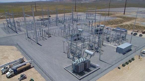
Plan of Development Lava Ridge Wind Project
1 contribute to the achievement of renewable energy and carbon reduction goals.
2 maximize the potential extraction of wind energy to make the resource economically
3 attractive to customers while balancing environmental sensitivities
4 The need for the Project arises from regulatory, utility, and consumer driven objectives to
5 incorporate increasing amounts of renewable/carbon free energy sources into energy supply
6 portfolios. Substantial amounts of new renewable energy resources are required to meet this need.
7 A majority of states in the western U.S. have specific renewable energy goals. These goals include:
8 Idaho Power Company: 100% clean energy goal by 2045
9 State of Nevada: 50% renewable supply by 2030; 100% carbon‐free by 2050
10 State of California: 50% renewable supply by 2025; 60% by 2030; 100% zero‐carbon supply
11 by 2045
12 State of Arizona: 15% renewable supply by 2025
13 State of Utah: 20% renewable supply by 2025
14 State of Oregon: 50% renewable supply by 2040
15 State of Washington: 100% carbon‐free by 2045
16 State of Montana: 15% renewable supply since 2015
17 State of New Mexico: 50% renewable supply by 2030, 100% carbon‐free supply by 2045
18 City of Los Angeles: 100% carbon‐free by 2045
19 If Idaho Power Company alone were to meet all of its clean energy goals with renewables it would
20 need over two thousand megawatts by 2045.
21 A recent joint California agency1 analysis anticipates that nearly 900 MW of new wind generation
22 needs to come online annually for the next 25 years in order to meet California’s clean energy goals.
23 For many western states, these clean energy goals are bold objectives that will require 10’s of
24 thousands of megawatts of incremental renewable energy resources to achieve these standards.
25 In addition, providing reliable electric supply that is increasingly sourced from renewable energy
26 will most likely require load serving entities to look beyond their immediate service territory to
27 provide locational diversity of renewable generators. Renewable supply portfolios with greater
28 locational diversity can hedge against localized weather conditions affecting their ability to provide
29 reliable service to their customers and help achieve a more economic portfolio of supply resources.
30 Existing and planned transmission pathways will enable the Project to deliver renewable energy to
31 load serving entities in many of the western states listed above.
1
California Energy Commission, California Public Utilities Commission, and the California Air Resources Board;
https://www.energy.ca.gov/event/workshop/2020‐12/notice‐senate‐bill‐100‐draft‐report‐workshop
Magic Valley Energy, LLC Page 2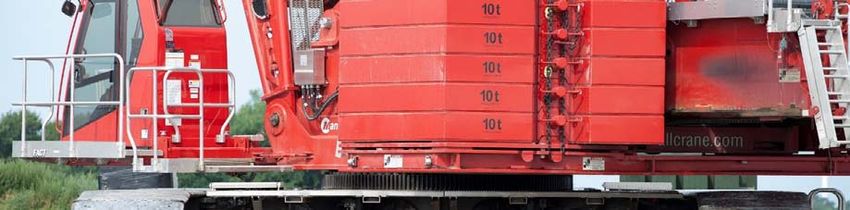
Plan of Development                                                              Lava Ridge Wind Project

 1        The proposed Project location was selected based on the quality of the wind resource in the area,
 2        the power markets accessible by existing and planned transmission lines in the area, the availability
 3        of suitable land, and the absence of land use constraints such as wildlife management areas, areas
 4        of critical environmental concern (“ACECs”), designated wilderness areas, wilderness study areas
 5        (“WSAs”), roadless areas, and other restrictive land use designations. Due to its location in relative
 6        proximity to existing population centers and infrastructure, the proposed siting of the Project will
 7        minimize environmental impacts and demands on local municipal services. Further, the Project will
 8        enhance the local economy by creating employment opportunities, tax revenues, and support of
 9        local businesses. Wind energy projects such as the proposed Project also help displace fossil‐fuel
10        electric generation with clean, renewable power, which reduces overall greenhouse gas (GHG)
11        emissions.

12        1.3       General Facility Description, Design, and Operation

13        1.3.1 Project Location, Land Ownership, and Jurisdiction
14        The Project will be located primarily on public lands managed by the BLM Shoshone Field Office
15        within the Idaho counties of Jerome, Lincoln, and Minidoka. Relative to the surrounding
16        communities, the general area for development is on open range land east of Shoshone, north of
17        Eden and Hazelton, and west of Minidoka. Dietrich is the closest community to the development
18        area. Siting of wind turbine strings will concentrate in the higher elevation lands associated with
19        several buttes in the Project area, with arrays of wind turbines located on mid‐elevation lands
20        between the buttes. The prominent buttes on the landscape within the development area include
21        Wilson Butte, Cinder Butte, Owinza Butte, Sid Butte, and Kimama Butte.

22        The vast majority of Project features will be located on BLM managed lands. Several State of Idaho
23        owned parcels are also present within the Project area and would provide opportunities to locate
24        additional wind turbines, collector and transmission lines, and potentially other ancillary features.
25        Tracts of privately owned parcels are adjacent to and interspersed within the development area.
26        MVE may approach select private landowners where efficiencies in design may be realized by
27        locating wind turbines or other Project features on those parcels.

28        1.3.2 Legal Land Description of Facility
29        A detailed legal land description of the Project area can be found in Appendix B.

30        1.3.3 Total Acreage and General Dimensions
31        Table 1‐1 provides a summary of the anticipated project components, long‐ and short‐term right‐
32        of‐way encumbrances, and associated disturbance acreages.

     Magic Valley Energy, LLC                                                                            Page 3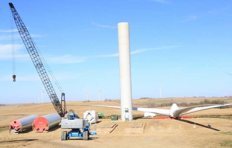
Plan of Development                                                                   Lava Ridge Wind Project

 1                               Table 1‐1: Project Components, Quantities, and Disturbance

                                                                                     Temporary        Permanent
                                                      Long‐Term     Short‐Term
      Project Component                                                              Disturbance      Disturbance
                                                     ROW (acres)    ROW (acres)
                                                                                        (acres)          (acres)
      Wind Turbines                                      2864            0              2545              319
      34.5 kV Collector System                           2611            0               399               20
      230 kV Transmission System                          538            0               173               18
      500 kV Transmission System                          576            0               133               26
      Permanent Access Roads                             1349            0               0                1349
      Temporary Road and Crane Disturbance               1689           284             1973               0
      Substations                                         101            26              26               101
      Battery Storage Facility                            40             5                5                40
      O&M Facilities                                      46             12              12                46
      Staging Yards and Batch Plants                      0             106              106               0
      ADLS                                                4              0                3                1
      Permanent Met Towers                                12             0               10                2

      TOTAL                                              9830           433             5385              1922
 2

 3           1.3.4 Number and Size of Wind Turbines
 4           Several factors influence the number and size of wind turbines for any given project and make it
 5           impractical to identify with certainty the exact characteristics of the turbine during the early
 6           development stage. Manufacturers’ advancement in turbine technology during the wind project
 7           development period can offer opportunities to deploy more efficient models that are better suited
 8           to the Project area’s wind resource. The ultimate selection of a specific turbine model is an iterative
 9           process that considers the wind resource, siting constraints, mitigation requirements, and the
10           timing of a specific turbine’s availability in relation to the construction schedule. While the specific
11           turbine model and its associated size characteristics will not be known until late in the development
12           phase, MVE is able to define the anticipated range of potential wind turbine units that may be sited
13           within the Project including the number of units as well as a range of key sizing characteristics.

14           A wind turbine typically consists of three main components: the nacelle, tower, and rotor blades.
15           The nacelle houses the generator, gearbox, and (in some cases) the transformer while supporting
16           the rotor and blades at the hub. The turbine tower supports and provides access to the nacelle.
17           MVE expects the turbine hub will be between 260 and 460 feet above the ground, depending on
18           the turbine model selected. The turbine blades would extend between 130 and 280 feet from the
19           hub, meaning a rotor diameter between 260 and 560 feet and a rotor “swept area” between 53,100
20           and 246,400 square feet. When a blade is in‐line with the tower, the maximum height will be
21           between 390 and 740 feet. Refer to Figure 1‐1 for a drawing showing these typical wind turbine
22           sizes.

     Magic Valley Energy, LLC                                                                                   Page 4
Plan of Development                                                               Lava Ridge Wind Project

 1                         Table 1‐2: Minimum and Maximum Turbine Characteristics

                  Characteristic                    Minimum                  Maximum
                  Hub Height (ft.)                     260                          460
                  Rotor Diameter (ft.)                 260                          560
                  Rotor Swept Area (sq. ft.)          53,100                      246,400
                  Total Height (ft.)                   390                          740

 2
 3                                       Figure 1‐1: Typical Wind Turbine Sizes

 4        The generating capacity of a specific turbine often closely correlates with its size. Turbine models
 5        with a relatively higher generating capacity tend to be taller with larger rotor swept areas. To
 6        achieve the intended overall Project generating capacity, a larger number of smaller individual
 7        turbines may deployed, or a smaller number of larger turbines may be deployed, or a mix of small
 8        and large turbines may be deployed based on turbine selection factors mentioned above.

 9        MVE is proposing up to 400 total wind turbine generators for the Project. The total generating
10        capacity of the Project would then depend on the individual capacity ratings of the turbine models

     Magic Valley Energy, LLC                                                                          Page 5
Plan of Development Lava Ridge Wind Project
1 selected for the Project. As an example, if a turbine model with a 3‐megawatt (MW) generating
2 capacity is determined to be best suited for the Project, constructing 400 of those individual
3 turbines would equate to a 1,200 MW project. If a turbine model with a 4 MW generating capacity
4 is ideal for the Project, 400 of those individual turbines would equate to a 1,600 MW project. As
5 siting constraints, turbine technology and availability, and other factors listed above become
6 refined during the development phase, MVE will be able to narrow the options for ultimate
7 deployment.
8 1.3.5 Wind Turbine Configuration and Layout
9 MVE is proposing up to 400 individual turbines across the Project area to achieve the desired
10 capacity of the Project. The turbines will be situated in rows (referred to as a “string” or “array” of
11 turbines) that are expected to generally be in a north‐south orientation based on the local prevailing
12 wind direction. The separation between individual turbines within a given string and the distance
13 between the strings themselves will be dependent on the size of turbine selected and other siting
14 considerations. A preliminary turbine configuration and layout within the Project area is provided
15 in Figure 6‐1. This preliminary layout only considers placement of turbines on BLM managed and
16 State lands. Turbine locations on neighboring private lands may be considered if mutually agreed
17 to with the property owners.
18 The preliminary turbine locations have been proposed within ½ mile‐wide siting corridors to allow
19 for the flexibility to microsite individual turbines based on site‐specific engineering or resource
20 constraints. In addition to the proposed siting corridors, MVE has identified alternative turbine
21 siting corridors to accommodate the relocation of turbines from the proposed corridors, at MVE’s
22 discretion. Should MVE identify an engineering issue within the proposed corridors, or determine
23 that relocating proposed turbines from a proposed to an alternative corridor will increase project
24 efficiency, MVE may elect to make that adjustment. These siting corridors are represented in
25 Figures 6‐1 and 6‐2, as well as on the Site Plans in Appendix A.
26 Siting corridors for supporting Project infrastructure (i.e. roads and collector system) have been
27 proposed in a similar manner on the above‐reference Project maps. Access roads and collector
28 systems in alternative siting corridors would only be utilized should there be a relocation of turbines
29 to the associated corridor. In most cases, this would translate to a reduction in access roads and
30 collector lines from the Project corridor where turbines were removed.
31 1.3.6 Substations and Transmission Lines
32 Collector Lines: Each wind turbine will be connected to a system of overhead or underground
33 electrical collector lines, typically designed to operate at 34.5 kV. Individual collector lines will run
34 from turbine site to turbine site, and after connecting the optimum number of generators the line
35 will proceed to a collector substation. The structures of the collector lines may be wood, steel, or
36 concrete poles that are 60 – 90 feet tall and spaced 300 – 350 feet apart, depending on terrain.
Magic Valley Energy, LLC Page 6Plan of Development Lava Ridge Wind Project
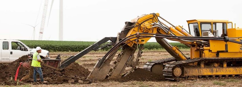
1 Refer to Figure 1‐2 for dimensions of a typical collector line and Figure 1‐3 and Figure 1‐4 for photos
2 of a typical collector line. Preliminary routes of these collector lines are provided in Figure 6‐1.
3
4 Figure 1‐2: Typical Distribution Line Dimensions (Collector Line)
Magic Valley Energy, LLC Page 7Plan of Development Lava Ridge Wind Project
1
2 Figure 1‐3: Typical Collector Line Structure
3
4 Figure 1‐4: Typical Collector Lines
Magic Valley Energy, LLC Page 8Plan of Development Lava Ridge Wind Project
1 Junction Boxes: For long runs of underground cable, it will be beneficial to utilize a junction box in
2 order to join segments together for a single circuit. Junction boxes are utilized to allow for ease of
3 operations and maintenance in the event of a failure, and to allow for proper acceptance testing
4 during installation. Junction boxes are typically located alongside an access road to allow for easy
5 access. Similarly, at points in the underground portion of the collection system where the circuit
6 needs to “branch” off in different directions to connect turbines, a three‐way or four‐way junction
7 box is utilized to allow for efficient use of underground cable while lessening the overall
8 disturbance.
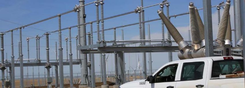
9 Collector Substations: Up to five (5) 34.5 /230 kV collector substations will be located throughout
10 the Project area to aggregate individual collector lines from turbine strings in the vicinity and
11 increase the voltage to 230 kV. The collector substations will include electrical equipment such as
12 transformers, medium‐voltage and high‐voltage circuit breakers, capacitor banks, electrical bus
13 work, meters, disconnect switches and an electrical control house. Lightning arresters, overhead
14 shield wires, and lightning masts will be installed in the substation to protect against over‐voltages
15 caused by lightning strikes. While final engineering will determine the exact components and
16 placement within the substation, it is likely that that highest structure will not exceed 75 feet in
17 height. Instrument transformers, relays, and a communication network will be used to detect,
18 isolate and clear electrical faults as soon as practical to ensure the safety of equipment, personnel,
19 and the public. Protective relaying will meet Institute of Electrical and Electronic Engineers (IEEE)
20 requirements and will be coordinated with grid protection to ensure system reliability and safety is
21 maintained.
22 Due to the size of the Project, the final design may utilize different size substations. For example, a
23 large cluster of turbines may connect to a larger three‐transformer substation, where a smaller
24 cluster of turbines would connect to a smaller single‐transformer substation. However, in order to
25 minimize overall disturbance and provide a more efficient electrical design, MVE may elect to build
26 multiple medium‐sized substations as opposed to a single large substation in each area. See Figure
27 1‐5 below for an example collector substation.
Magic Valley Energy, LLC Page 9Plan of Development Lava Ridge Wind Project
1
2 Figure 1‐5: Example Collector Substation
3 230 kV Transmission Lines: A series of 230 kV overhead transmission lines will connect the collector
4 substations to one larger substation where the voltage will be increased to 500 kV. The 230 kV
5 transmission lines will parallel existing facilities and infrastructure to the extent practical in an effort
6 to consolidate utility lines across the landscape. The 230 kV transmission lines may utilize single or
7 double circuit lattice, H‐Frame, or tubular monopole type structures that are comprised of angular
8 steel, tubular steel, corten steel, concrete, wood, or a hybrid. The structure heights may range from
9 70 to 130 feet, and the average structure span may range from 400 to 1,000 feet. Examples of
10 typical structure types and dimensions are provided in Figure 1‐6 and Figure 1‐7. The selection of
11 specific tower type, height, and placement will be determined during the final design of the project,
12 taking into account any physical constraints, results of electrical studies, National Electric Safety
13 Code Standards, and applicable environmental factors.
Magic Valley Energy, LLC Page 10Plan of Development Lava Ridge Wind Project
1
2 Figure 1‐6: Typical 230 kV Monopole Structure
3
4 Figure 1‐7: Typical 230 kV Monopole Angle Structure
5 The 230 kV transmission lines may be supported by concrete foundations, pre‐cast concrete
6 footings, direct‐embedded structure segments, and may require the use of guy cables that are
Magic Valley Energy, LLC Page 11Plan of Development Lava Ridge Wind Project
1 anchored to the ground. The structures will support three (3) phases of conductor per circuit,
2 spaced 10 to 20 feet apart depending on structure type. Insulators and associated hardware will be
3 used to position and support the conductor while maintaining electrical design clearances between
4 the conductors and the structure. The structures will also support two (2) overhead ground wires
5 at the top of the structures to protect the system from lightning strikes. One of the overhead
6 ground wires may incorporate a fiber optic component that could be used for voice and data
7 communication, protective relay telemetering, and for supervisory control and data acquisition.
8 230/500 kV Substation: The Project will include a single 230/500 kV substation that will aggregate
9 the 230 kV transmission lines from the collector substations and increase the voltage to 500 kV.
10 Similar to the collector substations, the 230/500 kV substation will include equipment such as
11 transformers, high‐voltage circuit breakers, capacitor banks, electrical bus work, meters, disconnect
12 switches and an electrical control house. Lightning arresters, overhead shield wires, and lightning
13 masts will be installed in the substation to protect against over‐voltages caused by lightning strikes.
14 Instrument transformers, relays, and a communication network will be used to detect, isolate and
15 clear electrical faults as soon as practical to ensure the safety of equipment, personnel, and the
16 public. Protective relaying will meet Institute of Electrical and Electronic Engineers (IEEE)
17 requirements and will be coordinated with grid protection to ensure system reliability and safety is
18 maintained. Refer to Figure 6‐1 for the preliminary location of the 230/500 kV substation, and
19 Figure 1‐8 for a schematic drawing of typical substation components.
20 Typically, substations will have battery backups for redundancy of protection systems. The 230/500
21 kV substation may have diesel or propane backup generators. Backup generators are only intended
22 to run during unplanned outage scenarios and predetermined operation cycles to confirm proper
23 function. These occurrences are anticipated to be infrequent, short‐duration activities with minimal
24 noise impacts.
Magic Valley Energy, LLC Page 12Plan of Development Lava Ridge Wind Project
1
2 Figure 1‐8: Typical Substation Layout
3 500 kV transmission line: An overhead 500 kV transmission line will connect the 230/500 kV
4 substation to the Project’s point of interconnection at Midpoint Substation or an alternative
5 location along the SWIP‐North alignment. The 500 kV transmission line will parallel existing facilities
6 and infrastructure to the extent practical in an effort to consolidate utility lines across the
7 landscape. Several types of transmission structures may be used for the 500 kV transmission line.
8 The towers may be tubular steel guyed‐V, lattice steel guyed‐V, and self‐supporting steel lattice,
9 poles, and H‐frame structures. The structures will be made of unpainted galvanized or Corten steel.
10 The proposed tower configurations and typical heights are illustrated in Figures 1‐9 through 1‐14.
11 Tower‐to‐tower span lengths will be dependent upon terrain and siting obstacles within or near the
12 ROW, and will typically be 1,000 to 1,600 feet.
Magic Valley Energy, LLC Page 13Plan of Development Lava Ridge Wind Project
1
2 Figure 1‐9: Typical Lattice Guyed V Tangent Tower
3
4 Figure 1‐10: Typical Tubular Guyed V Tangent Tower
Magic Valley Energy, LLC Page 14Plan of Development Lava Ridge Wind Project
1
2 Figure 1‐11: Typical Single Circuit Lattice Self‐Supporting Tower
3
4 Figure 1‐12: Typical Single Circuit Monopole Self‐Supporting Tower
Magic Valley Energy, LLC Page 15Plan of Development Lava Ridge Wind Project
1
2 Figure 1‐13: Typical Self‐Supporting Tubular Angle/Crossing Tower
3
4 Figure 1‐14: Typical Single Circuit H‐Frame Tower
Magic Valley Energy, LLC Page 16Plan of Development Lava Ridge Wind Project
1 Guyed‐V transmission structures will either be tubular or lattice steel with four supporting guy
2 anchors. The foundation for the guyed‐V structures will be precast spread footings or concrete
3 drilled piers. The precast footings will be approximately 6.5 feet square and 4.75 feet deep. The
4 concrete drilled piers will be approximately 4 feet in diameter and range from 8 to 30 feet in depth.
5 Each guy anchor will be a grouted earth anchor, with a diameter of less than a foot and ranging in
6 depth from 10 to 60 feet. The grout used with the anchors is similar to concrete. Guy anchors may
7 alternatively consist of concrete drilled piers that are approximately 2 – 4 feet in diameter and 8 to
8 20 feet in depth
9 Self‐supporting steel‐lattice transmission structures will require four footings. The foundations for
10 the steel‐lattice towers will be cast‐in‐place concrete approximately 3 to 5 feet in diameter with a
11 15‐ to 20‐foot depth.
12 Self‐supporting steel pole transmission structures (three single poles for turning structures, as
13 illustrated on Figure 1‐7) have three poles and require one footing for each pole. H‐frame structures
14 (as illustrated on Figure 1‐14) require two footings. Self‐supporting tubular‐steel structures will be
15 installed on a single pier with anchor‐bolt foundations or directly imbedded into the foundation.
16 Foundations for these structures will typically be 6 to 10 feet in diameter and 25 to 55 feet in depth.
17 The conductor for the 500 kV circuit would consist of three phases, with a three‐conductor bundle
18 for each phase. Spacing between subconductors in a bundle would be approximately 18 inches.
19 Aluminum‐trapezoidal or aluminum‐stranded nonspecular conductors with a steel‐stranded
20 reinforced core would be used. The aluminum carries the majority of the electrical current, and the
21 steel provides tensile strength to support the aluminum strands. Minimum conductor height above
22 the ground for the 500 kV lines would be 31 feet at 212 degrees Fahrenheit in accordance with the
23 National Electric Safety Code (“NESC”). The exact height of each tower would be governed by
24 topography and safety requirements for conductor clearance. Alternate materials or designs may
25 be selected to optimize efficiency, reliability, and/or economics.
26 Three assemblies of insulators in the form of a “V” or “I” would be used to position and support
27 each of the conductor bundles, while maintaining electrical design clearances between the
28 conductors and the tower. Typically, “V” form insulators will be used for typical 500 kV tangent
29 tower structures, while “I” form insulators will be used for 500 kV dead‐end tower structures. Some
30 towers may use a combination of both insulator forms.
31 To protect the 500 kV transmission line from direct lightning strikes, two overhead ground wires,
32 approximately ½‐inch in diameter, would be installed on the top of the structures. It is likely that a
33 fiber optic line will be integrated with one of these overhead ground wires. Current from lightning
34 strikes would be transferred through the ground wires and structures into the ground.
35 Ground rods will be installed next to the structure foundations to prevent a lightning strike from
36 damaging the overhead conductors. After the ground rods have been installed, the grounding will
37 be tested to determine the resistance to ground. If the measurements indicate a high resistance,
38 counterpoise will be installed, which will consist of trenching in‐ground wire with a ground rod
Magic Valley Energy, LLC Page 17Plan of Development Lava Ridge Wind Project
1 driven at the end. The counterpoise will be contained within the limits of the transmission line or
2 adjacent access road right‐of‐way, and may be altered or doubled back‐and‐forth to meet the
3 requirements of the Project.
4 Interconnecting Substation: The 500 kV transmission line will interconnect with the existing
5 Midpoint Substation operated by Idaho Power Company or an alternative new switchyard located
6 along the SWIP‐North alignment. The interconnection of the Project to the existing substation will
7 require the addition of facilities such as addition of circuit breakers, busing, motor operated
8 disconnect switches, additional relay panels in the existing control enclosures, various auxiliary
9 substation equipment, and other electrical equipment. The scope of the additional equipment
10 required for interconnection will be determined through electrical system impact and facilities
11 studies. Interconnection of the Project to an alternative new switchyard along the SWIP‐North
12 alignment would require the construction of a facility similar to the 230/500 kV substation depicted
13 in Figure 1‐8, minus the voltage transformers.
14 Battery Energy Storage System: MVE is proposing to incorporate a battery energy storage system
15 adjacent to an onsite project substation. The storage system will consist of racks of electrochemical
16 batteries in a warehouse type building (resembling a data center; approximately 30 feet tall), AC/DC
17 power conversion and electrical control equipment, electrical distribution and transmission
18 facilities, communications equipment, operations and maintenance facilities, and other ancillary
19 facilities. These facilities would encumber approximately up to 40 acres adjacent to the onsite
20 230/500 kV substation. The capacity of the battery energy storage system will be determined in
21 the final design phase, once a specific turbine is selected and commercial contracts for Project
22 power are finalized. Forty acres will support the deployment of a battery energy storage system
23 with thousands of megawatt‐hours of storage potential.
24 1.3.7 Ancillary Facilities, Access Roads, Buildings, and Parking Areas
25 Access Roads: See the Road Design, Traffic and Transportation Plan attached as Appendix J to the
26 POD.
27 Communication Facilities: A high‐speed communication system is required for operation of the wind
28 turbines, substations, transmission lines, battery energy storage system, and other Project facilities.
29 Fiber optic lines will provide the primary communication pathway throughout the Project, and will
30 most often be incorporated into the design of the collector and transmission lines. These
31 communication pathways will be used for voice and data communication, protective relay
32 telemetering, and supervisory control and data acquisition. While MVE is not seeking to conduct or
33 lease commercial telecommunication services at this time, the system will be designed to
34 accommodate such requests. A redundant communications method may also be employed using
35 microwave systems.
36 Operations and Maintenance (O&M) Buildings: The Project will include one or more O&M buildings
37 to serve as office space, operations center, and maintenance shops/warehouses. The office portion
Magic Valley Energy, LLC Page 18Plan of Development Lava Ridge Wind Project
1 of the building will house facility staff and include facilities common to a business office such as a
2 conference room, offices, break room, and restrooms. A control room, where facility staff monitor
3 and control operation of the facility will also be located in this building. The facilities will also include
4 maintenance shops and warehouses where staff can bring equipment for testing, repairs or
5 maintenance.
6 Common ancillary features for the O&M facilities include staff parking areas, distribution power
7 source, potable water source such as an onsite well or water line to an existing water source, septic
8 system, and communication facilities. O&M staff necessary to operate the Project typically access
9 the O&M facilities daily. Additional information can be found in Section 4.3.
10 Intermodal Yard: Given the proximity of the Union Pacific rail line to the Project area, efficiencies
11 in turbine component delivery could be realized by transporting these parts to the Project via rail.
12 A number of existing sidings in the Project vicinity are being explored for use as intermodal yards
13 where components delivered by rail are transferred to semi‐trailers to complete the delivery to a
14 construction staging yard or individual work area.
15 Meteorological Towers: Multiple permanent meteorological towers will be placed in the Project
16 area to monitor the weather conditions and inform efficient operation of the wind turbines.
17 Additional information can be found in Section 3.2.
18 1.3.8 Temporary Construction Workspace, Yards, and Staging Areas
19 Secure laydown and construction staging areas (up to 50 acres per area) will be established in the
20 vicinity of the Project area as necessary to support construction logistics and activities. These areas
21 will be used to receive and stage Project components and construction equipment, and serve as an
22 assembling location for construction workers. The areas will include temporary construction offices
23 and support facilities such as a portable toilet trailer and a portable amenities trailer. These
24 temporary construction areas may also serve as the location of mobile concrete batch plants.
25 The location of the proposed staging areas will be strategically selected in an effort to avoid
26 environmentally and culturally sensitive areas. Previously developed sites on non‐federal lands in
27 the Project vicinity may be considered as well. The temporary construction areas will be established
28 in areas that are relatively flat and close to a primary access point for the Project. This would provide
29 efficient access for materials and equipment being delivered to the staging area and disbursement
30 to the active work sites.
31 1.3.9 Water Usage, Amounts, and Sources
32 Water will be needed for dust control, batching water for concrete production, and other washing
33 needs (such as washing trucks, hydrating aggregate, etc.).
Magic Valley Energy, LLC Page 19Plan of Development Lava Ridge Wind Project
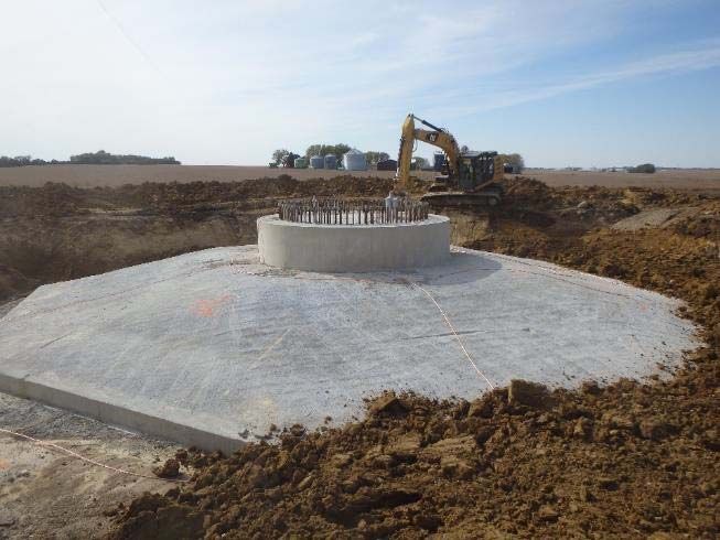
1 MVE estimates for civil scopes – including hydration/compaction, backfill, cement stabilization, and
2 dust control – that around 60‐90 million gallons of water will be required. In addition to the civil
3 scopes, MVE expects to use approximately 36 gallons of water per yard of concrete that is batched
4 for the wind turbine foundations. This equates to approximately 21,600 gallons of water per wind
5 turbine foundation. The actual amount of water utilized during construction will depend on final
6 design.
7 The water needs for the Project are expected to be served through a combination of existing
8 commercial sources and new groundwater wells. Up to six (6) new groundwater wells are
9 anticipated to support construction activities, four (4) of which may remain active to support
10 operation and maintenance of the Project. The new groundwater wells will be located within or in
11 close proximity to the proposed laydown yards and O&M facilities. Water will be stored in onsite
12 tanks or ponds in sufficient quantities to support usage rates during peak periods. Water quality
13 will determine the need for associated water treatment equipment to support potable use during
14 the operations phase.
15 Water may also be trucked into the Project area from commercial sources in the region. Potential
16 sources include canal companies, adjacent landowners, municipalities, or other commercial
17 sources.
18 During construction, mobile water tank stands, frac tanks, or similar water storage devices may be
19 strategically deployed throughout the project area to support proximate construction activities.
20 Above or belowground water lines may also be deployed adjacent to access roads to assist with the
21 conveyance of water to strategist use points. Select locations of water storage tanks and water
22 lines placed adjacent to roads may be maintained throughout the operations period to assist with
23 ongoing road maintenance, provide water access points to serve as a resource for potential wildland
24 fire suppression activities (refilling rangeland firetrucks or helicopter dip‐tanks), and potentially
25 offer value as a supplemental water source to mitigate potential impacts to public land grazing
26 operations.
27 1.3.10 Erosion Control and Stormwater Drainage
28 Prior to construction, a Storm Water Pollution Prevention Plan (“SWPPP”) will be developed for
29 implementation during construction. The SWPPP would include structural and non‐structural best
30 management practices (“BMP’s”) for erosion and sediment control as well as a monitoring and
31 corrective action plans, as necessary.
32 1.3.11 Vegetation Treatment, Weed Management, and Any Proposed Use of
33 Herbicides
34 A vegetation treatment and weed management plan, including any proposed use of herbicides will
35 be fully described in the Final Plan of Development and incorporate any mitigation measures
36 prescribed as a result of the environmental review process.
Magic Valley Energy, LLC Page 20Plan of Development Lava Ridge Wind Project
1 1.3.12 Waste and Hazardous Materials Management
2 See the Hazardous Materials Management Plan within Appendix F (Health and Safety Plan) of the
3 POD.
4 1.3.13 Fire Protection
5 See the Fire Protection and Prevention Plan within Appendix F (Health and Safety Plan) of the POD.
6 1.3.14 Site Security and Fencing
7 MVE will post safety and warning signs informing the public of construction activities where roads
8 enter the Project area from a public road. During construction, general public access to active work
9 zones will be monitored and controlled to prevent public access during such times when it would
10 not be safe for public on‐road or off‐road use. If theft or vandalism becomes an issue during non‐
11 construction hours, a security guard will patrol the Project area to prevent or minimize the threat
12 of those incidents.
13 Restricted access will be limited to short durations on access roads, or longer durations at discrete
14 work areas. Examples of a short‐term road access restriction includes during the transport of
15 oversize loads, blasting activities, turbine erection activities near existing roads, and during the
16 stringing of electrical conductor across or above roadways. Examples of longer duration access
17 restrictions include work areas with open trenches or excavations, and laydown yards. These types
18 of access restrictions will be coordinated with existing authorized right‐holders within the Project
19 area.
20 Gates to fenced areas, including the substations, switchyard, select lay down yards, and O&M area,
21 will be locked at night or during non‐construction hours. Gates or cattle guards will be installed
22 where openings are needed along range fences. Temporary warning fences or barricades (consisting
23 of warning tape, barricades, plastic mesh, and/or warning signs) will be erected in areas where
24 public safety risks could exist and where site personnel would not be available to control public
25 access (such as excavated foundation holes and electrical collection system trenches). Fences may
26 be installed around laydown areas, areas deemed hazardous, or areas where security or theft are
27 of concern, and would be removed at the completion of the construction period. A permanent
28 chain‐link fence will be installed around the Project O&M facilities and substations for safety.
29 Temporary fencing around unfinished turbine bases will be designed to warn people of the potential
30 danger. Excavations will be fenced with high visibility plastic mesh.
31 1.3.15 Spill Prevention and Containment
32 See the Spill Prevention, Containment, and Control Plan (“SPCC”) attached as Appendix G to the
33 POD.
Magic Valley Energy, LLC Page 21Plan of Development Lava Ridge Wind Project
1 1.4 Alternatives Considered by Applicant
2 See Alternatives Considered attached as Appendix C to the POD.
3 1.5 Other Federal, State, and Local Agency Permit Requirements
4 Table 1‐3: Federal, State, and Local Permits
Accepting Authority/
Action Requiring Permit, Approving/Consulting
Approval, or Review Permit/Approval Agency Statutory/Regulatory Reference
FEDERAL
Right‐of‐Way over Land Right‐of‐Way Grant BLM Federal Land Policy and
Under Federal Management Management Act (FLPMA) 43 USC
1761‐1771 and 43 CFR Part 2800
NEPA Compliance to Grant Environmental BLM National Environmental Policy Act
Right‐of‐Way Assessment or (NEPA), 42 USC 4321‐4327,
Environmental Impact Council on Environmental Quality
Statement (CEQ) 40 CFR Part 1500
BLM Grant of Right‐of‐Way National Historic Idaho State Historic National Historic Preservation Act
Preservation Act Preservation Office of 1966 (NHPA), 16 USC 47
Compliance (Section 106), 36 CFR Part 800,
Impact to Bald or Golden Eagle Take Permit U.S. Fish and Wildlife Bald and Golden Eagle Act, 16 USC
Eagles Service (USFWS) 668 et seq
Dredge or fill activities in Clean Water Act U.S. Army Corps of Clean Water Act, 33 USC 1344
waters of the United States Section 404 Permit Engineers (ACOE) (Section 404)
Any construction exceeding FAA Determination Federal Aviation 14 CFR Part 77
200 feet above ground level Administration (FAA)
STATE OF IDAHO
Operation of a Concrete Permit to Construct Idaho Department of IDAPA 50.01.01
Batch Plant Environmental Quality
Impacts to water quality 401 Water Idaho Department of 33 USC 1344
associated with discharges of Quality Certification, Environmental Quality
dredged or fill materials in Clean Water Act
waters of the United States
Magic Valley Energy, LLC Page 22Plan of Development Lava Ridge Wind Project
Accepting Authority/
Action Requiring Permit, Approving/Consulting
Approval, or Review Permit/Approval Agency Statutory/Regulatory Reference
Construction activities that Compliance with Idaho Department of 40 CFR Section 122.26(b)(14);
result in the discharge of Stormwater General Environmental Quality IDAPA 58.01.25
stormwater Permit
Crossing state or U.S. Encroachment Permit Idaho Department of IDAPA 39.03.42
highways Transportation (IDT)
Oversize / overweight loads Oversize / overweight Idaho Department of IDAPA 39.03.04; IDAPA 39.04.05;
Permit Transportation (IDT) IDAPA 39.03.06
Right‐of‐way or easement on Right‐of‐Way or Idaho Department of I.C. Sec. 58‐603; IDAPA 20.03.08
State Lands Easement Lands
LOCAL
Construction of Building Building Permit Jerome County Jerome County Code
Construction of Building Building Permit Lincoln County Lincoln County Code
Construction of Building Building Permit Minidoka County Minidoka County Code
Crossing of Highway District License or Permit to Jerome Highway District I.C. Sec 40‐1310
Roadway Cross Road
Easements or Rights‐
of‐Way
Crossing of Highway District License or Permit to Shoshone Highway I.C. Sec 40‐1310
Roadway Cross Road District #2
Easements or Rights‐
of‐Way
Crossing of Highway District License or Permit to Dietrich Highway District I.C. Sec 40‐1310
Roadway Cross Road
Easements or Rights‐
of‐Way
Crossing of Highway District License or Permit to Minidoka Highway I.C. Sec 40‐1310
Roadway Cross Road District
Easements or Rights‐
of‐Way
Magic Valley Energy, LLC Page 23You can also read