ROBUST BEAMFORMING BASED ON GRAPH ATTENTION NETWORKS FOR IRS-ASSISTED SATELLITE IOT COMMUNICATIONS
←
→
Page content transcription
If your browser does not render page correctly, please read the page content below
Preprints (www.preprints.org) | NOT PEER-REVIEWED | Posted: 31 January 2022                           doi:10.20944/preprints202201.0452.v1

     Article

     Robust beamforming based on graph attention networks for
     IRS-assisted Satellite IoT Communications
     Hailin Cao 1,*, Wang Zhu 1, Wenjuan Feng 1, Jin Fan 2

                                       1 Chongqing Key Laboratory of Space Information Network and Intelligent Information Fusion, Chongqing
                                         University, Chongqing 400044, China; hailincao@cqu.edu.cn; zhuwang1224@cqu.edu.cn;
                                         20173581@.cqu.edu.cn
                                       2 National Astronomy Observatory of China, Chinese Academy of Sciences, Beijing 100012, China;

                                         jfan@bao.ac.cn
                                       * Correspondence: hailincao@cqu.edu.cn

                                       Abstract: Satellite communication is expected to play a vital role in realizing Internet of Remote
                                       Things (IoRT) applications. This article considers an intelligent reflecting surface (IRS)-assisted
                                       downlink low Earth orbit (LEO) satellite communication network, where IRS provides additional
                                       reflective links to enhance the intended signal power. We aim to maximize the sum-rate of all the
                                       terrestrial users by jointly optimizing the satellite’s precoding matrix and IRS’s phase shifts. How-
                                       ever, it is difficult to directly acquire the instantaneous channel state information (CSI) and optimal
                                       phase shifts of IRS due to the high mobility of LEO and the passive nature of reflective elements.
                                       Moreover, most conventional solution algorithms suffer from high computational complexity and
                                       are not applicable to these dynamic scenarios. A robust beamforming design based on graph atten-
                                       tion networks (RBF-GAT) is proposed to establish a direct mapping from the received pilots and
                                       dynamic network topology to the satellite and IRS’s beamforming, which is trained offline using the
                                       unsupervised learning approach. The simulation results corroborate that the proposed RBF-GAT
                                       can achieve approximate performance compared to the upper bound with low complexity.

                                       Keywords: intelligent reflecting surface; low Earth orbit satellite; graph attention networks; unsu-
                                       pervised learning; beamforming

                                       1. Introduction
                                             With the advantages of providing global-coverage, high-throughput capability, and
                                       low-cost internet access, satellite communication has drawn significant attention from
                                       both industry and academia and is regarded as a promising solution for meeting the needs
                                       of the Internet of Remote Things (IoRT) [1,2]. Currently, there are three types of satellites
                                       in space that provide global service, including geosynchronous Earth orbit (GEO) satel-
                                       lites, medium Earth orbit (MEO) satellites and low Earth orbit (LEO) satellites [3]. Com-
                                       pared with GEO and MEO satellites, LEO satellites have recently become popular due to
                                       their lower development costs, better signal strength, and the potential for large-scale
                                       LEO satellite networks that can guarantee lower transmission delays [4,5]. More than 40
                                       000 LEO satellites are planned by SpaceX Starlink alone. On the other hand, LEO satellites
                                       are deployed at an altitude of 500–1500 km with an orbital period shorter than 2 hours.
                                       The fast movement of LEO satellites results in a very limited window for transmission to
                                       ground devices, approximately 10 min/pass [6]. As the amount of data transferred contin-
                                       ues to grow, it is a huge challenge for the LEO satellite to complete all transmission tasks
                                       within such a limited transmission window, especially when transmitting to remote rural
                                       areas lacking terrestrial infrastructure. The maximum completion time optimization for
                                       the Internet of Things (IoT) in LEO satellite-terrestrial integrated networks (STINs) was
                                       investigated in [7], and a cooperative nonorthogonal multiple access (NOMA) scheme for
                                       data transmission was proposed. Moreover, in practical satellite systems, line-of-sight
                                       (LoS) communication between satellite and terrestrial users is difficult to maintain due to

               © 2022 by the author(s). Distributed under a Creative Commons CC BY license.
Preprints (www.preprints.org) | NOT PEER-REVIEWED | Posted: 31 January 2022               doi:10.20944/preprints202201.0452.v1

                                 obstacles and shadowing [8]. In [9], the authors investigated unmanned aerial vehicle
                                 (UAV) swarms and LEO satellite constellation-assisted data collection for IoRT networks,
                                 where UAV swarms were used as relays to improve the channel environment. UAVs have
                                 the benefits of high mobility, flexible deployment, and LoS transmission [10,11]. However,
                                 when introducing UAVs in LEO-assisted IoRT networks, data transmission becomes more
                                 challenging because of the different channel characteristics of UAV-ground and UAV-sat-
                                 ellite links, as well as the battery and cache capacity limitations of UAVs.
                                       Considered promising technology, intelligent reflecting surfaces (IRSs) have recently
                                 received substantial attention [12-16]. IRS consists of a large number of passive elements
                                 which can introduce controllable phase shifts. Intelligently adjusting these phases can
                                 change the reflected signal propagation. Therefore, it has been widely deployed in wire-
                                 less communication systems to enhance the intended signal power at the receiver or mit-
                                 igate the cochannel interference [14-16]. [14] and [15] investigated the weighted sum rate
                                 and transmitted power in an IRS-aided MISO system, respectively, by jointly optimizing
                                 the transmit beamforming vectors at the base stations (BSs) and the reflective beamform-
                                 ing vector at the IRS. [16] studied the secure transmission optimization for IRS-assisted
                                 STINs.
                                       Most of the existing literature assumes that the perfect channel state information (CSI)
                                 is known. However, this assumption is impractical because the number of IRS reflecting
                                 elements is large and not capable of performing active transmission/reception and signal
                                 processing [17]. Previous studies proposed various channel estimation schemes in the IRS-
                                 assisted multiuser system [17-20]. However, the abovementioned methods are based on
                                 the BSs have fixed locations, and the variation of BS-IRS common channel is feeble. These
                                 approaches cannot be efficiently applied to the IRS-assisted LEO satellite system since the
                                 high-speed scenarios with fast time-varying channels would be updated more frequently.
                                 In actual deployment, the high complexity channel estimation schemes and beamform-
                                 ing algorithms may cause the instantaneous CSI obtained by LEO satellites to be out of
                                 date [21], which would dramatically diminish the system's performance.
                                       Fortunately, artificial intelligence (AI) technology provides simple approaches to ad-
                                 dress such complex problems [21-24]. Yang et al. [22] investigated secure physical com-
                                 munication based on IRS under the condition of time-varying channel coefficients and
                                 proposed a deep reinforcement learning approach to jointly optimize both BS and IRS
                                 beamforming. Ge et al. [23] established a deep transfer learning framework to solve the
                                 beamforming optimization problem for the IRS-assisted MISO system. Jiang et al. [24]
                                 trained a graph neural network (GNN) architecture to directly map the received pilots to
                                 the IRS’s phase shifts and BS beamforming matrix. However, [24] merges user location
                                 and pilots directly, resulting in the location features being easily ignored. In addition, due
                                 to the long distance between the satellite and users, the pilots received by the satellite is
                                 insensitive to user position information. Therefore, this approach cannot be effectively
                                 utilized in our system. Note that existing research on IRS mainly focuses on the ground
                                 cellular network system, and most research has been based on a static environment. When
                                 the application is extended to LEO satellite and the users’ location may also change, the
                                 algorithm's computational complexity has a significant impact on performance.
                                       In this paper, we commit to applying AI technology to solve the complex beamform-
                                 ing design problem in an IRS-assisted LEO satellite communication system. Specifically,
                                 the IRS is used to provide additional reflective links to overcome the serious attenuation
                                 caused by occlusion between the LEO satellites and users’ direct links. We also aim to
                                 maximize the sum-rate of mobile users by jointly optimizing the active and passive beam-
                                 forming schemes. First, taking into account the mobility of the satellite and users, a deep
                                 neural network (DNN) architecture based on graph attention networks (GAT) [25] is de-
                                 signed to capture dynamic network topology in real-time. Then, a composite neural net-
                                 work combined with a GAT layer and multiple fully connected (FC) layers is established
                                 to directly map the received pilots and network topology to the satellite and IRS beam-
                                 forming. Based on this, we also define a loss function to implement unsupervised training
                                 offline. Simulation results reveal that the proposed robust beamforming design based on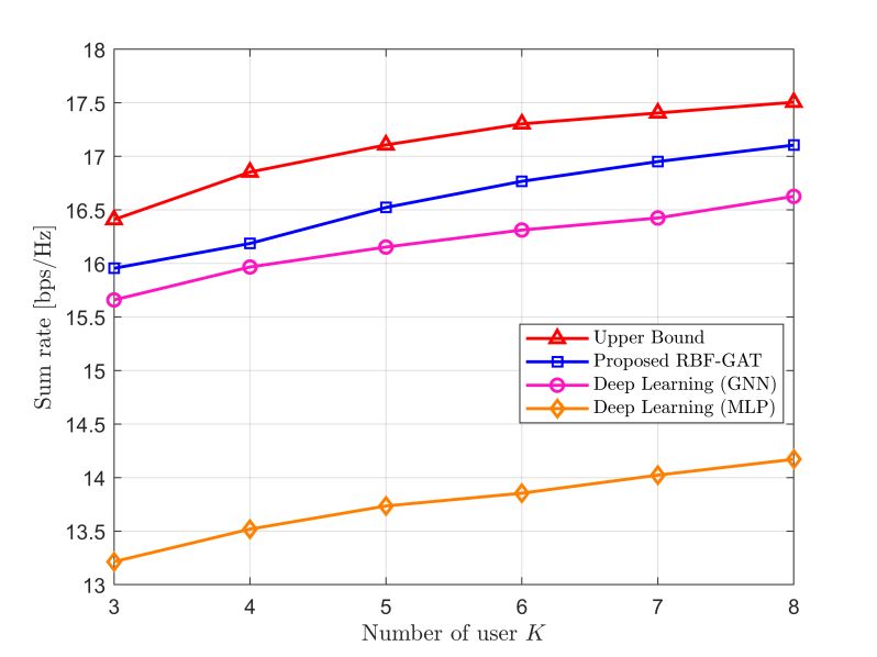
Preprints (www.preprints.org) | NOT PEER-REVIEWED | Posted: 31 January 2022 doi:10.20944/preprints202201.0452.v1
graph attention networks (RBF-GAT) under well pre-trained conditions can achieve an
approximate optimal sum rate with extremely low computational complexity.
The remainder of this paper is organized as follows. Section 2 introduces the IRS-
assisted LEO satellite communication system model. Section 3 describes the detailed ar-
chitecture of RBF-GAT and the training process. Section 4 gives the simulation results and
the complexity analysis. Section 5 presents the concluding remarks of this paper.
Notations: Boldface letters are used to denote vectors or matrices. mn , mn , and
m
represent the m n complex, real matrices and m-dimensional real vector, respec-
tively. The distribution of complex Gaussian random variables with mean μ and variance
σ 2 are denoted by (μ ,σ 2 ) . The term diag() denotes the diagonalization of the vector, and
() denotes the transpose of the matrices. The symbol denotes the Hadamard product.
2. System Model
2.1. Signal Model
As illustrated in Figure. 1, this paper considers an IRS-assisted downlink LEO satel-
lite communication system in IoRT networks. The LEO satellite is equipped with an array-
fed reflector antenna, which comprises M feeds and can mostly provide M beams. Within
the coverage area of a satellite beam, there are K randomly distributed single-antenna mo-
bile users. The direct link between the satellite and users suffers severe attenuation due to
heavy shadowing, thus, an IRS is implemented to assist the communications. The IRS is
composed of N = Nt Nt reflecting elements and is attached to a smart controller for tun-
ing phase shifts at each reflecting element. Nt represents the number of array elements
uniformly placed along the axis. The channels from the LEO satellite to IRS and user k,
N M
k = 1, ,K are denoted by G and hkd 1M
, respectively, while that from the
1N
IRS to user k is denoted by . As such, we let Θ = diag[e jθ1 , , e jθN ] be
hkr
the phase shift matrix of IRS, where θn [0,2π] is the phase shift of the n-th reflection
element.
This paper considers that the LEO satellite carries out superposition coding before
broadcasting signals to the users. Thus, the transmitted signal for all users at the satellite
M1
K
at time t is written as x (t ) = wk xk (t ) , where wk and xk (t ) represent the pre-
k=1
coding vector and transmitted symbol for the k-th user, respectively. Hence, the signal
received by the k-th user is:
( ) w x (t) + n (t)
K
yk (t ) = hkd + hkr ΘG i i k (1)
i=1
where nk (t) is additive white Gaussian noise (AWGN) at the k-th user with a zero mean
and unit variance. Accordingly, the signal-to-interference plus noise ratio (SINR) of user k
can be expressed as:
( h + h ΘG) w
2
d r
k k k
SNIRk =
( h + h ΘG) w
2 (2)
d
k
r
k i + k2
ik
In addition, we assume that the Doppler shift caused by the LEO satellite and users’
mobility can be perfectly compensated at the received end. Therefore, we ignore its influ-
ence in the following.
Preprints (www.preprints.org) | NOT PEER-REVIEWED | Posted: 31 January 2022 doi:10.20944/preprints202201.0452.v1
LEO
IRS
controller
Uplink
Downlink
Control link
hkd 1 M
N M
IRS G
hkr 1 N
user 2
User
user 1 user k
Figure 1. IRS-assisted downlink LEO satellite communication system.
2.2. Channel Model
To realistically model the propagation characteristics of the satellite channel, the im-
pact of path loss, atmospheric attenuation, and satellite beam gain should be accounted
for. The downlink channel between the satellite and the ground device k can be expressed
as [26]:
1 1
hk = C k bk2 rk2 hk , k = 0,1, ,K (3)
where C k is the large-scale fading efficient, which can be calculated by:
2
λ Gk
Ck = (4)
4πdk TB
where dk , λ and Gk represent the propagation distance, carrier wavelength and receive
antenna gain, respectively. =1.38 10-23 J / m is Boltzman’s constant, B is the carrier
bandwidth, and T represents the receive noise temperature. bk =[bk,1 , ,bk,M ] in Eq. (3) is
an M-dimensional beam radiation pattern vector, where the m-th element bk can be
approximated by [26,27]:
J1 ( uk,m ) J3 ( uk,m )
2
bk,m = bmax + 36 (5)
2uk,m 2u 2
k,m
where uk,m =2.07123sin(φk,m ) / sin(φk,3dB ) , φk,m is the angle between the m-th satellite
beam centre and user k, k ,3dB is the 3-dB angle for the k-th user. bmax is the maximal
satellite antenna gain. J1 () and J3 () are the first and third orders of the first-kind Bessel
function, respectively. Moreover, rk in Eq. (3) is also an M-dimensional vector in which
represents the rain attenuation coefficient and its form of dB follows lognormal random
distribution ln ( 20lg( rk,m ) ) ~ (μm ,σm
2
) . Moreover, we adopt shadowed Rician fading as
the satellite channel fading model, which is proposed in [28] and has been widely usedPreprints (www.preprints.org) | NOT PEER-REVIEWED | Posted: 31 January 2022 doi:10.20944/preprints202201.0452.v1
in prior studies. In this model, the probability density function of |hk |2 can be expressed
as:
mk
2λk mk 1 x Ωk x
f|h |2 ( x) = exp(− ) 1 F1 mk , 1, ,x 0 (6)
k
2λk mk + Ωk 2λ k 2λk 2λk (2λk mk +Ωk )
where 1 F1 (a; b; c) is the confluent hypergeometric function and 2λk and Ωk are the
average power of the scatter component and LoS component, respectively. mk 0
denotes the Nakagami-m parameter. Therefore, the channel fading coefficient hk can be
represented as hk = (λk ,mk ,Ωk ) . When k = 0, we denote h0 represents the channel between
the satellite and IRS. In this paper, we assume that the channels of satellite-IRS links un-
dergo infrequent light shadowing (ILS), while satellite-user links experience frequent
heavy shadowing (FHS) [29]., i.e., h0 hk , k {1, 2, , K} .
For the channel model between IRS and user k, both LoS and no line-of-sight (NLoS)
components are considered, so we model channel hkr as Rician fading channels:
ξ los 1 nlos
hkr = βk h + hk (7)
1+ ξ k 1+ ξ
where βk is the path loss from the IRS to user k and can be modelled as 30 + 22log(dk ) ,
dk is the distance between the RIS and the k-th user. ξ is the Rician factor, and hknlos is the
NLoS component vector, which is a complex Gaussian distributed with zero mean and
unit variance. Moreover, hklos = [a(k , k )1 , , a(k , k )N ] represents the LoS component
vector, and the n-th element a(k , k )n can be given by:
2 πd
j snsin(k )cos( k )+ insin( k ) (8)
a(k , k )n =e λ
where sn = mod(n - 1,Nt ) and in = (n - 1) / Nt . k and k are the azimuth and elevation
angles of arrival (AoA) from the IRS to user k. d is the interelement spacing of IRS, and
we assume d / λ = 2 .
2.3. Problem Formulation
This paper aims to enable LEO satellites to transmit as much data as possible within
a limited time window. Thus, we investigate a sum-rate maximization problem by jointly
optimizing the precoding matrix at the LEO satellite and reflect beamforming at the IRS,
which can be given as
K
P1: max
w,Θ
R
k =1
k (9a)
s.t. θn [0,2π], n {1, 2, ,N}, (9b)
K
w PL .
2
k (9c)
k =1
where (9b) and (9c) are the constraints of the phase shift of IRS and the maximum
transmit power of the LEO satellite, respectively. Due to the objective function (9a) is
nonconvex [14], and the traditional optimization algorithms usually require many
iterations and are not suitable for high-speed scenarios. To solve the problem with low
complexity, we propose an RBF-GAT to establish a direct mapping from the received
pilots and network topology to the satellite and IRS beamforming.Preprints (www.preprints.org) | NOT PEER-REVIEWED | Posted: 31 January 2022 doi:10.20944/preprints202201.0452.v1
3. Proposed RBF-GAT Framework
To acquire the downlink instantaneous CSI of the LEO satellite, we follow the litera-
ture [19] and propose a pilot transmission strategy to design the uplink pilots and the IRS
phase shifts in the pilot phase. Specifically, all users send their pilot sequences with length
L to the satellite simultaneously. Each pilot can be decorrelated at the LEO satellite because
all users’ pilot sequences are designed to be orthogonal. We denote the received pilots of
user k at the satellite as pk , which contains rich CSI between satellite and user k. The con-
ventional approach of acquiring CSI uses minimum mean-squared error (MMSE), and its
calculation is very complicated, especially for the IRS cascade channel.
Notably, GAT is an effective way to process structured data that are represented as
a graph. In this work, the distribution of users can be regarded as a graph. K users consti-
tute nodes of the graph, and each node is encoded as a feature vector denoted as ak , which
is transmitted to the satellite via uplink and contains the common features (e.g., the loca-
tions of IRS and satellite) and the private features (e.g., user locations, category and prior-
ity). GAT can track the spatial fluctuations of the network in real-time by processing this
feature.
In this section, we commit to training an RBF-GAT network to directly establish the
mapping from pk and ak to the precoding matrix and reflect beamforming to maximize
the system sum rate. We first introduce the RBF-GAT architecture in detail and then dis-
cuss the unsupervised training approach.
3.1. RBF-GAT Architecture
Our network consists of multiple GATs layers and multiple FC layers, as illustrated
in Figure. 2. First, for the raw feature ak obtained from the scenario, we need to map such
vectors into a higher-dimensional space by a GAT layer, since the raw low-dimension fea-
ture contains less network topological information. The input to the GAT layer is a set of
node features, a = {a1 ,a2 , ,aK }, ak F , where F is the dimension of raw features in
each user. To transform ak into a higher-level feature space of F' dimension, a shared
weight matrix, W F F , is applied to perform a linear transformation. We implement a
'
shared self-attention mechanism Atten(,) to calculate the attention coefficients of the
user and its adjacent users:
F'
eij = Atten(Wai , Wa j ) , Atten : F
→ (10)
Note that to indicate the topological information of the network, we computed the
attention coefficients only when the distance between user i and user j was within certainPreprints (www.preprints.org) | NOT PEER-REVIEWED | Posted: 31 January 2022 doi:10.20944/preprints202201.0452.v1
D FC Layers Normalization
GAT-1 Layer GAT-2 Layer and Liner Layers
c1 0
c 1
a1 pilots fw
p1
aj k
ak cj k ck Avg
Avg a1'
W W W1 W1 w
W Atten() Atten()
c2 W1
c20
a2 pilots
softmax p2 softmax
Avg
Avg a2'
fΘ
() ()
cK
c K0
pilots pK
Θ
aK
Avg
head-1 Avg aK' head-1
H-head H-head mean mean
Figure 2. The architecture of the proposed RBF-GAT.
threshold. For easy comparison, a softmax function is applied to normalize the
coefficients across different adjacent users, and the final normalized coefficients αij are
obtained as
exp(eij )
αij = softmax(eij ) =
jli
exp(eij )
(11)
where li is the set of adjacent users including itself in the current neighbourhood scope
of the i-th user. Then, these coefficients are used to calculate a linear combination of the
features to produce the output features for the current network user:
a'k =
jl
αkj Wa j
(12)
k
'
where () represents a nonlinear activation function and a'k F is the output vector
of the single-head attention mechanism. To make the self-attention learning process
more stable, a multi-head attention mechanism is used in this paper, which can be
regarded as multiple single-head attentions executed independently in parallel, and
taking the average as the output, can be represented by:
1 H
a'k =
H αhkj W h a j
(13)
h=1 jlk
where H is the number of attention heads, Wh represents the shared weight matrix of
the h-th attention head.
Then, we concatenate the received pilot pk and the output features a'k as the com-
posite features of user k and denote them as c k , which is a (2ML + F' ) dimensional vector
because all received pilots are decomposed into real and imaginary parts.
ck =[(pk ) , (a'k ) ] (14)Preprints (www.preprints.org) | NOT PEER-REVIEWED | Posted: 31 January 2022 doi:10.20944/preprints202201.0452.v1
Significantly, c k contains rich information about both the instantaneous CSI and
network topology structure, so we use it as the input to the composite neural network.
After c k pass through the GAT-2 layer, D FC layers and a normalization layer, the final
output can be mapped directly to the precoding matrix of the satellite and the phase shift
of the IRS.
We denote c 0k as the output of the second GAT layer, which is also the input of the
first FC layer. According to Eq. (13), c 0k can be expressed as
1 H
c0k =
H α 'h h
kj W1 ck
(15)
h=1 jlk
F''( 2 ML+F')
where α'h
kj and W1
h
are the normalized attention coefficients and the
shared weight matrix of the h-th multihead attentions, respectively. In addition, we chose
the node-wise mean function as an aggregation function to aggregate the output
characteristics of the GAT layer and concatenate it into each FC layer by using skip
connect.
After D FC layers, the final output vectors, denoted as ckD , are passed to the normal-
ization layer to produce the precoding matrix w and phase shift matrix Θ while ensur-
ing the constraint of phase shift and transmit power. As with [20], we input c kD to the
linear layer fw () with 2MK FC units and the linear layer fΘ () with 2N FC units. Then,
the normalization layer outputs the real and imaginary components of the optimization
variables. Finally, the complex solution can be obtained by combining the real and imagi-
nary components.
3.2. Unsupervised training
Since it is difficult for the IRS-assisted LEO satellite system to obtain data labels, we
cannot train it by a classic deep learning algorithm with supervised learning techniques.
Thus, unsupervised training is adopted for training the network. We define the loss func-
tion as
T K
ω R
1
Loss = - k k (16)
T i=1 k=1
where T represents the total number of training samples in a batch. To generate a training
dataset, first, we generate the channel data according to the channel model discussed in
Section 2. Then, all users transmit orthogonal pilot signals and additional information (i.e.,
location, priority, etc.) to the satellite. The LEO satellite can recover the pilots of all users
from the received pilots and use it as part of the input of the neural network. The details
of the training procedure are summarized in Algorithm 1.
Note that our model is trained offline, thus, the training process does not increase
its computational complexity. During training, we use the stochastic gradient descent
method to update the neural network parameters to minimize the loss function, which is
equivalent to maximizing the objective function P1.Preprints (www.preprints.org) | NOT PEER-REVIEWED | Posted: 31 January 2022 doi:10.20944/preprints202201.0452.v1
Algorithm 1 Training procedure for RBF-GAT.
Input: learning rate α , maximal epoch Ep , batch size N b , training samples T , I ite .
Output: optimal network weights parameter Φ
1: Randomly initialize network parameter Φ .
2: Calculate loss L0 according to E.q (16) and initialize s = 0 .
3: for i = 1, ,Ep do
4: for jite = 1, ,Iite do
5: Initialize the phase shift matrix Θ and generate received pilot according to [19].
6: Randomly select T samples to compose a batch task.
7: Update the network weights parameter as Φ' by Adam optimizer.
8: end for
9: Calculate loss Li according to E.q (16).
10: if Li > Li-1 do
11: Set s = 0 , Φ Φ' and save network weights.
12: else
13: Update s s + 1 and judge whether the learning rate α needs to be updated.
14: end if
15: end for
4. Simulation and Numerical Results
This section uses numerical simulations to evaluate the performance achieved by the
proposed RBF-GAT for the sum-rate maximization problem. We first set the simulation
parameters of the training neural network and IRS-assisted LEO satellite communication
system. Then, we compare the RBF-GAT with several benchmarks proposed in prior
works. Finally, we show the simulation results and analyze the computational complexi-
ties of the proposed RBF-GAT method.
4.1. Simulation Parameter Setting
We use four attention heads (H=4) and adopt three FCs (D=3) in the proposed net-
work. The names of the FC layers are denoted as f1 , f2 and f3 , respectively. In addition,
we set ak as a 10-dimensional vector (F=10) that contains the priority information and the
location information of user k, IRS and LEO satellites. The parameters of all layers are
summarized in Table 1.
Table 1. The parameters of RBF-GAT.
Layer name Input dimension Output dimension Activation function
GAT1 K 10 K 512 LeakyReLU
GAT2 K (512 + 2ML) K ×1024 LeakyReLU
f1 K 1024 2048 ReLU
f2 2048 1024 ReLU
f3 1024 512 ReLU
fw 512 2MK ReLU
fΘ 512 2N ReLUPreprints (www.preprints.org) | NOT PEER-REVIEWED | Posted: 31 January 2022 doi:10.20944/preprints202201.0452.v1
For network training, we use the Adam optimizer with an initial learning rate
α=0.001 , the number of maximal epochs Ep is set to 350, and for each epoch, we generate
Iite = 100 iterations to update the weights of the network. The batch size N b is set to 1000.
To accelerate the convergence, the learning rate decays by a factor of 0.3 when the valida-
tion loss does not decrease for 5 consecutive epochs. Due to the statistical properties of the
channel and the noise in the uplink pilot transmission, all the calculation results are gen-
erated based on averaging over 1000 instances.
For the considered IRS-assisted LEO satellite system, we assume that the LEO satel-
lite altitude is 1000 km and that the satellite is equipped with M=8 antennas. An IRS with
64 passive element locations at (0,0) and height 20 m. IRS is configured as an 8x8 uniform
rectangular array. There are 6 terrestrial users uniformly distributed in a square area of [0,
200] m x [0, 200] m. We set the length of the uplink pilots to L=20 for each user, and the
user’s transmission power to 15 dBm. The uplink channels from users to IRS, from IRS to
the LEO satellite, and from users to the LEO satellite are generated according to the chan-
nel model discussed in Section 2. The details of the coefficients are given in Table 2.
Table 2. Simulation parameters in the IRS-assisted LEO satellite communication network.
Parameter Definition Value
PL Satellite maximum transmit power 30 dBW
ν/λ Carrier frequency 20 GHz
Gk / T User received gain per to noise temperature 15 dB/K
B Bandwidth 25 MHz
φk,m Beam angles between IRS/user and satellite 0.01o~0.5o
φk,3dB 3-dB angle 0.4o
bmax Maximal satellite antenna gain. 52 dBi
μm Rain fading mean -2.6 dB
2
σm Rain fading variance 1.63 dB
ξ Rician factor 10
ILS fading parameters between satellite to
h0 (19.4, 0.158, 1.29)
IRS channel
HFS fading parameters between satellite to
hk (0.739, 0.063, 8.97 10-4 )
user channel
4.2. Benchmark Schemes for Comparison
After the RBF-GAT was trained offline, we compared its performance with the fol-
lowing benchmarks:
Upper Bound: Let the CSI of all channels is perfectly known at the IRS and the LEO
satellite, and we optimize the sum-rate maximization problem by the block coordinate
descent (BCD) algorithm proposed in [14], which can be treated as the system perfor-
mance upper bound but, in reality, it is difficult to realize. We stop the BCD algorithm
after 2000 iterations.
Deep Learning(GNN): Adopt a GNN architecture proposed in [24] to capture the
interactions among all users and the LEO satellite. The user locations and received pilots
are directly concatenated as the input feature, and then train the model offline in an un-
supervised manner.
Deep Learning(MLP): Design a multi-layer perceptron (MLP), which is composed
of a simple network including multiple layers with several neurons, to establish the map-
ping from pilots and location to beamforming. This method has been studied in [30].Preprints (www.preprints.org) | NOT PEER-REVIEWED | Posted: 31 January 2022 doi:10.20944/preprints202201.0452.v1
4.3. Numerical Results
In this subsection, we present the numerical results of the proposed approach. We
assume that the users’ locations are fixed within a time slot, the time slot is small enough
and the low-complexity RBF-GAT can implement active and passive beamforming within
the time slot.
Figure 3. The convergence rate with different training parameters.
To verify the convergence rate of the proposed RBF-GAT scheme, we plot the loss
value during training versus the number of epochs with three different training parame-
ters. Figure 3 shows that the proposed scheme converges to a locally optimal solution in
less than 200 training epochs. In addition, the smaller the number of IRS reflection ele-
ments or users, the faster the convergence speed of the algorithm. This is because the
number of users or IRS elements is positively correlated with the number of weight pa-
rameters to be trained.
Figure 4. The sum rate versus the number of users K with M=8, N=64, L=20 and PL =30dBW .
Figure 4 shows the sum-rate versus the number of users under different schemes.
The sum-rates under all considered schemes increase with an increasing number of users
K, and the larger the value of K is, the slower the growth trend. This phenomenon can be
explained by the concavity of the log function from the sum rate. Moreover, both RBF-Preprints (www.preprints.org) | NOT PEER-REVIEWED | Posted: 31 January 2022 doi:10.20944/preprints202201.0452.v1
GAT and GNN can achieve performance close to the upper boundary, but the proposed
RBF-GAT consistently outperforms GNN, and the gap increases with K. The reason for
the increase is that the LEO satellite is insensitive to user’s location information, in contrast
to GNN directly merging the position coordinates of the user, RBF-GAT can effectively
capture the dynamic network topology by GAT layers. Thus, the proposed RBF-GAT is
more suitable for IRS-aided LEO satellite dynamic scenario communication.
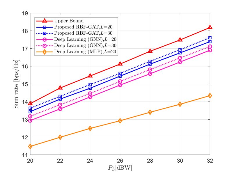
Figure 5. The sum-rate versus the LEO satellite transmit power PL .
Figure 6. The sum-rate versus the number of IRS elements N = Nt Nt .
Figure 5 illustrates the sum-rate of different schemes with respect to the transmit
power PL when N = 64. The sum rate increases for all considered schemes as the trans-
mission power increases. As we expected, the performance of RBF-GAT is always closest
to the upper boundary under the condition of equal pilot length. In addition, as the pilot
length increases, the rate sum also increases but never exceeds the upper boundary. This
is because the longer the pilot signal received is, the richer the CSI contained. Thus, more
features can be learned by the neural network. On the other hand, increasing the pilot
length will also lead to a larger delay in data transmission. In practical applications, we
should make trade-offs according to different requirements.Preprints (www.preprints.org) | NOT PEER-REVIEWED | Posted: 31 January 2022 doi:10.20944/preprints202201.0452.v1
Figure 6 shows the sum-rate versus the number of elements of the IRS in four dif-
ferent schemes. In Figure 5, we set the number of feeds at LEO satellite as M = 8, pilot
length as L=20, and the transmit power of LEO satellite as PL =30dBW. From Figures 4
and 5, we can observe that both the number of IRS elements and the increase in transmit
power can improve the sum-rate. However, compared to increasing the transmit power,
increasing the IRS elements to improve the rate performance is a more energy-efficient
scheme due to the IRS elements being passive. The above numerical simulations further
validate the robustness and effectiveness of our proposed RBF-GAT schemes.
4.4. Computational Complexity Analysis
The complexity of the BCD is Ο( I o (2NMK + KM2 + K 2 M 2 )) [14], where I o is the
number of iterations and does not include the complexity of the channel estimation. For
IRSs with passive elements, the conventional least square channel estimation methods
have a computational complexity of Ο( LKMN) with L < NM. In our proposed RBF-GAT
method, the channel estimation is omitted. For the training stage, let Z1, Z2, and Z3 denote
the number of neurons in the three FC layers in turn. The computational complexity of
the proposed RBF-GAT scheme in each iteration is
' '' ' ''
Ο(KFF + KF (2 ML + F ) + F Z1 + Z1Z2 + Z2 Z3 + 2Z3 MK + 2Z3 N ) . In the training phase, the
model is trained for Ep epochs, with each epoch being I ite iterations. Hence, the total com-
putational complexity of the proposed method is Ο( Ep Iite (KFF ' + KF '' (2ML + F ' ) + F'' Z1 +
Z1Z2 + Z2 Z3 + 2Z3 MK + 2Z3 N )). The high computational complexity training
process is performed offline. Therefore, theactual computational complexity of our
proposed method is only linear in M, N and K.
Due to the GNN and MLP methods are also established by neural networks, and
they have approximate computational complexity as the proposed RBF-GAT. However,
the proposed method achieves better performance, which is shown in the previous sub-
section. It is easy to see that the proposed RBF-GAT method has lower computational
complexity and has significant advantages in the dynamic scenarios of satellite commu-
nication.
5. Conclusions
In this paper, we investigated the IRS-aided LEO satellite communication system.
Specifically, we formulated a sum-rate maximization problem by optimizing the satellite
precoding and IRS beamforming jointly. To tackle the time-varying network topology and
high transmission delay of satellite communication, an RBF-GAT was presented to estab-
lish a direct mapping from the received pilots and network topology to the satellite and
IRS beamforming, and the unsupervised learning mechanism was used to train this net-
work offline. Compared with traditional beamforming methods, the proposed approach
has the ability to capture the dynamic network topology and lower computational com-
plexity. Therefore, it is more suitable for dynamic LEO satellite communication scenarios.
The simulation results corroborated that the proposed scheme can achieve approxi-
mate performance compared with an optimal solution.
Author Contributions: Conceptualization, H.C.; formal analysis, W.Z and W.F.; Investigation,
W.Z.; Writing—original draft, W.Z and J.F.; Writing—review & editing, H.C. J.F. and W.Z. All
authors have read and agreed to the published version of the manuscript.
Funding: This work was supported by the National Natural Science Foundation of China under
Grant Nos. 51877015, U1831117, U20A20157, and U1931129.
Data Availability Statement: Not applicable.Preprints (www.preprints.org) | NOT PEER-REVIEWED | Posted: 31 January 2022 doi:10.20944/preprints202201.0452.v1
Conflicts of Interest: The authors declare no conflict of interest.
References
1. Araniti. G.; Bisio, I.; De Sanctis. M.; Cosmas, J. Multimedia content delivery for emerging 5G-satellite networks. IEEE
Trans. Broadcast. 2016, 62, 10-23.
2. Zhang, Z.; Xiao, Y.; Ma, Z.; Xiao, M.; Ding, Z.; Lei, X.; Karagiannidis, G.K.; Fan, P. 6G wireless networks: Vision, requirements,
architecture, and key technologies. IEEE Veh. Technol. Mag. 2019, 14, 28-41.
3. Sheng, M.; Zhou, D.; Liu, R.; Wang, Y.; Li, J. Resource mobility in space information networks: Opportunities, challenges, and
approaches. IEEE Netw. 2019, 33, 128-135.
4. Jia, Z.; Sheng, M.; Li, J.; Niyato, D.; Han, Z. LEO-Satellite-Assisted UAV: Joint Trajectory and Data Collection for Internet of
Remote Things in 6G Aerial Access Networks. IEEE Internet Things J. 2021, 8, 9814-9826.
5. Zhen, L.; Bashir, A.K.; Yu, k.; Ai-Otaibi, Y.D.; Foh, C.H.; Xiao, P. Energy-Efficient Random Access for LEO Satellite-Assisted 6G
Internet of Remote Things. IEEE Internet Things J. 2021, 8, 5114-5128.
6. Zhang, Y.; Wang, Z.; Huang, Y.; Wei, W.; Pedersen, G.F.; Shen, M. A Digital Signal Recovery Technique Using DNNs for LEO
Satellite Communication Systems. IEEE Trans. Ind. Electron. 2021, 68, 6141-6151.
7. Gao, Z,; Liu, A.; Han, C.; Liang, X. Max Completion Time Optimization for Internet of Things in LEO Satellite-Terrestrial Inte-
grated Networks. IEEE Internet Things J. 2021, 8, 9981-9994.
8. Huang, Q.; Lin, M.; Wang, J.B.; Tsiftsis, T.A.; Wang, J. Energy Efficient Beamforming Schemes for Satellite-Aerial-Terrestrial
Networks. IEEE Trans. Comm. 2020, 68, 3863-3875.
9. Ma, T.; Zhou, H.; Qian, B.; Cheng, N.; Shen, X.; Chen, X.; Bai, B. UAV-LEO Integrated Backbone: A Ubiquitous Data Collection
Approach for B5G Internet of Remote Things Networks. IEEE J. Sel. Areas Commun. 2021, 39, 3491-3505.
10. Luan, Z.; Jia, H.; Wang, P.; Jia, R.; Chen, B. Joint UAVs Load Balancing and UEs Data Rate Fairness Optimization by Diffusion
UAV Deployment Algorithm in Multi-UAV Networks. Entropy 2021, 23, 1470.
11. Wu, H.; Lyu, F.; Zhou, C; Chen, J.; Wang, L.; Shen, X. Optimal UAV caching and trajectory in aerial-assisted vehicular networks:
A learning-based approach. IEEE J. Sel. Areas Commun. 2020, 38, 2783–2797.
12. Wu, Q.; Zhang, R. Towards smart and reconfigurable environment: Intelligent reflecting surface aided wireless networks. IEEE
Commun. Mag. 2020, 58, 106-112.
13. Gao, Y.; Guo, D.; Xiong, J.; Ma, D. Intelligent Reflecting Surface Assisted Multi-User Robust Secret Key Generation for Low-
Entropy Environments. Entropy 2021, 23, 1342.
14. Guo, H.; Liang, Y.C.; Chen, J.; Larsson, E.G. Weighted Sum-Rate Maximization for Reconfigurable Intelligent Surface Aided
Wireless Networks. IEEE Trans. Wirel. Commun. 2020, 19, 3064-3076.
15. Wu, Q.; Zhang, R. Intelligent Reflecting Surface Enhanced Wireless Network via Joint Active and Passive Beamforming. IEEE
Trans. Wirel. Commun. 2019, 18, 5392-5409.
16. Xu, S.; Liu, J.; Cao, Y.; Li, J.; Zhang, Y.; Intelligent Reflecting Surface Enabled Secure Cooperative Transmission for Satellite-
Terrestrial Integrated Networks. IEEE Trans. Veh. Technol. 2021, 70, 2007-2011.
17. Zheng, B.; Zhang, R. Intelligent Reflecting Surface-Enhanced OFDM: Channel Estimation and Reflection Optimization. IEEE
Wirel. Commun. Lett. 2020, 9, 518-522.
18. Wang, Z.; Liu, L.; Cui, S. Channel Estimation for Intelligent Reflecting Surface Assisted Multiuser Communications: Framework,
Algorithms, and Analysis, IEEE Trans. Wirel. Commun. 2020, 19, 6607-6620.
19. Chen, J.; Liang, Y.C.; Cheng, H.V.; Yu, W. Channel estimation for reconfigurable intelligent surface aided multi-user mmWave
MIMO systems. To appear in IEEE Trans. Wirel. Commun. 2021. [Online]. Available: https://arxiv.org/abs/1912.03619.
20. Guan, X.; Wu, Q.; Zhang, R. Anchor-Assisted Channel Estimation for Intelligent Reflecting Surface Aided Multiuser Commu-
nication. IEEE Trans. Wirel. Commun. 2021. [Online]. Available: http://arxiv.org/abs/2008.00622.
21. Zhang, Y.; Wu, Y.; Liu, A.; Xia, X.; Pan. T.; Liu, X. Deep Learning-Based Channel Prediction for LEO Satellite Massive MIMO
Communication System. IEEE Wirel. Commun. Lett. 2021, 10, 1835-1839.
22. Yang, H.; Xiong, Z.; Zhao, J.; Niyato, D.; Xiao, L.; Wu, Q. Deep Reinforcement Learning-Based Intelligent Reflecting Surface for
Secure Wireless Communications. IEEE Trans. Wirel. Commun. 2021, 20, 375-388.
23. Ge, Y.; Fan, J. Beamforming Optimization for Intelligent Reflecting Surface Assisted MISO: A Deep Transfer Learning Approach.
IEEE Trans. Veh. Technol. 2021, 70, 3902-3907.
24. Jiang, T.; Cheng, H.V.; Yu, W. Learning to Reflect and to Beamform for Intelligent Reflecting Surface With Implicit Channel
Estimation. IEEE J. Sel. Areas Commun. 2021, 39, 1931-1945.
25. Velikovic, P.; Cucurull, G.; Casanova, A.; Romero, A.; Liò, P.; Bengio, Y. Graph attention networks. In Proceedings of the 6th
International Conference on Learning Representations, ICLR 2018, Vancouver, BC, Canada, 30 April–3, 1–12, May 2018.
26. Zheng, G.; Chatzinotas, S.; Ottersten, B. Generic optimization of linear precoding in multibeam satellite systems. IEEE Trans.
Wirel. Commun. 2012, 11, 2308–2320.
27. Arnau, J.; Christopoulos, D.; Chatzinotas, S.; Mosquera, C.; Ottersten, B. Performance of the multibeam satellite return link with
correlated rain attenuation. IEEE Trans. Wirel. Commun. 2014, 13, 6286-6299.
28. Abdi, A.; Lau, W.C.; Alouini, M,S.; Kaveh, M. A new simple model for land mobile satellite channels: first- and second-order
statistics. IEEE Trans. Wirel. Commun. 2003, 2, 519-528.Preprints (www.preprints.org) | NOT PEER-REVIEWED | Posted: 31 January 2022 doi:10.20944/preprints202201.0452.v1
29. An, K,; Lin, M.; Liang, T.; Wang, J.B.; Wang, J.; Huang, Y.; Lee Swindlehurst, A. Performance Analysis of Multi-Antenna Hybrid
Satellite-Terrestrial Relay Networks in the Presence of Interference. IEEE Trans. Comm. 2015, 63, 4390-4404.
30. Jiang, T.; Cheng, H.V.; Yu, W. Learning to Beamform for Intelligent Reflecting Surface with Implicit Channel Estimate. In Pro-
ceedings of the IEEE Global Communications Conference, Taipei, Taiwan, 7-11 December 2020.You can also read