SANS Institute Information Security Reading Room - SANS.org
←
→
Page content transcription
If your browser does not render page correctly, please read the page content below
SANS Institute
Information Security Reading Room

Looking Under the Rock:
Deployment Strategies for TLS
Decryption
______________________________
Chris Farrell

Copyright SANS Institute 2020. Author Retains Full Rights.

This paper is from the SANS Institute Reading Room site. Reposting is not permitted without express
written permission.
ts
                                                                                                 gh
                              Looking Under the Rock:

                                                                                             Ri
                       Deployment Strategies for TLS Decryption

                                                                                         ll
                                                                                     Fu
                                        GIAC (GCIA) Gold Certification

                                                                               ns
                                                                           ai
                                        Author: Chris Farrell, chrisf@iquest.net

                                                                        et
                                             Advisor: Stephen Northcutt
                                            Accepted: December 29, 2017

                                                                  rR
                                                             ho
                                                         ut
                                                    ,A Abstract
                                                te
                                            itu
                                        st

               Attackers can freely exfiltrate confidential information all while under the guise of
               ordinary web traffic. A remedy for businesses concerned about these risks is to decrypt
                                    In

               the communication to inspect the traffic, then block it if it presents a risk to the
                              NS

               organization. However, these solutions can be challenging to implement. Existing
               infrastructure, privacy and legal concerns, latency, and differing monitoring tool
                        SA

               requirements are a few of the obstacles facing organizations wishing to monitor
               encrypted traffic. TLS decryption projects can be successful with proper scope definition,
                     e

               an understanding of the architectural challenges presented by decryption, and the options
                Th

               available for overcoming those obstacles.
          18
     20
 ©

© 2018 The SANS Institute                                                                        Author retains full rights.
ts
Looking under the Rock 2
gh
1. Introduction and TLS Use Cases
Ri
ll
Fu
The internet has evolved from its beginnings as a simple connection between
universities to the vast global network we know today. It acts as the information
ns
infrastructure which supports many aspects of our lives. Critical confidential information
ai
travels across the internet continually. The original developers of the internet focused on
et
rR
transferring information that recipients would understand upon arrival (Gromov, 1995).
Protecting confidential data in transit would later be addressed using encryption which
ho
utilizes Transport Layer Security (TLS).
ut
,A
Web communications te
Web browsing is the most prevalently used internet application. An estimated 4.6
itu
billion web pages exist on the internet; that number continues to grow steadily (Kunder,
st
2017) The servers of the original World Wide Web were designed to produce static web
In
pages quickly. The information created was considered public information functioning
NS
similarly to a roadside billboard.
SA
Over time, the need to deliver information only to intended recipients evolved. A
method had to be designed to protect the data from being intercepted by unintended
e
Th
audiences. Jinwoo Hwang describes in detail the historical evolution of SSL to TLS v1.3
in his research at the IBM DeveloperWorks library (Hwang, 2012) (Whitteker, 2016)
18
20
TLS-VPNs
©
TLS VPNs are another popular use of TLS technology. Instead of encrypting only
the web traffic to/from a web server, the TLS VPN encapsulates all sensitive traffic. This
encryption protects all applications with TLS encryption. At the destination, the endpoint
server decrypts and delivers the data.
An example is a remote employee who needs to connect to the employer's
network. Other encryption technologies exist which provide this functionality, but their
use typically requires firewall configuration changes at each site the employee may visit.
However, TLS outbound traffic is enabled on most firewalls to allow secure web
browsing. A TLS-VPN connection takes advantage of this already-open pinhole through
Chris Farrell, chrisf@iquest.net
© 2018 The SANS Institute Author retains full rights.ts
Looking under the Rock 3
gh
the outbound firewall to create the encrypted connection (Ferrigni, 2003). The ability to
Ri
encrypt almost any communication within a TLS-VPN tunnel is powerful. It protects the
ll
Fu
encrypted traffic from any prying eyes on the networks which the traffic traverses. This
capability is also useful to those who wish to move malicious traffic across networks. The
ns
encryption protects the attacker’s traffic from being monitored and detected by the
ai
network’s defenders.
et
rR
ho
2. Malicious Use Cases
ut
The obstruction created between those who can decrypt the communication and
,A
those who cannot decrypt allows commercial transactions and private information to be
te
shared securely. However, the obstacle which protects sensitive, legitimate traffic from
itu
unauthorized access also can be used by those with nefarious intentions to hide their
st
activities from security monitoring systems. Any attacker with the goal of communicating
In
from within a company to any external server now has a very convenient way to make the
NS
connection and hide the details of the communication within the encrypted connection.
SA
Command and Control
e
Th
Malware developers create software for delivery to computers within secured
network perimeters. Once the malware has been successfully delivered and executes on
18
an internal resource, the next step is to make an outbound connection across the secured
20
perimeter to a Command and Control (C&C) server to receive further instructions.
©
Security teams monitor for these types of outbound communications and attempt to detect
and block unauthorized traffic (Butler, 2013). Through the use of TLS, attackers can send
these outbound communications undetected to servers on the internet leveraging the
openings that have been created to allow legitimate web communications. (Liburdi, 2017)
Chris Farrell, chrisf@iquest.net
© 2018 The SANS Institute Author retains full rights.ts
Looking under the Rock 4
gh
Ri
ll
Exfiltration
Fu
Once the malware has been established on an internal device, the next steps are
ns
privilege escalation, lateral movement, and persistence. This process almost always is
ai
done to access the sensitive internal information that the network perimeter was intended
et
to protect.
rR
In most cases, the adversary’s goal is to exfiltrate the data outside the secured
ho
network perimeter. If the attacker utilizes a TLS tunnel similar to a TLS-VPN, the
ut
monitoring systems will be unable to detect the data hidden within the encrypted session.
,A
(Antwerp, 2011) What’s needed is a solution which exposes the hidden data to the
te
enterprise while maintaining the TLS connection across the internet.
itu
st
3. Network-Based Decryption
In
NS
TLS encryption introduces a security blind spot because the data cannot be read
SA
and evaluated. The security monitoring systems must be able to assess the data in its
unencrypted state. The security monitoring systems can then send alerts or block it as
e
Th
needed.
18
Network-based TLS decryption involves placing a gateway server between all of
20
the devices within the secured perimeter and the internet. The internal devices are
configured to recognize and accept the gateway as an intermediary for all outbound TLS
©
connections. When an internal device initiates a legitimate TLS connection, that device
attempts to connect to the external destination and the gateway intercepts the connection.
By acting as a man-in-the-middle, the gateway pretends to be the external
destination and creates an encrypted session with the internal device. This connection
allows the gateway server to decrypt the data for inspection. If done correctly, persons
using the web browsers are not aware the traffic is flowing through an interceptor. The
result is that the browser reports a secure connection with the external destination exists.
Chris Farrell, chrisf@iquest.net
© 2018 The SANS Institute Author retains full rights.ts
Looking under the Rock 5
gh
After the interceptor has decrypted the traffic, the clear-text data can be evaluated
Ri
by security monitoring systems for detection of malicious activity. The security
ll
Fu
monitoring systems deliver alerts or terminate the TLS session, based on the
determination. If the data is determined to be legitimate, the gateway server then creates a
ns
separate encrypted session with the external destination. The destination server does not
ai
know it is communicating with a proxy for the device within the secured perimeter.
et
rR
ho
4. Decryption Obstacles and Solutions
ut
Organizations should consider the obstacles presented by legal and privacy
,A
concerns, architectures, modes of operation, certificates, latency, support and high
te
availability when deploying a technology such as TLS interception.
itu
st
Legal Considerations
In
TLS is one of the most trusted encrypted transports for the international
NS
computing community. With so many people using it to protect their communications,
SA
and internet cloud technologies continuing to expand across geographic borders, it is
essential to consider how international data privacy laws apply to these activities.
e
Th
Individual countries enact data privacy laws with differing degrees of maturity
and complexity. In some instances, communities may work in partnership to create
18
legislation. This form of cooperation is most evident in the European Union (EU) where
20
28 countries have adopted uniform, more stringent data privacy laws.
©
The EU implemented Data Protection Directive 95/46/EC in March 2000. EU
countries are scheduled to adopt the General Data Protection Regulation on May 25th of
2018 (Data Protection Laws of the World, 2017). Although this is an EU regulation, it
applies to any organization regardless of their physical location if they are collecting
personal data of EU residents. The law applies to the residence of the data owner, not the
geographic location of the interception. Another important aspect of this law is the
concept of data ownership. The subject of the data owns the personal information. The
subject must be able to withdraw their consent easily. Additionally, owners have the
Chris Farrell, chrisf@iquest.net
© 2018 The SANS Institute Author retains full rights.ts
Looking under the Rock 6
gh
"Right To Be Forgotten" and must be given a process to have any personal data purged
Ri
from any monitoring systems.
ll
Fu
If a company intends to intercept TLS traffic for information security monitoring,
ns
it must address several fundamental tenets of the law. The first is informed consent which
ai
means that before the company can intercept TLS, it must inform everyone whose data it
et
will monitor. The enterprise also must inform the data owners about why it needs the data
rR
and how it will use the data. Data owners must explicitly grant written consent. The
ho
company must establish a process to allow the data owner to withdraw consent at any
time. Companies may make this a requirement of employment, but careful security
ut
,A
architecture must be applied so that it will monitor only those who have given consent to
TLS interception.
te
itu
Another important aspect of the law is that for any data retained about an
st
individual, a process must be established to allow the individual access to the data free of
In
charge and be able to confirm how the enterprise used the data. Because the value of
NS
intercepted traffic for security reasons diminishes quickly over time, a policy of deleting
SA
the data shortly after it is no longer useful reduces the burden of this requirement. This
practice also addresses several other requirements such as the right to correct inaccurate
e
data, the "Right-To-Be-Forgotten" and data portability. Accordingly, the company must
Th
also be able to demonstrate compliance with these requirements through proper
18
documentation, logging, and continuous risk assessments (Preparing for the General Data
20
Protection Regulation, 2017).
©
Privacy Concerns
In countries where the applicable laws are not as well defined, privacy is still a
concern. With the rapid advancement of technology, it has been difficult for the legal
community to craft laws which address the employee’s expectation of privacy (Smith,
2012). Many factors can contribute to a common law claim to a reasonable expectation of
privacy when a company implements TLS interception. An example is when the
company does not own the device being used to encrypt the communication. If an
employee uses a personal device on the company's WiFi hotspot, the employee's
expectation of privacy may be objectively reasonable. This scenario is especially
Chris Farrell, chrisf@iquest.net
© 2018 The SANS Institute Author retains full rights.ts
Looking under the Rock 7
gh
pertinent if the policies do not explicitly address personal device communications on the
Ri
company network. It may be preferable to exclude the WiFi hotspot from TLS
ll
Fu
interception altogether.
ns
It also may be desirable to exclude some communications from TLS interception
ai
based on the data itself. Examples include communications to finance, banking, wellness,
et
and healthcare sites. If an employer intercepts a TLS session between an employee and
rR
his or hers doctor’s website, the employer should be prepared to protect the Private
ho
Health Information (PHI) to the standards established by the Health Insurance Portability
and Accountability Act (HIPAA) (Department of Health and Human Services, 2000).
ut
,A
This example and others related to their respective industries need to be weighed
carefully for the mutual protection of both the employer and the employee.
te
itu
Serial vs. Parallel Deployment
st
When considering TLS interception, most companies wish to apply key
In
information security technologies to the encrypted traffic. There are many of these
NS
technologies, but three common applications are; Web Proxy, IDS/IPS Signature
SA
Inspection, and Data Loss Protection. Web proxies monitor which websites users visit
and what data users send to these websites. IDS/IPS detects malicious traffic based on
e
Th
known traffic signatures. Data Loss Prevention detects the presence of confidential
information leaving the secured company perimeter.
18
20
4.1 Multiple Interception with Serial Distribution
©
There are several approaches to providing a decrypted data stream to these
applications. A straightforward approach would be to align the technologies in series and
allow each device to decrypt the traffic individually as depicted in Figure 1 – Multiple
Interception with Serial Distribution below.
Figure 1 – Multiple Interception with Serial Distribution
Chris Farrell, chrisf@iquest.net
© 2018 The SANS Institute Author retains full rights.ts
Looking under the Rock 8
gh
The primary issues with this approach are the delays introduced as each device
Ri
decrypts/re-encrypts the data and the increased risk of an interruption of service if any of
ll
Fu
these devices encounters an error. Latency grows every time the decryption process
occurs. Intercepting the data once can be noticed by users. If the traffic must be
ns
intercepted three times before it reaches its destination, the user may have a negative
ai
experience. Additionally, the architecture presented in Figure 1 – Multiple Interception
et
rR
with Serial Distribution requires additional expenses to provide the resources needed to
support the interception on each device (Shackleford, 2012). It quickly becomes apparent
ho
one should avoid this approach because of the technical and financial ramifications.
ut
,A
Multiple Interception with Serial Distribution configuration does allow the
company to continue to use existing security monitoring systems without replacement.
te
itu
However, the security monitoring systems would likely need additional resources to
support TLS interception functionality.
st
In
4.2 Single Interception with Serial Distribution
NS
A dedicated decryption gateway can be used to offload the interception tasks to
SA
reduce the resources and latency involved with intercepting the outbound encrypted
stream multiple times. In the Figure 2 – Single Interception with Serial Distribution
e
Th
configuration, the decryption gateway accepts and terminates the TLS session from the
originating internal device. It then converts the data to an unencrypted clear text stream
18
and delivers it to all security monitoring systems before returning the data to the
20
dedicated decryption gateway. The process continues with the gateway establishing the
©
outbound encrypted session with the final destination.
Chris Farrell, chrisf@iquest.net
© 2018 The SANS Institute Author retains full rights.ts
Looking under the Rock 9
gh
Ri
ll
Fu
ns
ai
et
rR
ho
ut
,A
Figure 2 – Single Interception with Serial Distribution
te
Because the TLS interception occurs only once, the interception latency is
itu
introduced to the stream once. Because a single device handles the load, this approach
st
reduces resource requirements and costs.
In
It is important to note once the TLS interceptor passes the decrypted clear-text
NS
stream to the first security monitoring device, the data travels unprotected across the
SA
network. The network segments which carry the clear-text data must be physically
segmented, not logically segmented, from all other traffic. Anyone in control of a
e
Th
network interface within the same network where this clear-text data is present can easily
extract and compromise it.
18
20
The path through the decryption device and the security monitoring systems is
still a serial path. As a result, if any of the security monitoring systems were to fail, it
©
would result in a disruption of service. This approach allows utilization of the existing
security monitoring systems to continue without replacement. Because these systems are
not involved with the interception responsibilities, the systems do not need additional
resources for these purposes.
4.3 Single Interception with Parallel Distribution
To remove the possibility of any individual security system disrupting the
communication between the user and the external server, the concept of a dedicated
Chris Farrell, chrisf@iquest.net
© 2018 The SANS Institute Author retains full rights.ts
Looking under the Rock 10
gh
interception device is again considered. Instead of sending a single stream of data out to a
Ri
series of security monitoring systems, the decrypted stream is duplicated and sent to each
ll
Fu
monitoring system individually as depicted in Figure 3 – Single Interception with Parallel
Distribution. This parallel deployment strategy maintains the single interception point of
ns
the TLS data while removing the threat of any monitoring system disrupting the data
ai
stream as seen in the Single Interception with Serial Distribution model.
et
rR
ho
ut
,A
te
itu
st
In
NS
SA
Figure 3 – Single Interception with Parallel Distribution
e
Th
Similar to the Single Interception with Serial Distribution model, the potential for
18
the clear-text data to be retrieved from the network still applies. The network segments
20
which carry the clear-text data must be physically segmented, not logically segmented,
from all other traffic.
©
It also is important to note how a parallel deployment introduces the ability to use
encapsulation protocols such as the Internet Content Adaption Protocol (ICAP) which
encapsulates the content between the TLS interceptor and the security monitoring device
(Elson, 2003). This protocol is commonly used to inspect web traffic for data loss
prevention activities. The advantage of this option over a clear-text stream is that the
security monitoring system is not required to return the data to the TLS interceptor.
Instead, it returns a response indicating whether the data sent should be allowed to
continue to its ultimate destination.
Chris Farrell, chrisf@iquest.net
© 2018 The SANS Institute Author retains full rights.ts
Looking under the Rock 11
gh
This parallel deployment introduces a new obstacle which can be challenging to
Ri
resolve should it arise. If the TLS interceptor is configured in blocking mode (which is
ll
Fu
referenced in the section, Blocking vs. Detection Modes), it must wait until each security
monitoring system has completed evaluating the stream before re-encryption can occur.
ns
This delay in processing may require an upgrade of a security monitoring system so it can
ai
respond as quickly as the other systems. Diagnosis and remediation of this issue can be
et
rR
difficult at times, especially if different vendors are involved.
ho
This approach allows existing security monitoring systems to continue without
replacement. Because these systems are not involved with the interception
ut
,A
responsibilities, additional system resources are not needed.
te
itu
4.4 Single Device Deployment
st
In
The final approach involves integrating all the security monitoring functions into
one device to remove the risk of exposing the clear-text data onto networking equipment
NS
where it could be extracted for nefarious purposes. Again, this supports the concept of a
SA
single interception of the encrypted session between the user and the external device
e
which reduces the latency. Instead of using separate, security monitoring systems, these
Th
systems integrate directly into the TLS interception appliance. These features typically
18
are offered in “Unified Threat Management” or “Next Generation” firewalls such as the
20
FortiNet FortiGate brand.
©
Additional benefits to using this approach are the increases in speed achieved by
maintaining the clear-text data within a single chassis and the integration of the services
provided. Instead of using multiple vendors and attempting to understand why the
devices from different companies are not cooperating, a single vendor would render
support which would accelerate troubleshooting. In Figure 4 – Single Device
Deployment, all TLS interception and security monitoring activities occur within the
Unified Threat Management device.
Chris Farrell, chrisf@iquest.net
© 2018 The SANS Institute Author retains full rights.ts
Looking under the Rock 12
gh
Ri
ll
Fu
ns
ai
et
rR
ho
ut
,A
te
itu
st
In
Figure 4 – Single Device Deployment
NS
SA
Blocking vs. Detection Modes
e
Security monitoring systems can be broadly categorized into detection or
Th
prevention technologies. The goal of detection technologies is to monitor for specific
18
patterns of data or behavioral characteristics. Once a match is detected, alerts are sent to
20
personnel to investigate further. Preventative technologies must also detect the patterns or
©
characteristics, but they take the additional step to block the communication as it is
occurring. Blocking the communication reduces the containment time for attacks and in
the case of data loss prevention, can prevent an incident altogether. It is important to
decide whether the security monitoring system which receives the clear-text data
provided by the TLS interception will be expected to stop the attempted communication
or detect it (Holland, 2004).
If detection is all that is required, the security monitoring system can receive a
clear-text copy of the transmission and alert out-of-band from the TLS interception
activities. The results of the monitoring system have no bearing on whether the TLS data
Chris Farrell, chrisf@iquest.net
© 2018 The SANS Institute Author retains full rights.ts
Looking under the Rock 13
gh
will be re-encrypted. This process removes many of the issues associated with latency
Ri
and timing because the TLS interceptor does not have to wait for an acknowledgment
ll
Fu
from the security monitoring devices before proceeding with the re-encryption activities.
ns
Blocking mode requires one of these two strategies: In-line deployment or
ai
interceptor block recognition. In-line deployment places the security monitoring system
et
as a required participant in the routing of the TLS traffic. As such, if the system detects
rR
data which should be blocked, it simply stops the transmission itself, and no further
ho
action is needed to stop the communication. This approach can be seen in Figure 1 –
Multiple Interception with Serial Distribution and also in Figure 2 – Single Interception
ut
,A
with Serial Distribution.
te
Interceptor block recognition requires the TLS interceptor to establish a method
itu
of communicating with the security monitoring systems so that the interceptor is notified
st
of the determination reached by the clear-text data analysis. If the communication is to be
In
blocked, the interceptor must not re-encrypt the data and ideally will relate the result back
NS
to the user (Elson, 2003). This process can be seen in Figure 3 – Single Interception with
SA
Parallel Distribution.
The Single Interception with Parallel Distribution model introduces the timing
e
Th
issue mentioned in the description of that model. The TLS interceptor must receive a
positive acknowledgment from every security monitoring system configured to be in
18
blocking mode before it can proceed with the re-encryption of the data for external
20
delivery. Those who configure the interceptor must decide what actions will be taken if
©
no response is received from a security monitoring system. If the decision is made to
allow the re-encryption to occur without an acknowledgment from the system, the
enterprise is essentially accepting the risk associated with the outbound data. If the
decision is made to block traffic whenever an acknowledgment is not received, it could
negatively impact the user experience and create downtime.
The Single Device Deployment model carries the same concerns for blocking as
the Single Interception with Parallel Distribution model with the difference being that the
communication is occurring between different processes within a single device. This
integration promises to reduce the conflicts introduced by attempting to use multiple
Chris Farrell, chrisf@iquest.net
© 2018 The SANS Institute Author retains full rights.ts
Looking under the Rock 14
gh
vendors to perform these tasks. Vendor conflicts are removed, the clear text traffic
Ri
remains contained within the device, and communication occurs at higher rates. If
ll
Fu
existing security monitoring devices aren’t being integrated, Single Device Deployment
is favorable.
ns
ai
et
Certificates
rR
TLS sessions can be established for secured communication between two systems
ho
for a variety of applications. The most widely used application is between a web browser
ut
and a web server. These connections are established by the following means:
,A
Browser contacts web server.
te
•
itu
• Server sends a copy of its certificate which includes the public key
st
• Browser checks the certificate against its list of trusted certificate
In
authorities and checks the validity of the certificate
NS
• If the server certificate is trusted, the browser creates a symmetric
SA
encryption key for the TLS session and encrypts the symmetric session
key with the server’s public key. The browser sends this back to the
e
Th
server.
18
• The server decrypts the symmetric session key with its private key and
20
sends an acknowledgment back to the browser using the symmetrical
encryption key for the first time. All subsequent communications are
©
encrypted with the symmetric session key.
The first obstacle to overcome is to convince the browser that the certificate
provided by the TLS interceptor should be accepted (Dormann, 2015). When one adds
the interceptor's certificate authority (CA) to the browser's root CA store, it accomplishes
this task. This can typically be automated with an Active Directory Group Policy Object
to push the certificate into the "Trusted Root Certification Authorities" store on the
workstations.
Chris Farrell, chrisf@iquest.net
© 2018 The SANS Institute Author retains full rights.ts
Looking under the Rock 15
gh
Ri
ll
Fu
Latency
ns
TLS interception processing introduces latency. The best user experience will
ai
et
always be without TLS interception for monitoring. Each operation undertaken by the
rR
interceptor creates delays into the communication between the internal client and the
external server. It is significant that these delays only be applied once. One should avoid
ho
the use of multiple decryption/re-encryption cycles, like those in the model which uses
ut
Multiple Interception with Serial Distribution (Pirc, 2013).
,A
When utilizing one of the Single Interception models, latency from the
te
itu
decryption/re-encryption cycle is minimal, but a different latency obstacle may present
itself. This impediment is the latency introduced by the clear-text traffic traversing the
st
In
network. Each hop between the interceptor and the security monitoring systems adds a
NS
delay. The delay is comparably less than the decrypt/re-encrypt operation, but the
multiple hops between the devices can escalate quickly to create a dissatisfied user. To
SA
reduce these network delays, the data moving between the interceptor and the security
e
monitoring systems should occur on a physically-dedicated, high-speed network.
Th
Latency in the Single Interception with Serial Distribution model would have the
18
network latency introduced every time the clear-text data moves from one security
20
monitoring device to the next in the serial configuration. However, once the traffic has
©
completed the circuit back to the interceptor, the interceptor can immediately begin re-
encrypting the data for delivery to the external destination.
This scenario is not valid for the Single Interception with Parallel Distribution
model. In this case, the interceptor must create separate streams to deliver to each
security monitoring system. Then, it must wait for an acknowledgment from each before
the re-encryption process can occur. In the case of clear-text streaming, the clear text
returning to the device is the acknowledgment. For ICAP streaming, the interceptor waits
for the positive reply. Either way, the interceptor may be forced to "time-out" while
waiting for a response.
Chris Farrell, chrisf@iquest.net
© 2018 The SANS Institute Author retains full rights.ts
Looking under the Rock 16
gh
Ri
ll
Support and Interoperability
Fu
Except for the Single Device Deployment model, in which all of the security
ns
monitoring systems are contained within one device, maintaining a TLS interception
ai
solution will require support from all of the vendors involved. Many vendors will have an
et
offering of their own for their proprietary product to intercept TLS. Working with a
rR
different interception solution may be difficult for them to support. If a stubborn problem
ho
arises, it may require additional effort to bring everyone together to find a solution. It is
ut
important to verify all vendors involved can and will support the chosen interception
model.
,A
te
itu
High Availability
st
In
High availability has not been addressed to simplify the explanations of the
NS
individual architectures. Whichever architectural model is chosen to support TLS
SA
interception, it must be deployed redundantly to prevent downtime. Evaluations should
be done to assess opportunities to reduce the risk of a disruption of service.
e
Th
Solutions can become cost prohibitive for serially distributed architectures where
18
each security monitoring system would need duplication. In the parallel deployments, the
interceptor may be configured to allow the traffic to pass if a security monitoring system
20
produces no response. This configuration may be an acceptable risk while
©
troubleshooting.
Chris Farrell, chrisf@iquest.net
© 2018 The SANS Institute Author retains full rights.ts
Looking under the Rock 17
gh
Ri
ll
Fu
5. Conclusion
ns
Before launching a project that involves TLS interception, it is necessary to
ai
consult with legal counsel to fully understand the implications of exposing protected
et
rR
personal information. With the number of remote and mobile employees growing, so do
the chances that the laws of foreign countries will apply to the data.
ho
ut
Privacy should be considered to determine the employee’s expectation of privacy
,A
and the responsibilities incurred when the employer comes into possession of the
employee’s personal information. The regulatory requirements affecting the security of
te
itu
the decrypted data may introduce additional requirements for a TLS implementation.
st
The architecture chosen to deploy the solution must take into consideration
In
several essential concepts. The first is to decide which architectural model integrates best
NS
with the existing security monitoring systems and network topology. Efforts should be
SA
made to avoid TLS interception more than once during any given communication.
Anything more than one can negatively impact the user experience and will create
e
unnecessary complexity. The distribution of the clear-text data should occur on a
Th
dedicated physical network to reduce delays and to allow for strict security controls.
18
Decisions also will need to be made about how the security monitoring systems
20
should react if any nefarious activity is detected. If blocking actions are required, it will
©
introduce complexity. If detection is the only requirement, parallel distribution can
reduce complexity and latency.
The internal client systems which will use TLS passing through the interceptor
must trust the certificate presented. This trust is established by inserting the root
certificate authority for the interceptor's certificate into the client's certificate store for
trusted certificate authorities.
Lastly, one should proactively establish support arrangements with all vendors
involved in the project to gain buy-in and allow for smooth troubleshooting for any issues
that may arise.
Chris Farrell, chrisf@iquest.net
© 2018 The SANS Institute Author retains full rights.ts
Looking under the Rock 18
gh
In the Addendum can be found lab testing results which compares the two most
Ri
efficient SSL interception architecture strategies. The Single Device Deployment
ll
Fu
architecture was chosen to represent a deployment without existing security monitoring
devices. Single Interception with Parallel Distribution was selected to represent inserting
ns
TLS interception when leveraging existing security monitoring systems for detection
ai
purposes.
et
rR
This research focused on network-based TLS interception to provide insights into
ho
the obstacles companies face when deploying this technology. An alternative is to deploy
software agents directly to the all workstations within the secured perimeter. Further
ut
,A
research into the obstacles and benefits of agent-based TLS interception would also be
beneficial.
te
itu
st
In
NS
SA
e
Th
18
20
©
Chris Farrell, chrisf@iquest.net
© 2018 The SANS Institute Author retains full rights.ts
Looking under the Rock 19
gh
6. References
Ri
ll
Fu
Data Protection Laws of the World. (n.d.). Retrieved November 11, 2017,
ns
from https://www.dlapiperdataprotection.com/
ai
Excellent resource for international data privacy law comparisons
et
rR
Center for Democracy and Technology (2015, February 20). Is Breaking Web Encryption
ho
Legal?. Retrieved November 11, 2017, from https://cdt.org/insight/is-breaking-
ut
web-encryption-legal
,A
Hwang, J. (2012, June 06). The Secure Sockets Layer and Transport Layer Security.
te
itu
Retrieved November 11, 2017, from
st
https://www.ibm.com/developerworks/library/ws-ssl-security/index.html
In
Delaney, H. (March 2015). SSL Visibility: A Legal Analysis. Retrieved November 11,
NS
2017, from
SA
http://www.hopgoodganim.com.au/icms_docs/229414_SSL_visibility_A_legal_a
e
Th
nalysis.pdf
18
De Kunder, M. (2017, October). The size of the World Wide Web (The Internet).
20
Retrieved November 11, 2017, from http://www.worldwidewebsize.com/
©
Gromov G. (2012). Roads and Crossroads of the Internet History. Retrieved November
11, 2017, from http://history-of-internet.com/history_of_internet.pdf
Freier, A. (1996, November). The Secure Sockets Layer (SSL) Protocol Version 3.0.
Retrieved November 11, 2017, from https://tools.ietf.org/html/rfc6101
Finley, K. (2017, June 03). Half the Web Is Now Encrypted. That Makes Everyone Safer.
Retrieved November 11, 2017, from https://www.wired.com/2017/01/half-web-
now-encrypted-makes-everyone-safer/
Chris Farrell, chrisf@iquest.net
© 2018 The SANS Institute Author retains full rights.ts
Looking under the Rock 20
gh
Shackleford, D. (2012, November). Blind as a Bat? - Supporting Packet Decryption for
Ri
ll
Security Scanning. Retrieved November 11, 2017, from
Fu
http://www.2sb.fr/content/documentation/VSSMonitoring/VSS_White_papers/vss
ns
-Blind-as-a-Bat.pdf
ai
et
Bakhdlaghi, Y. (2017, April 14). Snort and TLS Inspection. Retrieved November 11,
rR
2017, from https://www.sans.org/reading-room/whitepapers/detection/snort-ssl-
ho
tls-inspection-37735
ut
,A
Butler, J. (2013, November). Finding Hidden Threats by Decrypting SSL. Retrieved
te
November 11, 2017, from https://www.sans.org/reading-
itu
room/whitepapers/analyst/finding-hidden-threats-decrypting-ssl-34840
st
In
Casey, B. (n.d.). The pros and cons of SSL decryption for enterprise network monitoring.
NS
Retrieved November 11, 2017, from
SA
http://searchsecurity.techtarget.com/answer/The-pros-and-cons-of-SSL-
e
decryption-for-enterprise-network-monitoring
Th
Shields, W. (2014, May 22). Decrypting SSL with ChopShop. Retrieved November 11,
18
20
2017, from
©
https://www.mitre.org/capabilities/cybersecurity/overview/cybersecurity-
blog/decrypting-ssl-with-chopshop
Nicholson, P. (2016, February 10). Let's encrypt but let's also decrypt and inspect SSL
traffic for threats. Retrieved November 11, 2017, from
http://www.networkworld.com/article/3032153/security/let-s-encrypt-but-let-s-
also-decrypt-and-inspect-ssl-traffic-for-threats.html
Heder, B. (2013, January 18). What's lurking in your network? Find out by decrypting
Chris Farrell, chrisf@iquest.net
© 2018 The SANS Institute Author retains full rights.ts
Looking under the Rock 21
gh
Ri
SSL. Retrieved November 11, 2017, from
ll
http://www.networkworld.com/article/2163739/tech-primers/what-s-lurking-in-
Fu
your-network--find-out-by-decrypting-ssl.html
ns
Firth, B. (2014, September 21). Next Generation Firewalls and Employee Privacy in the
ai
et
Global Enterprise. Retrieved November 11, 2017, from
rR
https://www.sans.org/reading-room/whitepapers/legal/generation-firewalls-
ho
employee-privacy-global-enterprise-35467
ut
,A
Kwan, P. (2017, July 24). Stop Operating in Darkness. Retrieved November 11, 2017,
te
from https://www.youtube.com/watch?v=5GRp3vMEBYo
itu
A10 Networks (2017). A10 Thunder SSLi Decrypter. Retrieved November 11, 2017,
st
In
from https://www.a10networks.com/sites/default/files/A10-DS-15113-EN.pdf
NS
Cole, E. (2017, August 15). Defending Against the Wrong Enemy:2017 SANS Insider
SA
Threat Survey. Retrieved November 11, 2017, from
e
https://www.sans.org/reading-room/whitepapers/awareness/defending-wrong-
Th
enemy-2017-insider-threat-survey-37890
18
20
Marco, K. (2012, December 15). Rebooting DLP. Retrieved November 11, 2017, from
©
https://dsimg.ubm-us.net/envelope/282242/492203/strategy-rebooting-
dlp_6727183.pdf
Vectra Networks (2016). How to detect malicious covert communications in today’s
networks. Retrieved November 11, 2017, from
https://info.vectranetworks.com/hubfs/White_Papers/wp-covert-
communications.pdf
Smith, D. (2012, December). What Are the Limits of Employee Privacy? Retrieved
Chris Farrell, chrisf@iquest.net
© 2018 The SANS Institute Author retains full rights.ts
Looking under the Rock 22
gh
November 23, 2017, from
Ri
ll
https://www.americanbar.org/publications/gp_solo/2012/november_december201
Fu
2privacyandconfidentiality/what_are_limits_employee_privacy.html
ns
Whitteker, W. (2016, November 2). The Age of Encryption. Retrieved November 11,
ai
et
2017, from https://www.sans.org/reading-room/whitepapers/vpns/age-encryption-
rR
37397
ho
Martin, V. (2015, December 31). Why you should use SSL inspection. Retrieved
ut
,A
November 11, 2017, from http://cookbook.fortinet.com/why-you-should-use-ssl-
te
inspection/
itu
Hoke, C. (2012, November 16). Intrusion Detection and Prevention Systems. Retrieved
st
In
November 11, 2017, from https://www.sans.org/reading-
NS
room/whitepapers/detection/host-based-detection-data-loss-prevention-open-
SA
source-tools-34055
e
FortiNet Inc (2017). Preparing for the General Data Protection Regulation (GDPR).
Th
Retrieved November 11, 2017, from
18
20
https://www.fortinet.com/content/dam/fortinet/assets/white-papers/preparing-
©
general-data-protection-regulation.pdf
Ferrigni, S. (2003, October 22) SSL Remote Access VPNs: Is this the end of IPSec?.
Retrieved November 11, 2017, from https://www.sans.org/reading-
room/whitepapers/vpns/ssl-remote-access-vpns-ipsec-1285
Liburdi, J. (2017, February 24) The Hunters Den: Command and Control.
Retrieved November 11, 2017, from https://sqrrl.com/the-hunters-den-command-
and-control/
Chris Farrell, chrisf@iquest.net
© 2018 The SANS Institute Author retains full rights.ts
Looking under the Rock 23
gh
Antwerp, R. (2011, Spring) Exfiltration Techniques: An Examination and Emulation.
Ri
ll
Retrieved November 11, 2017, from https://repo.zenk-
Fu
security.com/Techniques%20d.attaques%20%20.%20%20Failles/Exfiltration%20
ns
Techniques%20-%20An%20examination%20And%20Emulation.pdf
ai
et
Holland, T. (2004, February 23) Understanding IPS and IDS: Using IPS and IDS together
rR
for Defense in Depth. Retrieved November 11, 2017, from
ho
https://www.sans.org/reading-room/whitepapers/detection/understanding-ips-ids-
ut
,A
ips-ids-defense-in-depth-1381
te
Elson, J. (2003, April) Internet Content Adaptation Protocol (ICAP) (RFC #3507).
itu
Retrieved November 11, 2017, from https://tools.ietf.org/html/rfc3507
st
In
Dormann, W. (2015, March 13) The Risks of SSL Inspection. Retrieved November 11,
NS
2017, from https://insights.sei.cmu.edu/cert/2015/03/the-risks-of-ssl-
SA
inspection.html
e
Pirc, J. (2013) SSL Performance Problems. Retrieved November 11, 2017, from
Th
https://www.nsslabs.com/linkservid/13C7BD87-5056-9046-
18
20
93FB736663C0B07A/
©
Department of Health and Human Services (2000, December 28). Retrieved November
11, 2017, from
https://www.hhs.gov/sites/default/files/ocr/privacy/hipaa/administrative/privacyru
le/prdecember2000all8parts.pdf
Chris Farrell, chrisf@iquest.net
© 2018 The SANS Institute Author retains full rights.ts
Looking under the Rock 24
gh
7. Addendum
Ri
ll
Fu
A test lab was constructed to compare the two most efficient SSL interception
architecture strategies. The Single Device Deployment architecture was chosen to
ns
represent a deployment without existing security monitoring devices. Single Interception
ai
with Parallel Distribution was selected to represent inserting TLS interception when
et
rR
leveraging existing security monitoring systems.
ho
Testing Process
ut
The web server was configured with a simple HTML form and a PHP script to
,A
transfer files from the browser’s local file system to the web server. Sample files were
te
created to test detection after decryption. One large data file containing random data was
itu
created to test throughput.
st
A certificate was purchased from a public certificate authority for the web server.
In
This certificate was used to encrypt the communication between the browser and the web
NS
server using TLS v1.2.
SA
Phase 1 of the lab testing was a control experiment. The FortiWifi was configured
to mimic the capabilities of a simple router between the browser and the web server. It
e
Th
also acted as a firewall and network address translation device for internet access. This
18
fundamental architecture would be the foundation to compare latency and throughput in
later experiments.
20
In Phase 2 of the testing, the FortiWiFi was configured to act an TLS interceptor
©
in the Single Device Deployment architecture. The root certificate was imported into the
certificate store of the web browser which allowed the FortiWiFi to intercept the traffic
without triggering errors. Testing was repeated as each additional security service was
added and the results recorded.
Finally, in Phase 3, the FortiWifi was configured to intercept the TLS
communication and deliver the clear-text data to external security monitoring systems for
detection. This architecture represented the Single Interception with Parallel Distribution
Chris Farrell, chrisf@iquest.net
© 2018 The SANS Institute Author retains full rights.ts
Looking under the Rock 25
gh
architecture. Testing was repeated as each additional security service was added and the
Ri
results recorded in the tables below.
ll
Fu
The data revealed the fastest transfer times occurred within the Single Device
ns
Deployment architecture. Surprisingly, when the firewall was performing IPS monitoring
ai
alone, performance degraded significantly. As long as the DLP or antivirus modules
et
were being utilized, the performance improved. IPS activities alone accounted for the
rR
longest file transfer time in this configuration.
ho
In the Single Interception with Parallel Distribution architecture, the performance
ut
was almost identical to the results seen in the aforementioned IPS-alone scenario. The
,A
times increased slightly for each additional interface being supplied with a clear-text
te
feed.
itu
In all scenarios, the load introduced onto the firewall by TLS interception was
st
substantial. The FortiWifi Model 60D is an entry-level, next-generation firewall. In this
In
isolated environment with only one user, the processor hovered near 90% utilization
NS
anytime a large file was transferred. The time differentials reflect this load and the impact
SA
a user would recognize. Most firewall manufacturers utilize hardware accelerators in
more expensive models to counter the TLS interception processing load.
e
Th
18
20
©
Chris Farrell, chrisf@iquest.net
© 2018 The SANS Institute Author retains full rights.ts
Looking under the Rock 26
gh
Ri
ll
Lab Testing Results
Fu
Single Device Deployment Architecture
ns
Configuration 97MB Random Data File Internal
ai
Transfer Time Detections
et
No Interception 7s None
rR
IPS Monitoring Only 1m33s Malware*
ho
Virus Monitoring Only 48s Virus
ut
DLP Monitoring Only 47s CCNs/SSNs
DLP Monitioring
,A 47s Virus
te
Virus Monitoring CCNs/SSNs
itu
IPS Monitoring Malware
st
In
*The large file transfer times increased substantially. The malware is blocked but no
notification is presented to the browser. Issues are not present when additional
NS
monitoring is done in conjunction with IPS monitoring.
SA
e
Th
Single Interception with Parallel Distribution Architecture
Configuration 97MB Random Data File External
18
Transfer Time Detections
20
No Interception 7s None
©
Clear-Text to 1m20s Malware
One Interface
for IDS
Clear-Text to 1m23s Malware
Two Interfaces CCNs/SSNs
for IDS / DLP
Clear-Text to 1m36s Malware
Three Interfaces CCNs/SSNs
for DLP / Virus / IDS Virus
Chris Farrell, chrisf@iquest.net
© 2018 The SANS Institute Author retains full rights.ts
Looking under the Rock 27
gh
Ri
ll
Lab Diagram
Fu
ns
ai
et
rR
ho
ut
,A
te
itu
st
In
NS
SA
e
Th
18
Data Files
20
Five files were used to test speed and compare detection capabilities:
©
1.) EICAR Virus Signature File
2.) Social Security Number File
3.) Credit Card Number File
4.) Malware Simulation File (mimics Hydraq Trojan C&C traffic)
5.) A 97MB file of random base64 encoded data
Chris Farrell, chrisf@iquest.net
© 2018 The SANS Institute Author retains full rights.ts
Looking under the Rock 28
gh
Ri
Lab Equipment
ll
Fu
Client AMD FX-8370 8-core processor
24GB RAM
ns
Gigabit Network Adapter
ai
Ubuntu Linux 17.04 w/ Chrome Browser V62.0.3202.94
et
Firewall Fortinet FortiWiFi 60D UTM Firewall
rR
Firmware v5.6.2
Gigabit Network Adapters
ho
Network Nortel POE Gigabit Switch
ut
Virtual Server HP Compaq 8200 Elite
,A
Intel i5-2400 4-Core Processor
22GB RAM
te
Gigabit Network Adapter
itu
VMware ESXi 6.0.0
Web Server (VM) 2 vCPUs
st
4GB RAM
In
Ubuntu 16.04 w/ Apache 2.4.18 (Ubuntu)
NS
IDS/IPS Server 2 vCPUs
(VM) 4GB
SA
Ubuntu Linux 15.04 w/ Snort V2.9.9.0
Web Proxy 2vCPUs
e
Server (VM) 4GB
Th
Ubuntu 16.04 w/ Squid V3.5.12
18
DLP Server (VM) 2vCPUs
2GB
20
Ubuntu 15.04 w/ Squid V2.9.9.0 & PigPen
©
Chris Farrell, chrisf@iquest.net
© 2018 The SANS Institute Author retains full rights.ts
Looking under the Rock 29
gh
LAMP Web Server Modifications
Ri
ll
Commercial certificate was applied to the web server to allow the test server to
Fu
properly represent an external server while being able to maintain consistent
communications for testing.
ns
ai
et
rR
ho
ut
,A
te
itu
st
In
NS
SA
Web server settings are adjusted to allow large file transfers as well by editing the
e
Th
“php.ini” file:
18
memory_limit = 1280M
post_max_size = 100M
20
upload_max_filesize = 100M (this is the maximum size)
©
Chris Farrell, chrisf@iquest.net
© 2018 The SANS Institute Author retains full rights.ts
Looking under the Rock 30
gh
Ri
ll
Very simple web pages are added to the server to facilitate file uploads:
Fu
index.html
ns
ai
et
rR
Select image to upload:
ho
ut
,A
te
upload.php
itu
Chris Farrell, chrisf@iquest.net
© 2018 The SANS Institute Author retains full rights.ts
Looking under the Rock 31
gh
Ri
ll
Browser Modifications
Fu
Initial connections to the web server worked without issue:
ns
ai
et
rR
ho
ut
,A
After SSL is intercepted, the browser presents an error:
te
itu
st
In
NS
SA
e
Th
18
20
©
The Fortinet root CA was imported into the trusted CA store to resolve the issue.
Chris Farrell, chrisf@iquest.net
© 2018 The SANS Institute Author retains full rights.ts
Looking under the Rock 32
gh
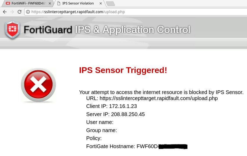
While using the Single Device Deployment architecture the firewall produced warning
Ri
pages for most test data:
ll
Fu
ns
ai
et
rR
ho
ut
,A
te
itu
st
In
NS
SA
In Single Interception with Parallel Distribution model, the TLS session between the
e
browser and the web server was intercepted and the unencrypted data was
Th
delivered to the designated firewall interfaces:
18
Firewall Config Snippet:
20
config firewall policy
edit 57
©
set name "PrivatetoLAMP"
set uuid 13a22fa8-d06d-51e7-b7ad-330e6f2e489a
set srcintf "Private"
set dstintf "virtualDMZ"
set srcaddr "all"
set dstaddr "LAMP Server"
set action accept
set schedule "always"
set service "ALL"
set utm-status enable
set ssl-mirror enable
set ssl-mirror-intf "VirtualSnort" "VirtualPigPen" "VirtualSquid"
set ips-sensor "Just One Rule"
set ssl-ssh-profile "SSLIntercept"
Chris Farrell, chrisf@iquest.net
© 2018 The SANS Institute Author retains full rights.ts
Looking under the Rock 33
gh
next
Ri
end
ll
Fu
ns
Monitoring systems detected and alerted on the test data just as the firewall had in Single
Device Deployment testing:
ai
et
rR
ho
ut
,A
te
More importantly, network traces taken from the security monitoring systems provided
itu
confirmation of clear-text delivery to each system:
st
In
NS
SA
e
Th
18
20
©
Chris Farrell, chrisf@iquest.net
© 2018 The SANS Institute Author retains full rights.ts
Looking under the Rock 34
gh
Ri
ll
Fu
ns
ai
et
rR
ho
ut
,A
te
itu
st
In
NS
SA
e
Th
18
20
©
Chris Farrell, chrisf@iquest.net
© 2018 The SANS Institute Author retains full rights.Last Updated: September 24th, 2020
Upcoming SANS Training
Click here to view a list of all SANS Courses
SANS October Singapore 2020 Singapore, SG Oct 12, 2020 - Oct 24, 2020 Live Event
SANS Community CTF , Oct 15, 2020 - Oct 16, 2020 Self Paced
SANS SEC504 Rennes 2020 (In French) Rennes, FR Oct 19, 2020 - Oct 24, 2020 Live Event
SANS SEC560 Lille 2020 (In French) Lille, FR Oct 26, 2020 - Oct 31, 2020 Live Event
SANS Tel Aviv November 2020 Tel Aviv, IL Nov 01, 2020 - Nov 06, 2020 Live Event
SANS Sydney 2020 Sydney, AU Nov 02, 2020 - Nov 14, 2020 Live Event
SANS Secure Thailand Bangkok, TH Nov 09, 2020 - Nov 14, 2020 Live Event
APAC ICS Summit & Training 2020 Singapore, SG Nov 13, 2020 - Nov 21, 2020 Live Event
SANS FOR508 Rome 2020 (in Italian) Rome, IT Nov 16, 2020 - Nov 21, 2020 Live Event
SANS Community CTF , Nov 19, 2020 - Nov 20, 2020 Self Paced
SANS Local: Oslo November 2020 Oslo, NO Nov 23, 2020 - Nov 28, 2020 Live Event
SANS Wellington 2020 Wellington, NZ Nov 30, 2020 - Dec 12, 2020 Live Event
SANS OnDemand OnlineUS Anytime Self Paced
SANS SelfStudy Books & MP3s OnlyUS Anytime Self PacedYou can also read