SMARC-sAL28 - USER GUIDE - Kontron
←
→
Page content transcription
If your browser does not render page correctly, please read the page content below
USER GUIDE
SMARC-sAL28
User Guide Rev. 1.1
Doc-ID: 1064-6120
// 1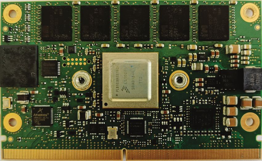
SMARC-sAL28 – User Guide Rev. 1.1

                  This page has been intentionally left blank

www.kontron.com                                                                              // 2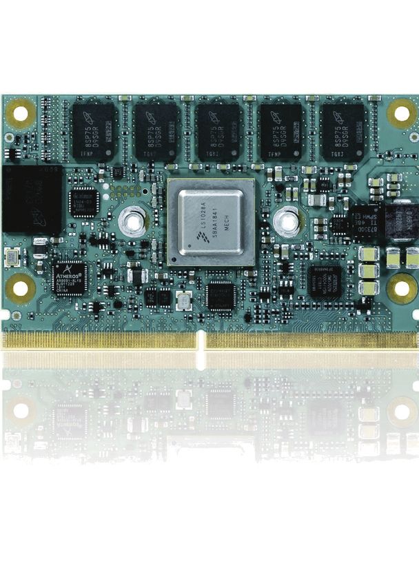
SMARC-sAL28 – User Guide Rev. 1.1
SMARC-SAL28 – USER GUIDE
Disclaimer
Kontron would like to point out that the information contained in this manual may be subject to alteration, particularly
as a result of the constant upgrading of Kontron products. This document does not entail any guarantee on the part
of Kontron with respect to technical processes described in the manual or any product characteristics set out in the
manual. Kontron assumes no responsibility or liability for the use of the described product(s), conveys no license or
title under any patent, copyright or mask work rights to these products and makes no representations or warranties
that these products are free from patent, copyright or mask work right infringement unless otherwise specified.
Applications that are described in this manual are for illustration purposes only. Kontron makes no representation or
warranty that such application will be suitable for the specified use without further testing or modification. Kontron
expressly informs the user that this manual only contains a general description of processes and instructions which
may not be applicable in every individual case. In cases of doubt, please contact Kontron.
This manual is protected by copyright. All rights are reserved by Kontron. No part of this document may be reproduced,
transmitted, transcribed, stored in a retrieval system, or translated into any language or computer language, in any
form or by any means (electronic, mechanical, photocopying, recording, or otherwise), without the express written
permission of Kontron. Kontron points out that the information contained in this manual is constantly being updated
in line with the technical alterations and improvements made by Kontron to the products and thus this manual only
reflects the technical status of the products by Kontron at the time of publishing.
Brand and product names are trademarks or registered trademarks of their respective owners.
©2021 by Kontron Europe GmbH
Kontron Europe GmbH
Gutenbergstraße 2
85737 Ismaning
Germany
www.kontron.com
// 3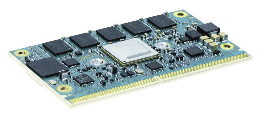
SMARC-sAL28 – User Guide Rev. 1.1

Revision History

 Revision      Brief Description of Changes                                  Date of Issue          Author
 1.0           Initial issue                                                 2020-January-20        hjs
 1.1           Word2016 issues                                               2021-March-31          hjs

Intended Use
THIS DEVICE AND ASSOCIATED SOFTWARE ARE NOT DESIGNED, MANUFACTURED OR INTENDED FOR USE OR RESALE
FOR THE OPERATION OF NUCLEAR FACILITIES, THE NAVIGATION, CONTROL OR COMMUNICATION SYSTEMS FOR
AIRCRAFT OR OTHER TRANSPORTATION, AIR TRAFFIC CONTROL, LIFE SUPPORT OR LIFE SUSTAINING APPLICATIONS,
WEAPONS SYSTEMS, OR ANY OTHER APPLICATION IN A HAZARDOUS ENVIRONMENT, OR REQUIRING FAIL-SAFE
PERFORMANCE, OR IN WHICH THE FAILURE OF PRODUCTS COULD LEAD DIRECTLY TO DEATH, PERSONAL INJURY, OR
SEVERE PHYSICAL OR ENVIRONMENTAL DAMAGE (COLLECTIVELY, "HIGH RISK APPLICATIONS").
You understand and agree that your use of Kontron devices as a component in High Risk Applications is entirely at
your risk. To minimize the risks associated with your products and applications, you should provide adequate design
and operating safeguards. You are solely responsible for compliance with all legal, regulatory, safety, and security
related requirements concerning your products. You are responsible to ensure that your systems (and any Kontron
hardware or software components incorporated in your systems) meet all applicable requirements. Unless
otherwise stated in the product documentation, the Kontron device is not provided with error-tolerance capabilities
and cannot therefore be deemed as being engineered, manufactured or setup to be compliant for implementation or
for resale as device in High Risk Applications. All application and safety related information in this document
(including application descriptions, suggested safety measures, suggested Kontron products, and other materials) is
provided for reference only.

                      Handling and operation of the product is permitted only for trained personnel within a work
                      place that is access controlled. Please follow the “General Safety Instructions” supplied with
                      the system.

                      You find the most recent version of the “General Safety Instructions“ online in the download
                      area of this product.

                                                                                                                  // 4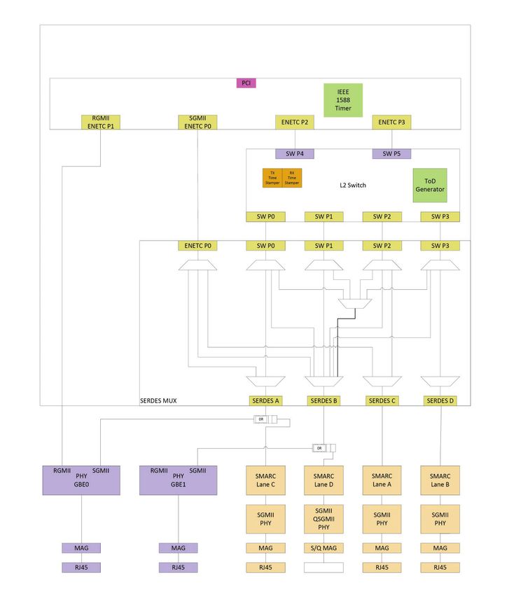
SMARC-sAL28 User Guide Rev. 1.1

Customer Support
Find Kontron contacts by visiting: http://www.kontron.com/support.

Terms and Conditions
Kontron warrants products in accordance with defined regional warranty periods. For more information about
warranty compliance and conformity, and the warranty period in your region, visit http://www.kontron.com/terms-
and-conditions.
Kontron sells products worldwide and declares regional General Terms & Conditions of Sale, and Purchase Order
Terms & Conditions. Visit http://www.kontron.com/terms-and-conditions.

For contact information, refer to the corporate offices contact information on the last page of this user guide or visit
our website CONTACT US.

Customer Support
Find Kontron contacts by visiting: https://www.kontron.de/support-and-services.

Customer Service
As a trusted technology innovator and global solutions provider, Kontron extends its embedded market strengths into
a services portfolio allowing companies to break the barriers of traditional product lifecycles. Proven product
expertise coupled with collaborative and highly-experienced support enables Kontron to provide exceptional peace
of mind to build and maintain successful products.
For more details on Kontron’s service offerings such as: enhanced repair services, extended warranty, Kontron
training academy, and more visit http://www.kontron.com/support-and-services/services.

Customer Comments
If you have any difficulties using this user guide, discover an error, or just want to provide some feedback, contact
Kontron support. Detail any errors you find. We will correct the errors or problems as soon as possible and post the
revised user guide on our website.

www.kontron.com                                                                                                     // 5
SMARC-sAL28 User Guide Rev. 1.1

Symbols
The following symbols may be used in this manual

                    DANGER indicates a hazardous situation which, if not avoided,
                    will result in death or serious injury.

                    WARNING indicates a hazardous situation which, if not avoided,
                    could result in death or serious injury.

                    NOTICE indicates a property damage message.

                    CAUTION indicates a hazardous situation which, if not avoided,
                    may result in minor or moderate injury.

                    Electric Shock!
                    This symbol and title warn of hazards due to electrical shocks (> 60 V) when touching
                    products or parts of products. Failure to observe the precautions indicated and/or prescribed
                    by the law may endanger your life/health and/or result in damage to your material.

                    ESD Sensitive Device!
                    This symbol and title inform that the electronic boards and their components are sensitive to
                    static electricity. Care must therefore be taken during all handling operations and inspections
                    of this product in order to ensure product integrity at all times.

                    HOT Surface!
                    Do NOT touch! Allow to cool before servicing.

                    Laser!
                    This symbol inform of the risk of exposure to laser beam and light emitting devices (LEDs)
                    from an electrical device. Eye protection per manufacturer notice shall review before
                    servicing.

                    This symbol indicates general information about the product and the user guide.
                    This symbol also indicates detail information about the specific product configuration.

                    This symbol precedes helpful hints and tips for daily use.

www.kontron.com                                                                                                  // 6
SMARC-sAL28 User Guide Rev. 1.1
For Your Safety
Your new Kontron product was developed and tested carefully to provide all features necessary to ensure its
compliance with electrical safety requirements. It was also designed for a long fault-free life. However, the life
expectancy of your product can be drastically reduced by improper treatment during unpacking and installation.
Therefore, in the interest of your own safety and of the correct operation of your new Kontron product, you are
requested to conform with the following guidelines.
High Voltage Safety Instructions
As a precaution and in case of danger, the power connector must be easily accessible. The power connector is the
product’s main disconnect device.
Warning
All operations on this product must be carried out by sufficiently skilled personnel only.
Electric Shock!
Before installing a non hot-swappable Kontron product into a system always ensure that
your mains power is switched off. This also applies to the installation of piggybacks. Serious
electrical shock hazards can exist during all installation, repair, and maintenance operations
on this product. Therefore, always unplug the power cable and any other cables which
provide external voltages before performing any work on this product.
Earth ground connection to vehicle’s chassis or a central grounding point shall remain
connected. The earth ground cable shall be the last cable to be disconnected or the first
cable to be connected when performing installation or removal procedures on this product.
Special Handling and Unpacking Instruction
ESD Sensitive Device!
Electronic boards and their components are sensitive to static electricity. Therefore, care
must be taken during all handling operations and inspections of this product, in order to
ensure product integrity at all times.
Do not handle this product out of its protective enclosure while it is not used for operational purposes unless it is
otherwise protected.
Whenever possible, unpack or pack this product only at EOS/ESD safe work stations. Where a safe work station is
not guaranteed, it is important for the user to be electrically discharged before touching the product with his/her
hands or tools. This is most easily done by touching a metal part of your system housing.
It is particularly important to observe standard anti-static precautions when changing piggybacks, ROM devices,
jumper settings etc. If the product contains batteries for RTC or memory backup, ensure that the product is not
placed on conductive surfaces, including anti-static plastics or sponges. They can cause short circuits and damage
the batteries or conductive circuits on the product.
www.kontron.com // 7SMARC-sAL28 User Guide Rev. 1.1
General Instructions on Usage
In order to maintain Kontron’s product warranty, this product must not be altered or modified in any way. Changes
or modifications to the product, that are not explicitly approved by Kontron and described in this User Guide or
received from Kontron’s Technical Support as a special handling instruction, will void your warranty.
This product should only be installed in or connected to systems that meet all necessary technical and specific
environmental requirements. This also applies to the operational temperature range of the specific board version,
which must not be exceeded. If batteries are present, their temperature restrictions must be taken into account.
In performing all necessary installation and application operations, only follow the instructions supplied by the
present User Guide.
Keep all the original packaging material for future storage or warranty shipments. If it is necessary to store or ship
the product then re-pack it in the same manner as it was delivered.
Special care is necessary when handling or unpacking the product. See Special Handling and Unpacking Instruction.
Quality and Environmental Management
Kontron aims to deliver reliable high-end products designed and built for quality, and aims to complying with
environmental laws, regulations, and other environmentally oriented requirements. For more information regarding
Kontron’s quality and environmental responsibilities, visit http://www.kontron.com/about-kontron/corporate-
responsibility/quality-management.
Disposal and Recycling
Kontron’s products are manufactured to satisfy environmental protection requirements where possible. Many of
the components used are capable of being recycled. Final disposal of this product after its service life must be
accomplished in accordance with applicable country, state, or local laws or regulations.
WEEE Compliance
The Waste Electrical and Electronic Equipment (WEEE) Directive aims to:
Reduce waste arising from electrical and electronic equipment (EEE)
Make producers of EEE responsible for the environmental impact of their products, especially when the product
become waste
Encourage separate collection and subsequent treatment, reuse, recovery, recycling and sound environmental
disposal of EEE
Improve the environmental performance of all those involved during the lifecycle of EEE
Environmental protection is a high priority with Kontron.
Kontron follows the WEEE directive
You are encouraged to return our products for proper disposal.
www.kontron.com // 8SMARC-sAL28 User Guide Rev. 1.1 Table of Contents Symbols........................................................................................................................................................................................................................6 Table of Contents .....................................................................................................................................................................................................9 List of Tables ............................................................................................................................................................................................................ 10 List of Figures ...........................................................................................................................................................................................................11 1/ Introduction ................................................................................................................................................................................................ 12 2/ Description ................................................................................................................................................................................................. 13 2.1. SMARC™ Computer-on-Modules ............................................................................................................................................................ 13 2.2. Standard Variants ..........................................................................................................................................................................................14 2.3. Network Configuration Options................................................................................................................................................................14 2.4. SMARC-sAL28 Feature Set ......................................................................................................................................................................... 16 3/ System Specifications ............................................................................................................................................................................ 17 3.1. Component Main Data .................................................................................................................................................................................. 17 3.2. Environmental Conditions ..........................................................................................................................................................................18 3.3. Functional Block Diagram .......................................................................................................................................................................... 20 4/ Board and Connectors............................................................................................................................................................................ 21 4.1.1. Connectors ..................................................................................................................................................................................................... 21 4.2. Mainboard view and I/O locations .......................................................................................................................................................... 21 4.3. Mechanical Drawings .................................................................................................................................................................................. 23 5/ Pin Definitions .......................................................................................................................................................................................... 24 5.1. Processor Support ......................................................................................................................................................................................... 24 5.2. System Memory Support ........................................................................................................................................................................... 24 5.3. SPI NOR Flash.................................................................................................................................................................................................. 24 5.4. I2C Buses .......................................................................................................................................................................................................... 25 5.5. SPI Interfaces .................................................................................................................................................................................................. 25 5.6. eMMC NAND Flash Memory ...................................................................................................................................................................... 25 5.7. SD-Card Interface .......................................................................................................................................................................................... 26 5.8. SerDes Interfaces.......................................................................................................................................................................................... 27 5.9. CAN Interfaces ................................................................................................................................................................................................ 29 5.10. USB Interfaces .............................................................................................................................................................................................. 29 5.10.1. USB OTG Port .............................................................................................................................................................................................. 29 5.11. UART Interfaces ............................................................................................................................................................................................ 29 5.12. Ethernet Interfaces ..................................................................................................................................................................................... 30 5.12.1. GBE0 ............................................................................................................................................................................................................... 30 5.12.2. GBE1 ............................................................................................................................................................................................................... 30 5.12.3. MDIO .............................................................................................................................................................................................................. 30 5.12.4. QSGMII .......................................................................................................................................................................................................... 30 5.13. Audio Interfaces ............................................................................................................................................................................................ 31 5.14. SMARC Connector ........................................................................................................................................................................................ 31 5.15. Pinout of SMARC sAL28 Connector....................................................................................................................................................... 32 5.15.1. Pinout of SMARC sAL28 Topside Connector................................................................................................................................... 32 5.15.2. Pinout of SMARC sAL28 Bottom Side Connector ......................................................................................................................... 36 5.16. JTAG Debug connector ............................................................................................................................................................................... 40 6/ Configuration .............................................................................................................................................................................................41 6.1. Boot Mode..........................................................................................................................................................................................................41 6.2. Configurable Watchdog ...............................................................................................................................................................................41 6.3. RTC current consumption ...........................................................................................................................................................................41 6.4. Power Control ................................................................................................................................................................................................ 42 6.4.1. Power Supply ............................................................................................................................................................................................... 42 www.kontron.com // 9
SMARC-sAL28 User Guide Rev. 1.1

6.4.2. Power Button (POWER_BTN#) ............................................................................................................................................................ 42
6.4.3. Power Management Signals ................................................................................................................................................................. 42
6.4.4. Battery Control Signals ........................................................................................................................................................................... 43
7/           Installation and Setup Procedures ...................................................................................................................................................44
7.1. Building BSP images (rootfs, kernel, device tree) .............................................................................................................................44
7.2. Deploying created images to SD card or USB flash/disk and booting from it ...................................................................... 45
7.3. Booting from NFS server ............................................................................................................................................................................ 46
7.4. Deploying created images to on-board eMMC and booting from it ......................................................................................... 46
8/           Implementation Notes ..........................................................................................................................................................................48
8.1. GPIO .....................................................................................................................................................................................................................48
8.2. UART................................................................................................................................................................................................................... 49
8.3. PCI ....................................................................................................................................................................................................................... 50
8.4. I2C Buses .......................................................................................................................................................................................................... 50
8.5. SPI Buses .......................................................................................................................................................................................................... 50
8.6. Watchdog .......................................................................................................................................................................................................... 51
8.7. CAN ...................................................................................................................................................................................................................... 51
8.8. Video Output (DP and LVDS) ...................................................................................................................................................................... 51
8.9. Fan Monitoring and Control ...................................................................................................................................................................... 52
8.10. Thermal Management .............................................................................................................................................................................. 52
8.10.1. Heatspreader and Cooling Solutions ................................................................................................................................................ 52
8.10.2. Operating with Kontron Heatspreader Plate (HSP) Assembly .............................................................................................. 52
8.10.3. Operating without Kontron Heatspreader Plate Assembly .................................................................................................... 53
8.11. TSN Switch...................................................................................................................................................................................................... 53
9/           Bootloader Operation ............................................................................................................................................................................ 54
9.1. Copyrights and Licensing of U-Boot ....................................................................................................................................................... 54
9.2. Bootloader Quickstart ................................................................................................................................................................................. 54
9.3. Bootloader Commands ............................................................................................................................................................................... 55
9.4. Kontron Bootloader Command Extensions ........................................................................................................................................ 55
9.4.1. kboardinfo - Kontron Board Information.......................................................................................................................................... 56
9.4.2. Wdt – CPU Watchdog Control............................................................................................................................................................... 56
9.5. Bootloader Environment ............................................................................................................................................................................ 56
9.6. Bootloader Environment Update ............................................................................................................................................................ 57
9.7. Bootloader Mass Storage Support ......................................................................................................................................................... 58
9.7.1. QSPI flash....................................................................................................................................................................................................... 58
9.7.2. SD Card and eMMC Devices ................................................................................................................................................................... 58
9.7.3. USB Storage Device ................................................................................................................................................................................... 58
9.8. Bootloader File System Support ............................................................................................................................................................. 58
9.9. Bootloader Network Support ................................................................................................................................................................... 59
9.10. Bootloader Boot Counter ......................................................................................................................................................................... 59
9.11. U-boot Files for the Kontron SMARC sAL28 Module on Github.com ....................................................................................... 59
10/          Technical Support ................................................................................................................................................................................... 60
10.1. Warranty ......................................................................................................................................................................................................... 60
10.2. Returning Defective Merchandise ........................................................................................................................................................ 60
List of Acronyms .................................................................................................................................................................................................... 62
About Kontron – Member of the S&T Group............................................................................................................................................... 63

List of Tables
Table 1: Product Numbers of SMARC-sAL28 ...............................................................................................................................................14
Table 2: Product Variants of SMARC-sAL28 ................................................................................................................................................14
www.kontron.com                                                                                                                                                                                                            // 10
SMARC-sAL28 User Guide Rev. 1.1

Table 3: SMARC-sAL28 Feature Set ................................................................................................................................................................ 16
Table 4: Component Main Data ........................................................................................................................................................................ 17
Table 5: Environmental Conditions .................................................................................................................................................................18
Table 6: Connectors of SMARC-sAL28 ........................................................................................................................................................... 21
Table 7: Processor Support ............................................................................................................................................................................... 24
Table 8: DDR3L memory options ..................................................................................................................................................................... 24
Table 9: SPI NOR Flash......................................................................................................................................................................................... 24
Table 10: I2C Buses ............................................................................................................................................................................................... 25
Table 11: SPI Buses ................................................................................................................................................................................................ 25
Table 12: eMMC NAND Flash ............................................................................................................................................................................. 26
Table 13: SD-Card Interface ............................................................................................................................................................................... 26
Table 14: SerDes Interfaces ............................................................................................................................................................................... 27
Table 15: CAN Interfaces ..................................................................................................................................................................................... 29
Table 16: USB Interfaces ..................................................................................................................................................................................... 29
Table 17: UART Interfaces................................................................................................................................................................................... 29
Table 18: Network variants ................................................................................................................................................................................ 30
Table 19: MDIO Interfaces .................................................................................................................................................................................. 30
Table 20: Audio Interface .................................................................................................................................................................................... 31
Table 21: Pinout of SMARC sAL28 Topside Connector ............................................................................................................................ 32
Table 22: Pinout of SMARC sAL28 Bottom Side Connector................................................................................................................... 36
Table 23: JTAG Debug connector ..................................................................................................................................................................... 40
Table 24: Boot Options on the carrier board ...............................................................................................................................................41
Table 25: Maximum current consumption of RTC .....................................................................................................................................41
Table 26: Power Supply Specifications ......................................................................................................................................................... 42
Table 27: GPIO .........................................................................................................................................................................................................48
Table 28: Heatspreader Test Temperature Specifications ................................................................................................................... 53
Table 29: Bootloader Command Extensions .............................................................................................................................................. 56
Table 30: Standard Environment Variables ................................................................................................................................................ 57

List of Figures
Figure 1: Half-size Card with SMARC interface ........................................................................................................................................... 13
Figure 2: Block Diagram ...................................................................................................................................................................................... 20
Figure 3: Top View .................................................................................................................................................................................................. 21
Figure 4: Bottom View ......................................................................................................................................................................................... 22
Figure 5: Dimensions of SMARC-sAL28 ........................................................................................................................................................ 23
Figure 6: Thickness from side view ................................................................................................................................................................ 23
Figure 7: SerDes Interface Matrix in LS1028A with SMARC PCIe Lanes Connections ................................................................. 28
Figure 8: 314-pin SMARC Connector, .............................................................................................................................................................. 31

www.kontron.com                                                                                                                                                                                                    // 11
SMARC-sAL28 User Guide Rev. 1.1

1/ Introduction
This manual describes the Smart Mobility Architecture (SMARC) sAL28 (NXP LS1028) board. The Advanced RISC
Machines (ARM) based module is equipped with a NXP i.MX7 processor. The dual core SoC take advantage of the
optimized power consumption and performance ratio.

The use of this Users Guide implies a basic knowledge of PC hard- and software. This manual is focussed on
describing the special features and is not intended to be a standard PC textbook. New users are recommended to
study the short installation procedure stated in the following chapter before switching on the power.
All configuration and setup of the CPU board is either done automatically or manually by the user via the BIOS setup
menus.
Latest revision of this manual, datasheet, BIOS, drivers and BSP’s (Board Support Packages) can be downloaded
from Kontron Web Page.

www.kontron.com                                                                                                  // 12
SMARC-sAL28 User Guide Rev. 1.1
2/ Description
The SMARC-sAL28 is a SMARC half-size module using the NXPs LS1028 processor with dual core ARM. It is designed
on the latest SMARC 2.0 specification. The SMARC-sAL28 is a highly integrated, embedded computer board
incorporating the edge technology with a dual core SoC from NXP to take advantage of the very optimized power
consumption/performance ratio. Due to the integrated Time-Sensitive Networking (TSN) capabilities of the LS1028
and the integrated 4-port Ethernet switch, this board will allow to build very cost effective TSN capable Ethernet
gateways for greenfield and brownfield applications.
Figure 1: Half-size Card with SMARC interface
2.1. SMARC™ Computer-on-Modules
The SMARC™ standard was developed especially for new modules with ARM- and SoC-processors. Boards with this
interfaces are characterized by the extremely flat form factor. The SMARC or MXM 3.0 connector comes with 314
pins and a construction height of just 4.3 millimeters. The connector is also available in a shock- and vibration-
resistant version for rough environmental conditions.
Furthermore, the standard integrates dedicated interfaces for the latest ARM, x86 and SoC processors like LVDS,
24-bit RGB and HDMI support. OEMs profit from minimized design effort and low Bill of Material (BoM) costs.
SMARC™ defines two different module sizes in order to offer a high level of flexibility regarding different
mechanical requirements.
Main characteristics of the SMARC-sAL28 are:
Dual-Core Cortex A-72 on a SMARC short size form factor
Based on LS1028 from NXP – one SKU with configurable Serialiser/Deserialiser SERDES lines (5 W target
TDP)
Up to 4 GB DDR3L non-ECC and ECC memory down, ECC as default, 8 GbE as option
One PCIe line can be used as QSGMII port to drive 4x 1 GB TSN capable Ethernet ports
3D GPU
DP support (default)
LVDS Display support (resistor option)
Alternative eDP (resistor option)
2x Gigabit Ethernet, Wake on LAN (WoL) support, TSN capable
Support for Audio and common features (SPI, I2C, SMB etc.)
Chip integrated security solution support
Full industrial grade temp. range E2 (-40°C up to +85°C) for standard SKUs, commercial version possible
eMMC flash onboard
Optional APPROTECT (security chip) support on request, more information under
https://www.kontron.de/products/solutions/security/approtect.html
www.kontron.com // 13SMARC-sAL28 User Guide Rev. 1.1
2.2. Standard Variants
Following standard variants are available:
Table 1: Product Numbers of SMARC-sAL28
Product Number Board Description
51011-0208-13-2-2 SMARC-sAL28, LS1028 SMARC with NXP LS1028, 1,3 GHz dual core; 2 GB
dual, 2E/8S, NW 2 DDR3L ECC, 8 GB eMMC SLC, Networkconfig 2, 2x PCIe,
audio, DP, industrial temperature
51011-0408-13-2-3 SMARC-sAL28, LS1028 SMARC with NXP LS1028, 1,3 GHz dual core; 4 GB
dual, 4E/8S, NW 3 DDR3L ECC, 8 GB eMMC SLC, Networkconfig 3, 2x PCIe,
audio, DP, industrial temperature
51011-0432-13-2-4 SMARC-sAL28, LS1028 SMARC with NXP LS1028, 1,3 GHz dual core; 4 GB
dual, 4E/32S, NW 4 DDR3L ECC, 32 GB eMMC SLC, Networkconfig 4, 2x
PCIe, no audio, DP, industrial temperature
2.3. Network Configuration Options
Table 2: Product Variants of SMARC-sAL28
Variant Description
Network Variant 1 Available on customer request
(Single PHY module, optional) SMARC with NXP LS1028, 1.3 GHz dual core; 2 GB DDR3L ECC,
8 GB eMMC SLC, DP, industrial temperature
GBE0 PHY connected to RGMII (L0) to CPU (not TSN capable)
GBE1 not connected on module, GBE1 could be used on custom
carrier to support 2.5 GBE
no audio
"TSN" variant, although GBE0 is not TSN capable, thus the TSN
function needs a TSN carrier.
TSN-on-carrier (board provides the 4 TSN capable ports on
PCIe D by QSGMII lane)
4 lanes available towards the carrier
Possible PCIe options (lane AB/CD), one of
2x PCIe x1
1x PCIe x1 + 1x SATA
1x PCIe x2 + 1x PCIe x1
2x PCIe x2 (no TSN-On-Carrier)
1x PCIe x4, with custom carrier, because
special lane order (CDAB instead of ABCD),
(no TSN-On-Carrier)
Network Variant 2 SMARC with NXP LS1028, 1.3 GHz dual core; 2 GB DDR3L ECC,
(Dual TSN port module) 8 GB eMMC SLC, DP, industrial temperature
GBE0 PHY connected to SGMII (L0) to the internal switch
GBE1 PHY connected to SGMII (L1) to the internal switch
no direct network operation without switch up and running
Dual port TSN Endpoint (no need of additional PHYs on Carrier)
Audio
no QSGMII lane
Possible PCIe options (lane A/B), one of
2x PCIe x1
www.kontron.com // 14SMARC-sAL28 User Guide Rev. 1.1
Variant Description
1x PCIe x2
1x PCIe x1 + 1x SATA
Network Variant 3 SMARC with NXP LS1028, 1.3 GHz dual core; 4 GB DDR3L ECC,
(Single PHY module) 8 GB eMMC SLC, DP, industrial temperature
GBE0 PHY connected to SGMII (L0) to CPU (TSN capable)
GBE1 PHY not connected, GBE1 could be used on custom carrier
to support 2.5 GBE
5 ports in total
audio
TSN-on–Carrier (board provides the 4 TSN capable ports on
PCIe D by QSGMII lane)
Possible PCIe options (lane A/B), one of
2x PCIe x1
1x PCIe x2
1x PCIe x1 + 1x SATA
Network Variant 4 SMARC with NXP LS1028, 1.3 GHz dual core; 4 GB DDR3L ECC,
(Dual PHY module) 32 GB eMMC SLC, DP, industrial temperature
GBE0 PHY connected to SGMII (L0) to CPU (TSN capable)
GBE0 PHY could be connected to switch
GBE1 connected to RGMII to CPU
6 ports in total
no audio
TSN-on–Carrier (board provides the 4 TSN capable ports on
PCIe D by QSGMII lane)
Possible PCIe options (lane A/B), one of
2x PCIe x1
1x PCIe x2
1x PCIe x1 + 1x SATA
Following accessories are available:
SMARC 2.0 Evaluation Carrier
SMARC Starter Kit
KBOX-A-230-LS, including a SMARC-sAl28 Module and a S1914 Carrier exposing the TSN switch Interfaces
www.kontron.com // 15SMARC-sAL28 User Guide Rev. 1.1
2.4. SMARC-sAL28 Feature Set
Table 3: SMARC-sAL28 Feature Set
SMARC™ Feature SMARC™ SMARC-sAL28 Description
specification Specification Feature support
Maximum Number
Possible
LVDS Display 2 2 LVDS option disabled
support Default option is DP
CSI Camera 2 No
support
USB Interface 6x USB 2.0 6x USB 2.0 USB0 without OTG support
with 2x USB 3.0 with 1x USB 3.0 USB3 with USB 3.0 and OTG support
included included
PCIe Interface 4 2 maximum 2 PCIe controller
GbE Interface 2 Yes
SDIO Interface 1 Yes
SPI Interface 2 Yes Each bus with one chip select at
standard modules
I2S Interface 2 1
I2C Interface 5 3 I2C_PM, I2C_GP, I2C_LCD
CAN 2 2 Second CAN interface as option with
abandonment of one I2C interface
www.kontron.com // 16SMARC-sAL28 User Guide Rev. 1.1
3/ System Specifications
3.1. Component Main Data
The table below summarizes the features of the motherboard.
Table 4: Component Main Data
SMARC-sAL28
Form factor Smart Mobility Architecture (SMARC) Hardware with 82 mm x 50 mm, max. thickness
6 mm
Processor NXP LS28 Layerscape SoC 1.3 GHz, 488 balls FC-BGA, 17x17 mm, 28 nm CMOS
Memory DDR3L memory down. Maximum DDR3L memory size 8 GB.
Standard products with 2 GB and 4 GB are available.
For cost reductions lower memory sizes are possible.
Boot Flash 2 MB to 32 MB SPI NOR flash
Bootloader/BIOS U-Boot Bootloader, Flash for Bootloader connected on SPI1(eSPI).
embedded 8 GB pSLC and 32 GB pSLC on standard products
Multimedia Card option for up to 64GB pSLC
(eMMC)
EEPROM 24C32, 4k x 8 (32 kbit)
Temperature Thermal Monitoring Unit (TMU) with +/- 5°C accuracy (CPU internal)
Monitoring Thermal sensor measurement temperature range is 0°C to 125°C.
Onboard Controllers
Ethernet Controller 2x 1 GBE PHY Qualcomm AR8031-AL, WOL support
1st PHY via SGMII or RGMII BOM option
2nd PHY as BOM option via SGMII
Watchdog CPU internal watchdog
CPLD watchdog for WDT_TIME_OUT#
RTC High accuracy (+/-3 ppm)
Low power consumption: current consumption typical below 1 μA
USB HUB 7 port USB HUB Microchip USB2517I
Display bridge Optional: Display Port to LVDS converter PTN3460I
System CPLD Intel/Altera MAX V 5M570Z
Management
Controller
Security Optional: APPROTECT Key 1504-03 connected via USB, no SPI connection
Power CPLD controls payload power down state
management
Operating System Linux Yocto
Support Buildroot (https://github.com/kontron/buildroot-external-smarc-sal28)
other Operating Systems on customer request
Interfaces via Smarc I/O
USB USB0, USB1, USB2, USB3, USB4, USB5: USB Standard 2.0
USB3: USB Standard 3.1 GEN1 with OTG support
PCIe 4x configurable SERDES lines. Line A and B always present. C and D either used for on
module LAN PHYs or as SGMII/XGMII on the carrier (resistor BOM options)
Up to 2x PCIe controller
Audio I2S0
www.kontron.com // 17SMARC-sAL28 User Guide Rev. 1.1
Display Display port as standard option, FHD (1920x1080) and UHD (3840x2160)
Optional: Dual channel LVDS up to 1920x1200 with NXP PTN3460I
SD-Card 1x SDIO
UART SER0 with RTC/CTS hardware flow control to CPU
SER1, SER2 RX/TX
Serial Peripheral One chip select available at standard module
Interface (SPI0) Optional: second chip select possible with abandonment of USB3 power control from CPU
eSPI/SPI1 XSPI_A with CS0#, CS1# – CS0# to module SPI-flash (default)
Optional: CS0# to edge Connector (for Carrier uboot booting without SPI flash on module)
ALERT0#, ALERT1#, SPI_RESET# from CPLD
GPIO 12 GPIOs
CAN 1x CAN
Optional: Second CAN interface with abandonment of one I2C interface
Power
Consumption Maximum Power consumption of the board is estimated to 15 W
Input Voltage Wide range VCC 3.0 V to 5.25 V
vripple_p-p (0-20 MHz) = 200 mV 0.1 – 20 ms input voltage rise ramp to 10% nominal VCC
Miscellaneous
Panel Signal Display Port
Optional: dual channel LVDS or eDP
Features On 2x PCIe x2 or 1x PCIe x4 configuration
Request eMMC 5.1 Flash onboard up to 64 GByte pSLC, up to 128 GByte (MLC)
Dual Channel LVDS or eDP instead of DP
3.2. Environmental Conditions
Table 5: Environmental Conditions
Operating industrial: -40°C to 85°C
relative humidity (non-condensing) 10% to 93% at 40°C (acc. to IEC 60068-2-78)
Storage industrial grade: -40°C to +85°C
relative humidity (non-condensing) 10 % to 93 % at 40°C (acc. to IEC 60068-2-78)
Electromagnetic according to
Compatibility EN 55032:2015 Electromagnetic compatibility of multimedia equipment - Emission
(EMC) requirements (CISPR 32:2015); German version EN 55032:2015
EN 55024:2010 + A1:2015 Information technology equipment - Immunity
characteristics - Limits and methods of measurement (CISPR 24:2010 + Cor.:2011 +
A1:2015); German version EN 55024:2010 + A1:2015
CE CE according to
EN62368-1:2014 + AC:2017
EN610000-6-3:2007 + A1:2011
CISPR 32: Edition 1.0 2012-01, class B, 1-6 GHz
EN55032:2015
EN55024:2010 + A1:2015
UL according to IEC 62368-1 (ed.2)
Shock Pulse: half sinus
Period: 11 ms
Acceleration: 15 g
Cycles: three shocks per axis, three axes
www.kontron.com // 18SMARC-sAL28 User Guide Rev. 1.1
Vibration Sinus from 10 Hz -3000 Hz
Amplitude: 10 Hz-57,6 Hz: +/- 0,15 mm
Acceleration: 57,6 Hz – 3000Hz: 2 g
Cycles: 10 per axis, three axes
Theoretical MTBF estimated 10 years at 40°C
RoHS II Compliance The product is RoHS II compliant
www.kontron.com // 19SMARC-sAL28 User Guide Rev. 1.1
3.3. Functional Block Diagram
The block diagram shows all available interfaces on the sAL28 module.
Figure 2: Block Diagram
PCIE_A_CLK 100MHz w/o SSC 100MHz w/o SSC SYSCLK
JTAG JTAG chain
PCIE_B_CLK 100MHz w/o SSC 100MHz w/ SSC SD1_REF_CLK1 DDR3L
DDR3L
PCIE_C_CLK 100MHz w/o SSC 125MHz/156.25MHz w/o SSC SD1_REF_CLK2 DDR3 + ECC x36 memory
memorydown
down
USB hub 24MHz 27MHz w/o SSC DP_REF_CLK
Clock generator
5 devices x8
5 x8 devices
0R TAMPER
Display port 1.3 and eDP 1.4 PCIe 3.0/SATA Lane D
I2C[1] PCIe 3.0/SGMII Lane C
JTAG chain
I2C_LOCAL
0R
JTAG chain NXP LS1028A
cfg[3:0]3 PCIe 3.0/QSGMII/SGMII Lane B
CPLD
JTAG chain
PCIe 3.0/10G-SXGMII/SGMII Lane A JTAG header
I2C[4] / FLEXCAN[2] TAG connect
TD1 (Thermal Diode)
I2C[5]
XSPI1_A and CS1#
eDP to
XSPI1_A CS0#
SPI[3] (CS0#)
LVDS
1588/GPIO/
USB[1] 3.0 OTG
FLEXCAN[1]
MDC/MDIO
DUART[1:2]
RCW 0x50
LPUART[2]
RGMII/SAI
EEPROM
EEPROM
GP 0x50
eSDHC1
Power
eSDHS2
USB[2] 2.0
SAIx
0R 0R
0R
x8
0R
RTC
CS# 0R
boot flash
SPI NOR
eMMC
I2C_LOCAL
x4
USB0 USB-up
USB HUB
0R
USB1
USB2
USB3
USB4
USB5
USB6
0R 1G 1G
0R
WIBU PHY PHY
Key
SER[1],SER[3]
CAN[0]
DP
LVDS0/eDP
LVDS1
I2C_LCD
GPIOs
I2C_PM
I2C_GP
USB3
USB0
USB1
USB2
USB5
USB4
eSPI/SPI1
SPI0
SER[0]
I2S0
SDIO Card
GPIOs
GBE0
GBE1
PCIe A
PCIe B
PCIe C
RSVD
PCIe D
SATA
BOOT_SEL
SYSTEM
VDD_RTC_3V0
CAN[1]
VDD_IN_5V0
SMARC 2.0 pinout connector
Standard
Connector Option
component V2.02
www.kontron.com // 20SMARC-sAL28 User Guide Rev. 1.1
4/ Board and Connectors
4.1.1. Connectors
Table 6: Connectors of SMARC-sAL28
Connector Function Remark
SMARC Central Interface Mating connector: SMARC 2.0 (MXM3)
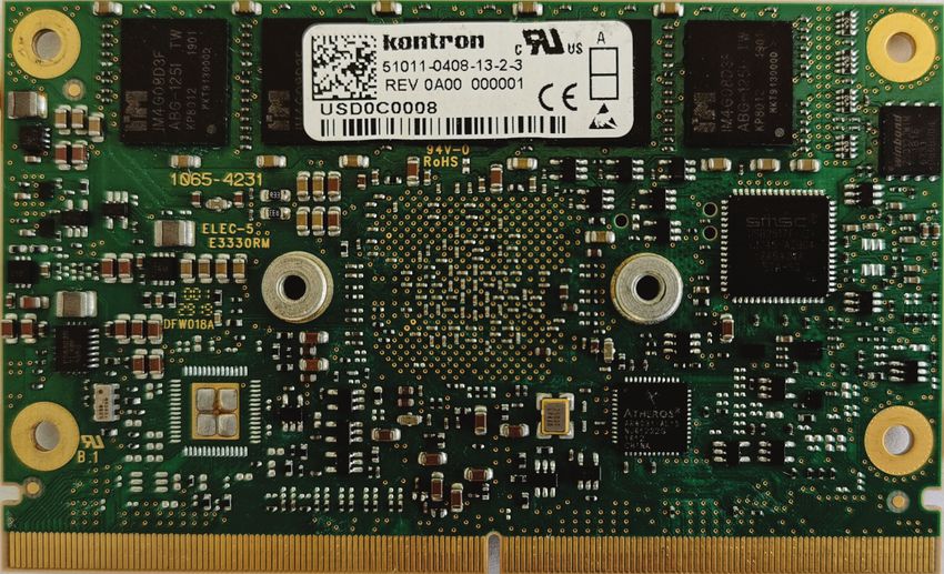
4.2. Mainboard view and I/O locations
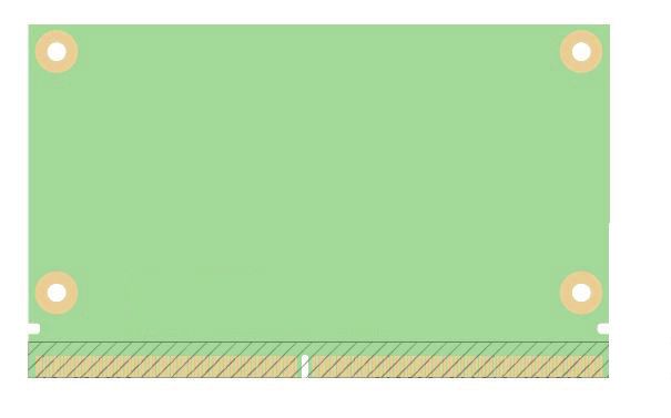
Figure 3: Top View 2
1. SMARC 2.0 module connector 1
2. Debug connector
www.kontron.com // 21SMARC-sAL28 User Guide Rev. 1.1
Figure 4: Bottom View 3
3. Product label
www.kontron.com // 22You can also read