Spider Web-Inspired Lightweight Membrane-Type Acoustic Metamaterials for Broadband Low-Frequency Sound Isolation - ResearchGate
←
→
Page content transcription
If your browser does not render page correctly, please read the page content below

Article

Spider Web-Inspired Lightweight Membrane-Type Acoustic
Metamaterials for Broadband Low-Frequency Sound Isolation
Heyuan Huang 1,2, Ertai Cao 1, Meiying Zhao 1, Sagr Alamri 3 and Bing Li 1,*

                                         1 School of Aeronautics, Northwestern Polytechnical University, Xi'an 710072, China;
                                           huangheyuan@nwpu.edu.cn (H.H.); caoertai@live.cn (E.C.); zhaomeiying@nwpu.edu.cn (M.Z.)
                                         2 Aircraft Strength Research Institute, Aviation Industries of China, Xi'an 710072, China

                                         3 Department of Mechanical Engineering, College of Engineering, King Khalid University, PO Box 394,

                                           Abha 61421, Saudi Arabia; salamri@kku.edu.sa
                                         * Correspondence: bingli@nwpu.edu.cn

                                         Abstract: Membrane-type acoustic metamaterial (MAM) has exhibited superior sound isolation
                                         properties, as well as thin and light characteristics. However, the anti-resonance modes of tradi-
                                         tional MAMs are generated intermittently in a wide frequency range causing discontinuities in the
                                         anti-resonance modes. Achieving broadband low-frequency sound attenuation with lightweight
                                         MAM design is still a pivotal research aspect. Here, we present a strategy to realize wide sound-
                                         attenuation bands in low frequency range by introducing the design concept of bionic configuration
                                         philosophy into the MAM structures. Built by a polymeric membrane and a set of resonators, two
                                         kinds of MAM models are proposed based on the insight of a spider web topology. The sound at-
                                         tenuation performance and physical mechanisms are numerically and experimentally investigated.
                                         Multi-state anti-resonance modes, induced by the coupling of the bio-inspired arrangement and the
Citation: Huang, H.; Cao, E.; Zhao,      host polymer film, are systematically explored. Significant sound attenuation is numerically and
M.; Alamri, S.; Li, B. Spider            experimentally observed in both the lightweight bio-inspired designs. Remarkably, compared with
Web-Inspired Lightweight                 a traditional MAM configuration, a prominent enhancement in both attenuation bandwidth and
Membrane-Type Acoustic                   weight-reduction performance is verified. In particular, the bio-inspired MAM Model I exhibits a
Metamaterials for Broadband              similar isolation performance as the reference model, but the weight is reduced by nearly half. The
Low-Frequency Sound Isolation.           bio-inspired Model II broadens the sound attenuation bandwidth greatly; meanwhile, it retains a
Polymers 2021, 13, 1146.                 lighter weight design. The proposed bio-inspired strategies provide potential ways for designing
https://doi.org/10.3390/
                                         sound isolation devices with both high functional and lightweight performance.
polym13071146

                                         Keywords: membrane-type acoustic metamaterials; bio-inspired structures; polymeric membrane;
Academic Editor: F.X. Espinach
                                         anti-resonance; low-frequency sound isolation; sound transmission loss
Received: 10 March 2021
Accepted: 29 March 2021
Published: 2 April 2021
                                         1. Introduction
Publisher’s Note: MDPI stays neu-             Ever-increasing requirements and higher demands for noise and vibration suppres-
tral with regard to jurisdictional       sion have attracted abundant effort to design novel structures and materials that are light-
claims in published maps and insti-      weight, yet with exceptional sound isolation/attenuation performance. However, achiev-
tutional affiliations.
                                         ing low-frequency noise isolation in lightweight structures is still an existing challenge,
                                         which lies in the fact of the mass law that poor sound absorption performance correspond-
                                         ing to lightweight design [1]. Traditional noise suppression approaches mostly adopt in-
                                         creasing structural size or weight to improve the blocking and attenuation effects on air-
Copyright: © 2021 by the authors.
                                         borne sound. However, traditional noise barriers, such as rubber, felt, sponge, etc., do not
Licensee MDPI, Basel, Switzerland.
                                         meet the volume or performance requirements of modern advanced engineering for
This article is an open access article
distributed under the terms and con-
                                         highly efficient noise isolation, especially in low-frequency range, due to the structural
ditions of the Creative Commons At-      limitation to the long wavelength [2–4].
tribution (CC BY) license (http://cre-        Recently, the concept of acoustic metamaterials has opened a new route to low-fre-
ativecommons.org/licenses/by/4.0/).      quency noise isolation with compact and lightweight structures, which can realize unique

Polymers 2021, 13, 1146. https://doi.org/10.3390/polym13071146                                                   www.mdpi.com/journal/polymers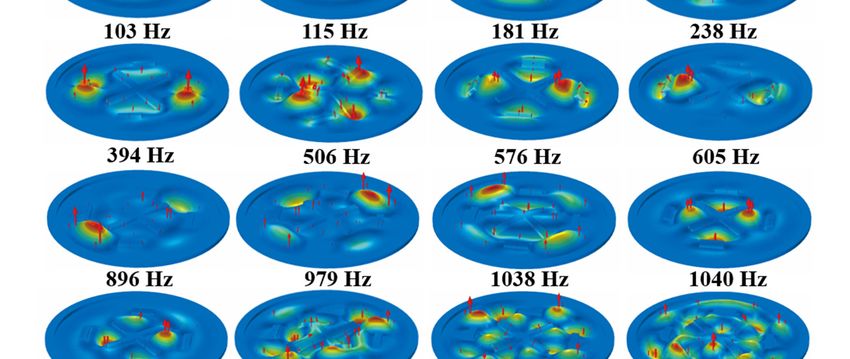
Polymers 2021, 13, 1146                                                                                          2 of 18

                          bandgap effects for effectively blocking wave propagation at the corresponding frequen-
                          cies based on locally resonant behaviors [5–7]. Such artificial structures have realized a
                          flurry of abnormal dynamic properties, including single/double negative/zero mass-den-
                          sity or modulus etc. [8–15], relying on engineered subwavelength microstructures rather
                          than the chemical compositions. A rich variety of extraordinary acoustic wave manipula-
                          tions, such as negative refraction [13,16], acoustic cloaking [16], unidirectional transmis-
                          sion [17] and so forth, have been enabled by such an innovative design philosophy. Vari-
                          ous types of local-resonance-based acoustic metamaterials with binary/multi-phase mate-
                          rials [2–4,15,18–20] have been proposed and developed for noise attenuation since the first
                          design built by Liu et al by using rubber-coated spheres for low-frequency bandgaps [5].
                          However, most of the early-developed acoustic metamaterials are still constrained by the
                          overall structural weight, heavy resonators and narrow working bandwidth. Significant
                          noise suppression within broadband, low-frequency range is still hard to be achieved by
                          using lightweight structural designs.
                                 Excitingly, as an emerging design fashion, a polymer film or thin plate-like acoustic
                          metamaterial, with a strong structural sound-solid synthesis effect, has demonstrated
                          great potential for prominent noise insulation, yet fulfilling lightweight demands [4,21].
                          Yang et al. [21] proposed the pioneering membrane-type metamaterial (MAM) in 2008,
                          which possesses negative effective mass in the low frequency region. After that, research-
                          ers have further developed a series of lightweight membrane-type acoustic metamaterials
                          (MAMs) and explored their excellent performance on low-frequency noise attenuation
                          [4,22–27]. The underlying mechanism of high sound transmission loss (STL) in membrane
                          metamaterials depends on the anti-resonance frequencies, which is determined by the res-
                          onator weight and the pretension force of the membrane. It was further observed that the
                          sound attenuation bands in the MAMs can be enlarged with multiple resonance frequen-
                          cies [24,28].
                                 By virtue of the anti-resonance characteristics induced by the local resonance re-
                          sponse of additional “masses,” the MAMs can break the limitations of the mass law, lead-
                          ing to a much higher sound insulation than mass-equally homogeneous materials. Mean-
                          while, the membrane-type configurations still maintain the thin and light superiorities,
                          which are highly valued by vibration control research area. However, the existing MAMs
                          still have some shortcomings. One of the main limitations is that the anti-resonance modes
                          of traditional MAMs are normally generated intermittently, and such discontinuities usu-
                          ally lead to a narrow operating frequency band, especially in low-frequency range. How
                          to achieve broadband low-frequency noise isolations with lightweight design is still a
                          challenge. In addition, the attached resonators’ weight on the reported MAMs is normally
                          heavy, while achieving lighter vibrator with broadband low-frequency sound reduction
                          is still a pivotal aspect to improve the performance of the membrane-type meta-structures.
                          Furthermore, most of the relevant reported research has focused on the design of mem-
                          brane and resonators, rarely on the effect of resonators’ arrangement. Such an important
                          configuration element deserves a further systematical investigation, targeting for a lighter
                          design, broader bandwidth and more efficient attenuation.
                                 Biomimicry, on the other hand, has been always an important innovation art and
                          design headspring for advanced materials and structures, ranging from technology ad-
                          vances, built environment to medical treatment [29,30]. Inspired by nature, several bioin-
                          spired acoustic/elastic metamaterials have been proposed for pursuing good performance
                          in vibration suppression and elastic-wave manipulation etc., such as DNA spirals met-
                          amaterials, cobweb and snowflake framework metamaterials etc. [19,31–34]. Specifically
                          for thin film structures, the spider web design is obviously a nice candidate for the bio-
                          fascination. A spider web has filaments distributed along the circumferential and radial
                          directions, which can be regarded as a membrane in general. Moreover, spider webs have
                          a series of intersecting nodes in both circumferential and radial directions, whose arrange-
                          ment has a great influence on its vibration sensitivity, especially in the cases of local per-
                          turbations, such as trapped bugs. The local vibration sensitivity of the spider web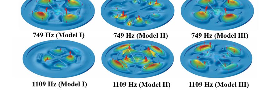
Polymers 2021, 13, 1146                                                                                                    3 of 18

                                    topology, from some points of view, coincides with the locally-resonant design concept.
                                    The combination of the delicate natural arrangement of web-nodes and thin-films may
                                    provide better insights for the MAMs with functionalities of noise reduction, which has
                                    not been investigated, but deserves a further exploration.
                                         In this research, we introduce the bionic configuration philosophy into the MAM de-
                                    sign. Aiming to reduce structural weight and broaden low-frequency attenuation band-
                                    width, two MAM models, inspired by the spider web topology, are proposed and fabri-
                                    cated by polymeric membrane and attached resonators. The coupling vibration mecha-
                                    nisms between the bio-inspired arrangement and the host polymeric film are systemati-
                                    cally investigated and compared with the traditional MAM configuration. The remarkable
                                    enlargements in the bandwidth of low-frequency sound attenuation, but with lighter
                                    weight design, are performed by both numerical and experimental verifications.

                                    2. Structural Design and Methods
                                    2.1. Spider Web-Inspired MAMs
                                         As shown in Figure 1, a typical spider web presents a structure with both radial and
                                    multi-layer circumferences. The spider silks distribute with an interval of intersecting
                                    nodes along both the circumferential and radial directions. Inspired by such classical dis-
                                    tribution of the spider web knots, two kinds of MAM models, Models I and II, are inves-
                                    tigated and compared in this research. Models I and II are designed based on the opti-
                                    mized bionic structure design. In addition, a reference model taken from the existing
                                    work, Model III, is selected for comparison [35].

                          Figure 1. Schematic diagram of the MAM designs inspired by the spider web topology.

                                         In all models, a polyimide (PI) film with a thickness of 0.2 mm is fixed by a host ring
                                    structure around the circumferential boundary. The host ring is made by the ethylene vi-
                                    nyl acetate copolymer (EVA). A central cross, also made by EVA is positioned on the
                                    membrane center to mimic the intersecting center of the spider web. Both the EVA ring
                                    and cross structure are fabricated by 3D printing. For Models I and II, two kinds of “knots”
                                    resonators, strip-type and cross-type, are attached along the radial directions to roughly
                                    describe the radial spider web shape. The knot-like vibrators attached to the PI membrane
                                    are arranged by arch to fit the radial/circumferential direction or both at the same time,
                                    leading to a better match with the spider web characteristics.
                                         Specifically for Model I, only strip-type resonators are attached along four radial cor-
                                    ners to fit the circumferential direction of a spider web structure. For Model II, both strip-
                                    type and cross-type resonators are alternatively arranged along eight radial corners to fit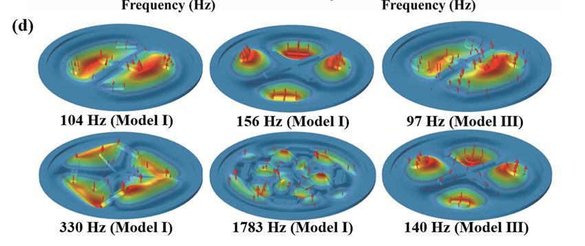
Polymers 2021, 13, 1146                                                                                          4 of 18

                          the radial and circumferential directions simultaneously. The circle formed by the plane
                          geometric center positions of the four “arms” is taken as the first circle of the spider web,
                          while the position of the “knots” corresponding to the frame is applied to mimic the sec-
                          ond circle of the spider web. For the existing reference Model III, the resonators are disc-
                          types located at the four same radial corners of Mode I. According to the existing reference
                          Model III, we determine the basic dimensions of the host membrane and ring structure. A
                          further improvement is conducted by changing the resonator shape and mass with refer-
                          ence to the spider web, while keeping the position unchanged, but ensuring the mass is
                          lighter than the reference model. Then, we conduct a frequency sweep and make slight
                          dimension adjustments to achieve the target working frequencies.
                                For the reference Model III, the EVA ring is 2 mm thick, with an outer diameter of
                          100 mm and a width of 5 mm; the EVA large cross structure is 2 mm thick and the four
                          carbon steel discs have a diameter of 1.8 mm. For Models I and II, the thickness and ma-
                          terial of all bio-inspired vibrators are the same as the reference model III. The gravity cen-
                          ters of the strip-type and cross-type metal resonators in Models I and II are also the same
                          as the disc-type metal resonators in Model III. Moreover, four small strip-type metal res-
                          onators in Model II are perpendicular to the four arms of EVA large cross structure, re-
                          spectively. For the models, the radius of the circle defined by the centers of the four disc-
                          type, strip-type or cross-type metal resonators is around 28 mm. The strip-type metal res-
                          onator and cross-type metal resonator have the same plane area of 52 mm2, while the plane
                          area of the small strip-type metal resonator in Model II is 28 mm2. The material parameters
                          in the numerical models are listed in Table 1, and the 3D graphics and dimensions of the
                          structure on the membrane for the three models are shown in Figure A1 (See Appendix
                          A). It should be mentioned that the total resonators’ weight in Model I is much lighter
                          than that in the reference model (Model III), which is only around a half; for Model II, it
                          is also lighter than that in Model III, around 80%.

                          Table 1. Material parameters in the membrane-type metamaterial models.

                                          Young's Modulus (Pa)              Density (kg/m3)         Poisson's Ratio
                            PI                 1.42 × 10⁹                        1100                    0.36
                           EVA                  1.7 × 10⁸                        2050                    0.45
                           Metal                 2 × 10¹¹                        7800                    0.33

                          2.2. Numerical Acoustic-Structure Models
                               A commercial FEA software, COMSOL Multiphysics (Stockholm, Sweden), is ap-
                          plied to establish the numerical models of the proposed MAMs, and the Acoustic-Struc-
                          ture Coupling module is utilized to analyze the STL characteristics. This module can de-
                          scribe the coupling of solid objects and three-dimensional acoustic fluid phenomena. As
                          shown in Figure 2a, the solid mechanics part is first affected by the sound pressure to
                          calculate the frequency response of the diaphragm, which then transmits it to the aeroa-
                          coustics domain at the other end, where an analysis is made. IS (incident surface) is the
                          sound incident surface, IPF (incident pressure field) denotes the incident sound field,
                          while TPF (transmitted pressure field) is the transmission sound field. PML (perfectly
                          matched layer) is used to completely absorb the transmitted sound at the boundary to
                          avoid boundary reflection. The air domain boundary (TPF, IPF) is set as the hard sound
                          field boundary. A unit IPF is applied on the IS. The boundary around the MAM is set as
                          a fixed constraint. The contact surface between MAM and TPF/IPF is set as the acoustic-
                          structure boundary. The STL properties are calculated by the transmittance under a sweep
                          frequency range, and the numerical model after meshing is shown in Figure 2b.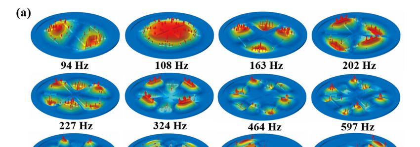
Polymers 2021, 13, 1146                                                                                                       5 of 18

                                 Figure 2. Numerical acoustic-structure models of the MAMs for (a) STL calculation, (b) finite ele-
                                 ment mesh.

                                 2.3. Experimental Setup
                                      Under the testing standard of ASTM E2611-09 [36], the sound isolation performance
                                 of the designed MAM models is experimentally investigated by using the acoustic imped-
                                 ance tube. The transmission matrix method is used to experimentally measure the trans-
                                 mission coefficients and the STL. The schematic diagram of experimental setup is illus-
                                 trated in Figure 3a. The snapshots of prototype and test samples are shown in Figure 3b.

      Figure 3. (a) Schematic diagram and (b) snapshots of the experimental setup for STL testing in acoustic impedance tube.
      Inset in (b): the fabricated samples for the three models.

                                      The four-microphone testing method with fixed positions was applied to measure
                                 the bio-inspired MAMs. The diameter of the acoustic impedance tube is 100 mm, and the
                                 measurement frequency range is from 80 Hz to 1600 Hz with a sampling interval of
                                 0.78125 Hz. A compensation constant is applied for the material adjustment. The installa-
                                 tion of the test piece was sealed with a rubber ring to reduce the influence of sound leak-
                                 age on the transmission loss. Due to the geometric asymmetry of the experimental speci-
                                 mens, the incidence and reflection coefficients are not the same on both sides. Therefore,
                                 the four microphones (A/B/E/F) (see Figure 3a) of the impedance tube farthest from the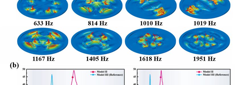
Polymers 2021, 13, 1146                                                                                          6 of 18

                          specimen are selected. During testing, the direct distance between the microphone and
                          the specimen should be far enough to ensure that the measured transfer function falls in
                          a plane wave region. The air temperature in the tube is 24°C; thus, the sound speed in the
                          tube (cs = 346 m/s) and the wavelength (λ) corresponding to each measurement frequency
                          (f) can be calculated.
                                The background noise in the testing environment was firstly measured and then sub-
                          tracted from the measured result. The loudspeaker was adjusted to ensure that the meas-
                          ured signal amplitudes at all measuring frequencies were at least 10 dB higher than the
                          background noise. Moreover, signal amplitudes with 60 dB lower than the maximum fre-
                          quency response were also filtered out to ensure that the captured signals are as smooth
                          as possible. Each measurement is repeated 10 times and then averaged to reduce the ran-
                          dom errors and improve the signal-to-noise ratio. The stability evaluation under different
                          repeated times is provided in Appendix B. The transfer function was also determined by
                          the four-microphone method, which was corrected in advance before the formal measure-
                          ment. The transfer functions were determined by the measurements from microphones A
                          to B, E and F without specimen in the tube, respectively. Then, the positions of the two
                          corresponding microphones were exchanged and the transfer functions were measured
                          again. All the measurement results were used to correct the mismatch.
                                The STL was calculated based on the twice-measurement approach. During the first
                          measurement, a thick sound-absorbing cotton was inserted into the end of the tube, which
                          was removed during the second measurement. The transfer matrix can reflect the inherent
                          physical properties of the structure and will not change with the end conditions of the
                          pipeline. The corresponding measurement results were represented by subscripts a and b,
                          respectively. The sound pressure p and particle velocity u on both sides of the specimen
                          has the relationship shown in Equation (1) and Equation (2):

                                                                      =                                              (1)

                                                                      =                                              (2)

                          where [ ] is the transfer matrix and = 0 and = denote the location coordinates of
                          the sample’s two ends. The four intermediate parameters (IP) of the four microphones
                          (A/B/E/F) can be calculated by using Equations (3)–(6):
                                                                                                  (   )
                                                                 ,            −           ,
                                                           =                                                         (3)
                                                                          2

                                                                          (       )
                                                                  ,                   −       ,
                                                           =                                                         (4)
                                                                          2

                                                                          (       )
                                                                  ,                   −       ,
                                                           =                                                         (5)
                                                                          2

                                                                                                  (   )
                                                                 ,            −           ,
                                                           =                                                         (6)
                                                                          2

                          where       is the distance between microphone A and B,         is the distance between micro-
                          phone E and F,        and      are the distances between the reference surface (the front and
                          back surfaces of the test piece) and microphone 2 or microphone 3, respectively, 2 and 3
                          refers to B and E and        ,    = 1 is the transfer function from the reference microphone
                          to the i-th microphone.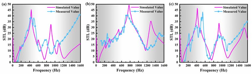
Polymers 2021, 13, 1146                                                                                      7 of 18

                               In the STL test, the reference microphone is microphone A. Thus, for the reference
                          microphone,       ,    = 1. The sound pressure p and particle velocity u on both sides of
                          the specimen can be expressed by Equation (7) and Equation (8):

                                                                        = +
                                                                                                                (7)
                                                                      = ( − )/

                                                                 =              +
                                                                                                                (8)
                                                                =(          −            )/

                          where and are the density and sound speed, respectively. According to the above
                          equations, the transfer matrix can be obtained by using the twice-measurement method
                          as:
                                                                 −                  0b    −
                                                                 −                        −
                                                      =          −                        −                     (9)
                                                                 −                        −
                          Based on the transfer matrix, the transmission coefficient can be calculated as:

                                                                            2
                                                            =                                                  (10)
                                                                  +     /       +         +

                          The relevant STL can be further written as:

                                                                                    1
                                                                  STL=20                                       (11)

                          3. Results and Discussion
                          3.1. STL and Anti-Resonance Modes
                                Numerically calculated and experimentally measured STL properties of the three
                          MAM models are depicted and compared in Figure 4a–c, respectively. In general, very
                          good agreements are obtained between numerical and experimental results for all the ref-
                          erence and bio-inspired models, although certain derivations in both STL peaks and fre-
                          quency ranges are exhibited. Overall, the experimentally measured STL peaks are slightly
                          less than the numerical results, which is mainly induced by the manufacturing accuracy
                          and ignoring the damping effect in numerical models. In addition, a better agreement be-
                          tween numerical and experimental STL bandwidths is exhibited in the low-frequency
                          range than the high frequency range (above 1200 Hz). It can be understood because the
                          fixed boundary condition of the ring, the bonding status between the resonators and the
                          membrane during experimental testing, which normally have more of an effect on the
                          high-frequency performance, cannot be guaranteed to be ideal.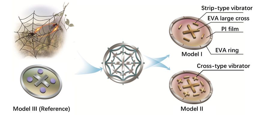
Polymers 2021, 13, 1146                                                                                             8 of 18

      Figure 4. Comparison between numerically simulated and experimentally measured STL properties: (a) Model I, (b)
      Model II, (c) Model III.

                                    To illustrate the sound isolation mechanisms, several mode shapes of the reference
                               MAM model at representative frequencies are illustrated, as shown in Figure 5a. It is il-
                               lustrated that within the selected low-frequency range, the reference model can generate
                               a series of continuous, multi-state anti-resonance modes by virtue of the symmetrically
                               distributed multi-resonators, which can keep trapping the vibration energy and maintain
                               the dynamic balances within a relatively broad bandwidth, leading to a broadband, low-
                               frequency sound-isolation performance. Such multi-set anti-resonance behaviors of the
                               reference model agree with the observation in the reported research [35]. In that work, it
                               was also demonstrated that the STL bandwidth and attenuation peaks of the reference
                               model are greatly improvement compared to the other traditional MAM structures. How-
                               ever, much effort still needs to be made to achieve a better STL performance within a
                               wider low-frequency bandwidth while using a lighter MAM design. This pivotal devel-
                               opment aspect is the most concern in our research.

                               3.2. Bandwidth Widening in Lighter Bio-Inspired Designs
                                    The comparisons of sound-isolation performance between the bio-inspired and ref-
                               erence MAM models are systematically investigated and discussed in this section. Several
                               typical indexes are defined to quantitatively evaluate the sound-isolation performance.
                               The frequency range between the first and second troughs in the STL spectrum is defined
                               as the 1st STL bandwidth, , and the corresponding boundary trough frequencies are
                               defined as     and    . The normalized bandwidth for        is defined as   =        . Simi-
                               larly, the frequency range between the second and third troughs was defined as the 2nd
                               STL bandwidth, . Furthermore, in a certain frequency range of 0–1600 Hz, we define a
                               total bandwidth as to evaluate the overall performance, in which the corresponding
                               STL is greater than 10 dB.
                                     The comparison between the STL profiles of the bio-inspired Model I and the refer-
                               ence model (Model III) is illustrated in Figure 5c. The corresponding typical indexes are
                               listed in Table 2. Compared with Model III, Model I has almost the same STL curve for
                               the first two STL bandwidths. The relevant normalized bandwidth          and the total band-
                               width for the two models are also very similar (see Table 2). However, it is worth men-
                               tioning that the total resonators’ weight of the bio-inspired Model I is only 52.78% of that
                               in the reference model. Excitingly, it is demonstrated that by using only a half of the
                               weight, a nearly equal sound-isolation performance can be achieved by using the spider
                               web-inspired design, which is a significant development in weight reduction.
Polymers 2021, 13, 1146                                                                                               9 of 18

                          Figure 5. (a) Mode shapes of Model III (reference) at representative frequencies. (b) Mode shapes
                          of Model I at representative frequencies. (c) Comparison between the STL profiles of the bio-in-
                          spired Model I and Model III (reference). (d) Mode shapes of Model I and the reference Model III
                          at several typical frequencies.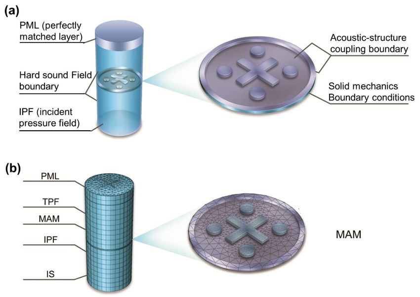
Polymers 2021, 13, 1146                                                                                                10 of 18

                                        Several mode shapes of Model I at the typical frequencies are visualized in Figure 5b
                                   to explain the underlying physics. Compared with the reference model (see Figure 5d),
                                   the bio-inspired Model I has similar dipole and quadrupole modes corresponding to 104
                                   Hz and 156 Hz. Moreover, there are also some new kinds of anti-resonance modes gener-
                                   ated in Mode I, corresponding to 330 Hz and 1783 Hz (Figure 5d), due to the circumfer-
                                   ential distribution of the strip-type resonators. Among them, the mode shape correspond-
                                   ing to 330 Hz is caused by one end of two adjacent large strip-shape vibrators, while the
                                   mode corresponding to 1783 Hz reflects the further division of the original mode by the
                                   small cross-type resonator. Such new generated modes, not shown in the reference model,
                                   maintain the broad low-frequency bandwidths even though the total resonators’ weight
                                   is reduced by half. Additionally, these multi-set responses make the STL curves of some
                                   frequency bands smoother (Figure 5c), which ensures that the bio-inspired Model I has a
                                   lighter vibrator while it processes almost the same STL curve as the reference model at
                                   low frequencies.

                       Table 2. Comparison of STL properties between spider web models and the reference model.

                                                                                                     Bandwidth of
      Vibrator area                   STL Peak                                                         STL (Hz)
Model               Vibrator mass (g)
         (mm2)                          (dB) (Hz) (Hz) (Hz)             (Hz) (Hz) (Hz)                 (>10 dB)
                                                                                           Within 1600 Hz( ) Within 3000 Hz
    I       4 × 52              2.92          45.4    55 750 695 12.64 750 1035 285 0.38         1010             2250
   II       4 × 80              4.49          49.2    50 1170 1120 22.4 1170 1825 655 0.56       1465             2360
  III      4 × 98.52            5.52          46.5    55 750 695 12.64 750 1130 380 0.51         1160             2340

                                         Correspondingly, the vibration mode shapes and STL properties for the bi-inspired
                                   Model II are illustrated in Figure 6a,b, respectively. Compared with the reference model
                                   (Model III), the STL bandwidth and peak value of Model II have been improved in the
                                   low frequency range (see Figure 6b). Model II has a STL peak of nearly 50 dB with a band-
                                   width of 1120 Hz from 50 Hz to 1170 Hz, which is 61% wider than the maximum single-
                                   peak bandwidth (695 Hz) of the reference model. Remarkably, the normalized bandwidth
                                       for Model II has a nearly 80% broadening than the reference model. Moreover, the total
                                   bandwidth, greater than 10 dB within 1600 Hz, is 1465 Hz for Model II, which is 26% wider
                                   than that of the reference model (1160 Hz). The remarkable total bandwidth accounts
                                   more than 91% of the sampling interval of 0–1600 Hz. Furthermore, the STL peak of Model
                                   II increases to 49.24dB at 775 Hz, which is also higher than the reference model (46.5dB).
                                   However, the total vibrator mass of Model II is still 19% lighter than that of the reference
                                   model.
                                         Several mode shapes of Model II at the typical frequencies are visualized in Figure
                                   6a to explain the underlying physics. The representative mode shapes are extracted and
                                   compared with the other modes in Figure 6c. It can be seen that the STL curves of the
                                   reference model and Model I are in the trough at the frequencies of 749 Hz and 1109 Hz,
                                   which shows similar modes and are much different from the modes of Model II at the
                                   corresponding frequencies. For the mode shapes of Model II, the four small strip-type
                                   vibrators and four cross-type vibrators merge into a shape similar to a spider web, which
                                   further divide the resonance modes of Model I, forming more local anti-resonance modes.
                                   The peaks of the STL curves generated by the new local anti-resonance modes effectively
                                   suppress the generation of troughs at similar frequencies in Model I. At the same time,
                                   more STL peaks at similar frequencies are generated by the new, continuous local anti-
                                   resonance modes. More remarkably, these adjacent peaks merge together with each other,
                                   leading to a large continuous peak in a significant wide frequency band, thus broadening
                                   the STL bandwidth and increasing the STL peak value. The bio-inspired designs allow us
                                   to demonstrate a great enhancement in sound suppression performance at a low-fre-
                                   quency broadband with a lighter weight.
Polymers 2021, 13, 1146 11 of 18
Figure 6. (a) Mode shapes of Model II at representative frequencies. (b) Comparison between the
STL profiles of the bio-inspired Model II and the reference model. (c) Mode shapes of Model I,
Model II and the reference Model III at several typical frequencies.
The comprehensive performances of the two bio-inspired models and the reference
model (Model III) are further compared in the form of radar chart, as shown in Figure 7.
Four typical parameters are selected to quantitatively evaluate the sound attenuation per-
formance, as well as the structural weight. and describe the bandwidth of the low-
frequency sound attenuation performance. The peak value indicates the maximum STL
ability, while the reciprocal of vibrator mass indicates the structural lightweight level. The
reciprocal form is taken to describe the performance level uniformly. The cover area of the
overall profile indicates the performance level of the sound attenuation, where thePolymers 2021, 13, 1146 12 of 18
structural weight is also considered. It is evident that the higher the above parameters are,
the better the comprehensive performance of the model is. It is observed that the proposed
Model II covers the largest property area, which has a remarkable enhancement in the
overall performance than both the reference model and Model I (Figure 7a). The sound
reduction bandwidth and maximum STL performance of Model I are almost the same as
that of the reference model, but its lightweight level shows a dramatic improvement (Fig-
ure 7b), which is highly desired for practical application. Model II is superior to the refer-
ence model in all dimensions (see Figure 7c). In particular, the normalized bandwidth
in Model II is almost 180% of that in the reference model, which is a significant enhance-
ment. These comparisons unambiguously verify the outstanding sound attenuation per-
formance by using the bio-inspired MAM design strategies.
Figure 7. (a) Comparison of the overall performance between the two bio-inspired modes and the reference model. (b)
Comparison of the overall performance between Model I and reference Model III, (c) Model II and reference Model III.
3.3. Effects of the Shape Design and Membrane Parameters
The effects of the shape design and membrane parameters on the sound attenuation
performance are further discussed. It is shown in Figure 8a that for the strip-type and
cross-type resonators with the same mass and central positions, the overall trends of their
STL profiles are basically same, but the peak frequencies of the cross-type design have a
slight back-shift; additionally, the attenuation bandwidth has a minor enlargement. Fur-
thermore, the influence of each design part on the bandwidth broadening in Model II is
discussed. It can be observed in Figure 8b that if all stripe-type resonators are removed
from Model II (only cross-type left), the main attenuation bands are around 200–700 Hz
and 800–1100 Hz. If all cross-type resonators are removed from Model II, the attenuation
bands are mainly around 200–500 Hz, 700–900 Hz and 1000–1200 Hz. The attenuation
bands induced by the two kinds of resonators are alternately generated. However, there
is no merging effect on bandwidth if only one type is left. Remarkably, when the two types
are arranged together (Model II), these adjacent, alternant attenuation bands are merged
together by the coupling effect, leading to a broadening band in an ultra-wide frequency
range. It is demonstrated that the significant bandwidth broadening in Model II is induced
by the coupling between the two types of resonators.
To make the cobweb-inspired structure more intuitive, we also constructed a curved
Model II and compared its performance with the straight one, as illustrated in Figure 8c.Polymers 2021, 13, 1146 13 of 18
In the curved model, all the straight bars along the circumferential direction are designed
as arcs, but with the same mass as the straight one. Excitingly, the curved design presents
a wider attenuation bandwidth in low-frequency range than the straight one under the
same mass and positions. It is further demonstrated that the resonator shape and arrange-
ment play a significant role in the sound attenuation bandwidth.
Figure 8. Comparison between the STL profiles of different resonator-shape designs: (a) strip-type and cross-type designs,
(b) Model II without (w/o) stripe-type or cross-type, (c) straight and curved Model II designs.
Furthermore, the bio-inspired Model II is employed for the sensitivity analysis of the
polymeric membrane material. Three material parameters, Young’s modulus, density and
Poisson’s ratio, are applied for the discussion. The parts containing EVA material in
Model II include the central large cross and the frame. The frame mainly plays a fixed role
and has little effect if the structural parameters are stable. Therefore, changing the material
parameters mainly affects the performance of the EVA large cross. A series of EVA
Young's moduli ranging from 40% to 160% of the original value are selected for discus-
sion.
As shown in Figure 9a, when the Young's modulus of the EVA material is changed
from 0.68 × 10⁸ Pa to 2.72 × 10⁸ Pa, the 1st STL bandwidth gradually increased from 530
Hz to 795 Hz. In addition, the first low-frequency STL peak does not change too much,
and the position of the second low-frequency STL peak gradually moves backward while
the value gradually decreases. Therefore, in the range of Young's modulus from 0.68 × 10⁸
Pa to 2.72 × 10⁸ Pa, the model with the maximum Young's modulus of the EVA material
presents the STL curve with the best performance.
For the analysis of the influence of density on Model II, the density of the EVA mate-
rial used in this study is 2050 kg/m3, and 40%–160% of the original EVA density was se-
lected for calculation. As shown in Figure 9b, when the EVA density is gradually changed
from 820 kg/m3 to 3280 kg/m3, the bandwidth of the 1st bandwidth gradually narrows
varying from 800 Hz to 605 Hz, the first low-frequency STL peak value gradually becomes
higher and the position of the second low-frequency STL peak gradually moves forward
while its value gradually increases. This result is opposite to the result corresponding to
the change of Young's modulus. It is worth noting that when the density of EVA material
is 820 kg/m3 or 1230 kg/m3, the first low-frequency STL peak separates. Therefore, even if
the bandwidth of the first low-frequency STL peak of the low-density material is wide, it
is necessary to comprehensively consider whether it is separated, because the separation
would cause the first low-frequency STL peak to be far smaller than the expected one. In
contrast, choosing a density of 1640 kg/m3 or 2050 kg/m3 is acceptable.
For the analysis of the influence of Poisson's ratio on Model II, the Poisson's ratio of
the EVA material used in this study is 0.45, and 40%–100% of the original Poisson's ratioPolymers 2021, 13, 1146 14 of 18
of the EVA material was selected for calculation. As shown in Figure 9c, when the Pois-
son's ratio of EVA material in Model II is gradually increased from 0.18 to 0.45, the band-
width of the first low-frequency STL peak gradually widens, but the degree of change is
much smaller than the change caused by changing the same percentage of Young's mod-
ulus and density. In addition, the change of the second low-frequency STL peak band-
width is also very slight, indicating that the Poisson’s ratio of the membrane material has
little effect on the performance of its STL curve.
Figure 9. Analysis of the influence of material properties on the STL curves: (a) Young's Modulus, (b) density and (c)
Poisson's ratio.
4. Conclusions
In this paper, we propose two kinds of spider web-inspired membrane-type met-
amaterials for broadband low-frequency sound isolation. The bionic philosophy is com-
bined with the design concept of acoustic metamaterials to build compact meta-structures
with both prominent sound attenuation and lightweight performance. The proposed de-
signs are fabricated by a host polymeric membrane and attached resonators. Based on the
numerical and experimental investigations on the sound isolation behaviors, the follow-
ing conclusions can be obtained.
1. By using the proposed bio-inspired MAM models, significant sound attenuation
within a broadband low-frequency range is achieved. It is verified that the prominent
attenuation performance is induced by the multi-state anti-resonance modes of the
symmetrically distributed multi-resonators. Such unremitting anti-resonance behav-
iors can maintain the dynamic balances within a wide bandwidth by trapping the
vibration energy.
2. The experimentally measured STL properties of the bio-inspired MAM structures are
discussed and compared in depth. Remarkably, compared with a reference MAM
model, outstanding enhancements in both attenuation bandwidth and weight-reduc-
tion performance are illustrated in the spider web-inspired designs.
3. Specifically, the bio-inspired Model I can significantly reduce the structure weight by
nearly half (47%), but still maintain a same sound attenuation property as the refer-
ence model. The bio-inspired Model II can greatly enhance the comprehensive sound
attenuation while keeping a lighter weight design (19% less than the reference
model). The continuous attenuation bandwidth in the proposed Model II has a 61%
increase compared to the reference model, while the normalized bandwidth has a
significant ~80% broadening.
4. The arrangement of the spider web structure can enhance the coupling interaction
between the multi-resonators and host film along the circumferential and radial di-
rections. Therefore, more adjacent, multi-state anti-resonance modes are generated
in the low-frequency range to suppress the discontinuity, leading to a broadening
attenuation bandwidth.Polymers 2021, 13, 1146 15 of 18
The proposed bio-inspired MAM strategies allow us to demonstrate dramatic sound-
suppression performance in both high functionality and lightweight design, which pave
the way for feasible and compact sound isolation devices.
Author Contributions: Conceptualization, H.H. and B.L.; Data curation, E.C.; Funding acquisition,
H.H. and B.L.; Investigation, H.H., E.C. and S.A.; Methodology, H.H., E.C. and B.L.; Project admin-
istration, M.Z.; Resources, M.Z. and B.L.; Supervision, B.L.; Validation, H.H. and E.C.; Visualization,
H.H. and S.A.; Writing—original draft, H.H. and E.C.; Writing—review and editing, B.L. All authors
have read and agreed to the published version of the manuscript.
Funding: This research work was supported by the National Natural Science Foundation of China
(No. 11902262), the Innovation Capability Support Plan of Shaanxi Province (No. 2020KJXX-067),
the Key Research and Development Plan of Shaanxi Province (KQTD20140630154026047) and the
Deanship of Scientific Research at King Khalid University (grant no. R.G.P.2/127/42).
Institutional Review Board Statement: Not applicable.
Informed Consent Statement: Not applicable.
Data Availability Statement: The data presented in this study are available on request from the
corresponding author.
Conflicts of Interest: The authors declare no conflict of interest.
Appendix A
The 3D graphics and dimensions of the structure on the membrane for the three mod-
els in this paper are shown in Figure A1. The material of EVA cross and EVA frames parts
is EVA, prepared by 3D printing; the material of disc-type metal vibrator, small cross-type
metal vibrator, large strip-type metal vibrator and small strip-type metal vibrator is 45
steel, prepared by machining. These vibrators were assembled into all models by bonding
with PI film and EVA frames.
Figure A1. 3D graphics and dimensions of the EVA cross (a), disc-type metal vibrator (b), small
cross-type metal vibrator (c), large strip-type metal vibrator (d) and small strip-type metal vibrator
(e). The length unit is millimeter.
Appendix B
For each model, four samples are fabricated to evaluate the manufacturing and meas-
urement accuracy. The relative errors of STL characteristics ( and ) between the four
tests are listed in Table A1. The measured average values with error bars for the threePolymers 2021, 13, 1146 16 of 18
membrane-type metamaterial models are shown in Figure A2. It is observed that the max-
imum relative error range is −7.1%–5.74%, which is an acceptable range for the manufac-
turing and measurement accuracy.
Table A1. The relative errors between four sample tests.
Test 1 Test 2 Test 3 Test 4
Model STL Relative error (%)
(Hz) (Hz) (Hz) (Hz)
505 529 523 471 −7.10~4.34
I
1291 1195 1321 1202 −4.57~5.49
1049 1062 1083 1006 −4.19~3.14
II
1485 1480 1442 1467 −1.80~1.12
559 507 576 537 −6.93~5.74
III
1240 1187 1221 1179 −2.30~5.49
Figure A2. The average value of and by measuring four samples for each model.
The comparison of the measured spectrums under different repeated times is con-
ducted to check the stability. Figure A3 illustrates the spectrum signals captured from
microphone A after 1, 5, 10 and 20 repeated times. It is observed that the spectrum signal
has become quite stable after being repeated 10 times. Therefore, the repeated time is se-
lected as 10 during the experimental measurement.
Figure A3. Spectrum signals captured from microphone A after various repeated times.Polymers 2021, 13, 1146 17 of 18
References
1. Poletti, C.; Buchwald, B.; Lewin, P.; Harris, C.M. Handbook of Noise Control. Columbia Law Rev. 1958, 58, 580,
doi:10.2307/1119589.
2. Mei, J.; Ma, G.; Yang, M.; Yang, Z.Y.; Wen, W.; Sheng, P. Dark acoustic metamaterials as super absorbers for low-frequency
sound. Nat. Commun. 2012, 3, 756, doi:10.1038/ncomms1758.
3. Liao, Y.; Chen, Y.; Huang, G.; Zhou, X. Broadband low-frequency sound isolation by lightweight adaptive metamaterials. J.
Appl. Phys. 2018, 123, 091705, doi:10.1063/1.5011251.
4. Ma, F.; Wu, J.H.; Huang, M.; Zhang, W.; Zhang, S. A purely flexible lightweight membrane-type acoustic metamaterial. J. Phys.
D: Appl. Phys. 2015, 48, 175105, doi:10.1088/0022-3727/48/17/175105.
5. Liu, Z.; Zhang, X.; Mao, Y.; Zhu, Y.Y.; Yang, Z.; Chan, C.T.; Sheng, P. Locally Resonant Sonic Materials. Sci. 2000, 289, 1734–
1736, doi:10.1126/science.289.5485.1734.
6. Cummer, S.A.; Christensen, J.; Alù, A. Controlling sound with acoustic metamaterials. Nat. Rev. Mater. 2016, 1, 16001,
doi:10.1038/natrevmats.2016.1.
7. Ma, G.; Sheng, P. Acoustic metamaterials: From local resonances to broad horizons. Sci. Adv. 2016, 2, e1501595–1501595,
doi:10.1126/sciadv.1501595.
8. Fang, N.; Xi, D.; Xu, J.; Ambati, M.; Srituravanich, W.; Sun, C.; Zhang, X. Ultrasonic metamaterials with negative modulus. Nat.
Mater. 2006, 5, 452–456, doi:10.1038/nmat1644.
9. Li, B.; Li, Z.; Christensen, J.; Tan, K.T. Dual Dirac cones in elastic Lieb-like lattice metamaterials. Appl. Phys. Lett. 2019, 114,
081906, doi:10.1063/1.5085782.
10. Gao, S.; Liu, W.; Zhang, L.; Gain, A.K. A New Polymer-Based Mechanical Metamaterial with Tailorable Large Negative Pois-
son′s Ratios. Polym. 2020, 12, 1492, doi:10.3390/polym12071492.
11. Zhang, W.; Zhao, S.; Sun, R.; Scarpa, F.; Wang, J. In-Plane Mechanical Behavior of a New Star-Re-Entrant Hierarchical Met-
amaterial. Polym. 2019, 11, 1132, doi:10.3390/polym11071132.
12. Ding, Y.; Liu, Z.; Qiu, C.; Shi, J. Metamaterial with Simultaneously Negative Bulk Modulus and Mass Density. Phys. Rev. Lett.
2007, 99, 093904, doi:10.1103/physrevlett.99.093904.
13. Zhu, R.; Liu, X.N.; Hu, G.K.; Sun, C.T.; Huang, G.L. Negative refraction of elastic waves at the deep-subwavelength scale in a
single-phase metamaterial. Nat. Commun. 2014, 5, 5510, doi:10.1038/ncomms6510.
14. Li, B.; Tan, K.T.; Christensen, J. Tailoring the thermal conductivity in nanophononic metamaterials. Phys. Rev. B 2017, 95, 144305,
doi:10.1103/physrevb.95.144305.
15. Chen, Y.; Qian, F.; Scarpa, F.; Zuo, L.; Zhuang, X. Harnessing multi-layered soil to design seismic metamaterials with ultralow
frequency band gaps. Mater. Des. 2019, 175, 107813, doi:10.1016/j.matdes.2019.107813.
16. Craster, R. V.; Guenneau, S., Acoustic metamaterials: Negative refraction, imaging, lensing and cloaking. Springer Science &
Business Media: 2012; Vol. 166.
17. Nassar, H.; Yousefzadeh, B.; Fleury, R.; Ruzzene, M.; Alù, A.; Daraio, C.; Norris, A.N.; Huang, G.; Haberman, M.R. Nonreci-
procity in acoustic and elastic materials. Nat. Rev. Mater. 2020, 5, 667–685, doi:10.1038/s41578-020-0206-0.
18. Hirsekorn, M. Small-size sonic crystals with strong attenuation bands in the audible frequency range. Appl. Phys. Lett. 2004, 84,
3364–3366, doi:10.1063/1.1723688.
19. Li, B.; Zhang, C.; Peng, F.; Wang, W.; Vogt, B.D.; Tan, K.T. 4D printed shape memory metamaterial for vibration bandgap
switching and active elastic-wave guiding. J. Mater. Chem. C 2021, 9, 1164–1173, doi:10.1039/d0tc04999a.
20. Oudich, M.; Senesi, M.; Assouar, M.B.; Ruzenne, M.; Sun, J.-H.; Vincent, B.; Hou, Z.; Wu, T.-T. Experimental evidence of locally
resonant sonic band gap in two-dimensional phononic stubbed plates. Phys. Rev. B 2011, 84, 165136,
doi:10.1103/physrevb.84.165136.
21. Yang, Z.; Mei, J.; Yang, M.; Chan, N.H.; Sheng, P. Membrane-Type Acoustic Metamaterial with Negative Dynamic Mass. Phys.
Rev. Lett. 2008, 101, 204301, doi:10.1103/physrevlett.101.204301.
22. Ang, L.Y.L.; Koh, Y.K.; Lee, H.P. Broadband sound transmission loss of a large-scale membrane-type acoustic metamaterial for
low-frequency noise control. Appl. Phys. Lett. 2017, 111, 041903, doi:10.1063/1.4995405.
23. Naify, C.J.; Chang, C.-M.; McKnight, G.P.; Nutt, S.R. Transmission loss and dynamic response of membrane-type locally reso-
nant acoustic metamaterials. J. Appl. Phys. 2010, 108, 114905, doi:10.1063/1.3514082.
24. Naify, C.J.; Chang, C.-M.; McKnight, G.P.; Scheulen, F.; Nutt, S.R. Membrane-type metamaterials: Transmission loss of multi-
celled arrays. J. Appl. Phys. 2011, 109, 104902, doi:10.1063/1.3583656.
25. Sui, N.; Yan, X.; Huang, T.-Y.; Xu, J.; Yuan, F.G.; Jing, Y., A lightweight yet sound-proof honeycomb acoustic metamaterial.
Applied Physics Letters 2015, 106, (17), 216101.
26. Wang, X.; Zhao, H.; Luo, X.; Huang, Z. Membrane-constrained acoustic metamaterials for low frequency sound insulation. Appl.
Phys. Lett. 2016, 108, 041905, doi:10.1063/1.4940717.
27. Chen, Y.; Huang, G.; Zhou, X.; Hu, G.; Sun, C.-T., Analytical coupled vibroacoustic modeling of membrane-type acoustic met-
amaterials: Membrane model. J. Acoust. Soc. Am. 2014, 136, (3), 969–979.
28. Naify, C.J.; Chang, C.-M.; McKnight, G.; Nutt, S.R. Transmission loss of membrane-type acoustic metamaterials with coaxial
ring masses. J. Appl. Phys. 2011, 110, 124903, doi:10.1063/1.3665213.
29. Knudson, D. V., Fundamentals of Biomechanics. Springer US, NY, USA, 2007, 2, 337, Available online:
https://www.springer.com/gp/book/9780387493114Polymers 2021, 13, 1146 18 of 18
30. Huston, R.L. Principles of Biomechanics; Apple Academic Press, NJ, USA, 2008, 1, 442, Available online: https://www.taylorfran-
cis.com/books/mono/10.1201/9781420018400/principles-biomechanics-ronald-huston
31. Hu, J.; Yu, T.; Yin, S.; Xu, J. Low-speed impact mitigation of recoverable DNA-inspired double helical metamaterials. Int. J.
Mech. Sci. 2019, 161-162, 105050, doi:10.1016/j.ijmecsci.2019.105050.
32. Sepehri, S.; Jafari, H.; Mashhadi, M.M.; Yazdi, M.R.H.; Fakhrabadi, M.M.S. Study of tunable locally resonant metamaterials:
Effects of spider-web and snowflake hierarchies. Int. J. Solids Struct. 2020, 204-205, 81–95, doi:10.1016/j.ijsolstr.2020.08.014.
33. Ma, F.; Wu, J.H.; Huang, M.; Fu, G.; Bai, C. Cochlear bionic acoustic metamaterials. Appl. Phys. Lett. 2014, 105, 213702,
doi:10.1063/1.4902869.
34. O Krushynska, A.; Bosia, F.; Miniaci, M.; Pugno, N.M. Spider web-structured labyrinthine acoustic metamaterials for low-fre-
quency sound control. New J. Phys. 2017, 19, 105001, doi:10.1088/1367-2630/aa83f3.
35. Zhou, G.; Wu, J.H.; Lu, K.; Tian, X.; Huang, W.; Zhu, K. Broadband low-frequency membrane-type acoustic metamaterials with
multi-state anti-resonances. Appl. Acoust. 2020, 159, 107078, doi:10.1016/j.apacoust.2019.107078.
36. ASTM E2611-09, Standard Test Method for Measurement of Normal Incidence Sound Transmission of Acoustical Materials
Based on the Transfer Matrix Method, ASTM International, West Conshohocken, PA, 2009. Available online:
https://www.astm.org/DATABASE.CART/HISTORICAL/E2611-09.htmYou can also read