Temporally Dense Ray Tracing - Nvidia
←
→
Page content transcription
If your browser does not render page correctly, please read the page content below
High-Performance Graphics (2019)                                                                                                               Short Paper
T. Foley and M. Steinberger (Editors)

                                                   Temporally Dense Ray Tracing

                                                 P. Andersson, J. Nilsson, M. Salvi, J. Spjut, and T. Akenine-Möller

                                                                              NVIDIA

         Abstract
         We present a technique for real-time ray tracing with the goal of reaching 240 frames per second or more. The core idea is to
         trade spatial resolution for faster temporal updates in such a way that the display and human visual system aid in integrating
         high-quality images. We use a combination of frameless and interleaved rendering concepts together with ideas from temporal
         antialiasing algorithms and novel building blocks—the major one being adaptive selection of pixel orderings within tiles, which
         reduces spatiotemporal aliasing significantly. The image quality is verified with a user study. Our work can be used for esports
         or any kind of rendering where higher frame rates are needed.
         Categories and Subject Descriptors (according to ACM CCS): I.3.7 [Computer Graphics]: Three-Dimensional Graphics and
         Realism—Ray Tracing

1. Introduction
Ray tracing has become the dominant visibility algorithm in film
and is growing in use for real-time applications thanks to the in-
troduction of the Microsoft DXR and Vulkan ray tracing APIs, and
NVIDIA RTX with GPU-hardware acceleration. While ray tracing                               Static          60 Hz            120 Hz           240 Hz
is becoming more accessible to real-time applications, more perfor-
mance is needed, particularly to hit the high refresh rates desired for              Figure 1: Static edge as antialiased over time with a jittered single
performance-critical applications. One such application is esports,                  sample per pixel. Photographs taken with 16.67 ms exposure time.
or competitive video games, which pit highly skilled profession-
als against each other and require the athletes to compete both in                   tialiasing (TAA) [Kar14] uses subpixel offsets and accumulation
response time and strategy. In these competitive scenarios, every                    over many frames and has been widely adopted in video games.
bit of advantage has the potential to determine which team wins                      TAA uses a variety of heuristics [PSK∗ 16], often tuned per applica-
or loses. The latency reduction provided by higher refresh rate dis-                 tion, to reduce the blurring, ghosting, and other artifacts commonly
plays (e.g., 16.7 ms at 60 Hz becomes 4.2 ms at 240 Hz) has been                     seen. Checkerboard rendering is another related method where 50%
shown to provide a corresponding competitive advantage in certain                    of the pixels are rendered each frame, and reprojection and averag-
esports-related tasks [KSM∗ 19].                                                     ing are used to produce the final frame [EM16].
   Given these potential advantages of higher frame rates and                           Our work builds on all the methods mentioned above. In addi-
emerging availability of high performance real-time ray tracing,                     tion, we adapt the algorithms to ray tracing at 240 Hz and present
it is natural to want use ray tracing to spread samples across                       a fundamental insight about how the sampling enumeration inside
time and enable a higher frequency of final frames, without in-                      tiles can reduce edge aliasing substantially if done well and in the
creasing the total number of samples. Frameless rendering is a                       right order. Our results include an increase in performance by a
technique where each ray or sample are given their own unique                        factor of approximately 3.5× with increased quality, compared to
time [BFMZ94, DWWL05]. While frameless rendering is good at                          TAA, and with the possibility to meet the 240 FPS goal, instead of
providing continuous updates of the world simulation, it requires                    running at 60 FPS, or slightly above.
running the world simulation for each sample taken, which in prac-
tice is a high cost. Therefore, a more moderate solution is to use
                                                                                     2. The Visual Power of 240 Hz
an approach like interleaved sampling [KH01] to cover the spa-
tial sampling desired over some number of frames, each of which                      It is challenging to convey what 240 Hz displays offer in terms
has samples located at pseudo-random positions. These samples                        of advantages for rendering via still pictures or using 60 frames
should then be combined using accumulation buffering [HA90] to                       per second (FPS) videos. We present two exceptions. Figure 1 at-
produce final frames. Spatiotemporal upsampling of only shading,                     tempts to illustrate the integration effect in the human visual sys-
while still using full resolution visibility and material information,               tem. Four images, each rendered with one sample per pixel (SPP)
can also be used to reduce shading cost [HEMS10]. Temporal an-                       from the standard 4× MSAA pattern, are shown after each other

 c 2019 The Author(s)
Eurographics Proceedings c 2019 The Eurographics Association.
P. Andersson et al. / Temporally Dense Ray Tracing
motion vectors
1 1 1 1
1 1 1 1 static dynamic
ray traced buffers moving full frame output
0 1 0 1 0 1 0 1
new window copy 0 1 0 1 0 1 0 1
2 03 12 03 12 03 12 03 1
average 2 3 2 3 2 3 2 3
0 1 0 1 0 1 0 1 moving
0 21 30021130021130021130 1 reproject
0 1 0 1 0 1 0 1
2 3 2 3 2 3 2 3 old window
2 03 12203312203312203312 3 & clamp
2 3 2 3 2 3 2 3
2 03 12 03 12 03 12 03 1 average
2 03 12 03 12 03 12 03 1
2 3 2 3 2 3 2 3
previous full frame
0 1 0 1 0 1 0 1
2 3 2 3 2 3 2 3
0 1 0 1 0 1 0 1
2 3 2 3 2 3 2 3
Figure 3: Our frame generation pipeline. We first render a subframe of lower resolution than the final output, while simultaneously retrieving
motion vectors for the corresponding pixels. This subframe together with the previously rendered subframes are then used to composite the
final frame. For each pixel in the final frame, we determine if its content is static or dynamic, and whether or not it corresponds to one of
the pixels that were just ray traced (new/old). Based on that, as indicated by the center box, different composition methods are used, possibly
using the previous frame as input. Black numbers in buffers indicate values that are updated during this frame, while gray numbers indicate
information retained from previous frames. Finally, the current frame is copied to the previous frame’s buffer.
loss of generality, we restrict ourselves to tracing one sam-
ple per 2 × 2 pixels per frame. It is possible to trace n sam-
ples in each w × h tile instead, but that is left for future work.
In the figure to the right, one could imagine tracing
0 1 0 1
60 Hz 120 Hz 240 Hz one sample per red (0) pixel first, followed by one
2 3 2 3
sample per green (1) pixel in the subsequent frame,
Figure 2: Motion blur reduction with 240 Hz, at 960 pixel per sec- and so on, resulting in a complete frame, i.e., one
0 1 0 1
ond motion. Images courtesy of Blur Busters [Rej13]. sample per pixel, after four iterations. Note that the 2 3 2 3
pixel ordering does not necessarily need to follow the one in the
figure. Each tile could also have its own ordering—something we
in succession. The higher the display rate, the more we see the explore in later sections. The collection of all pixels with the same
combined, antialised effect of all four images. Even though our ordering number is called a subframe. Each subframe itself does not
images were taken with a camera, humans experience a similar contain sufficient information to reconstruct a full resolution frame
effect. The other exception, shown in Figure 2, illustrates that of desired quality. Therefore, we complement the current subframe
faster refresh rates reduce the perceived motion blur, which is with pixels from prior subframes, as well as the previous full reso-
well known [DER∗ 10, Swe07]. This is an effect that can be cap- lution frame, when we composite a full resolution frame. Superfi-
tured using a high-speed camera and seen on websites, such as cially, this is a trivial extension to checkerboard rendering [EM16],
www.testufo.com. but it will be shown that pixel ordering should not be done naïvely,
The best way to convey our results is to look at image sequences and that is key to the success of this approach.
on a 240 Hz display. Simply averaging four subsequent images
This section describes our frame generation pipeline, which is
of a scene with motion will create a blurred image, which is the
outlined in Figure 3. Ray tracing of subframes and motion vector
opposite effect that a high frame rate display can generate (Fig-
generation are presented in Section 3.1, while Section 3.2 explains
ure 2). Therefore, we encourage the reader to go to our website
how the subframes and motion vectors are used to generate the full
www.240hz.org, which is custom made for this work, and fol-
resolution output frame.
low the instructions to experience our findings. It is not possible to
see the effects that we report on a monitor with less than 240 Hz.
In Section 2 on that website, we show four different cases where
a 240 Hz display delivers a substantially better visual experience.
Section 3 motivates and illustrates our algorithm details, while Sec- 3.1. Ray Tracing and Motion Vector Generation
tion 4 shows a number of scenes rendered using our approach.
By sparsely sampling the scene, the number of traced rays and
shaded hit points is reduced, thus enabling higher frame rates. For a
3. Our Approach
target frame with resolution W × H, we dispatch only W2 × H2 rays
Temporally dense sampling, i.e., increasing the frame rate, can per subframe. Next, we describe how subframes are ray traced and
be afforded if we reduce the spatial sampling rate. Without motion vectors generated.
c 2019 The Author(s)
Eurographics Proceedings c 2019 The Eurographics Association.P. Andersson et al. / Temporally Dense Ray Tracing
0 1 0 2
TAA with mirrored motion vectors
2 3 3 1
TAA
hourglass bowtie static dynamic
Figure 4: Left: pixel orderings, called the hourglass and bowtie
patterns, within a 2 × 2 pixel tile. Right: per-pixel sampling pat-
terns in pixels with static content and dynamic content.
t=0 Figure 6: These images show post-TAA reflections for non-reflected
t=1 (left) and reflected (right) motion vectors. The top part (black and
white) of the images are equal while the reflection is considerably
better with reflected motion vectors.
aim at solving this problem, but a thorough comparison is out of
scope of this work. Figure 6, and our website, show the impact of
Figure 5: A green circle moves to the right and a point on the circle reflected motion vectors with the standard TAA [Kar14] algorithm.
is seen in the reflective plane. Instead of computing the motion vec- We have limited the number of mirrors we can bounce off before
tor using the primary ray’s hit points, we use the reflected vector computing motion vectors to one. This number could be increased
(blue), which significantly aids reprojection-based algorithms. by using, e.g., a chain of Householder matrices, although at a higher
cost.
3.1.1. Tracing Subframes
Our algorithm does not dictate a specific method for shading sam- 3.2. Final Frame Generation
ples. We choose to use Whitted ray tracing [Whi80], as it enables The final full resolution frame is composited using the most recent
us to include accurate reflections and shadows. Our implementa- subframe and motion vectors, as well as information from prior
tion adopts a recent formulation of ray differentials [AMNA∗ 19] subframes and the previous full resolution frame. The box at the
for texture filtering. center of Figure 3 illustrates how the color of each pixel depends on
The pixel orderings and sampling patterns that we use are shown whether its content is deemed to be in motion (static/dynamic), and
in Figure 4. Each 2 × 2 tile chooses either an hourglass or a bowtie whether it is part of the most recently rendered subframe (new/old).
pattern, which are different pixel orderings within the tile. This
choice is based on the motion in the tile. There are 4! = 24 pos- 3.2.1. Dynamic Pixels
sible pixel orderings in total, which can be reduced to three basic A pixel’s content is considered dynamic if the longest screen space
shapes, namely, a square, a bowtie, and an hourglass. The square motion vector, m, within a 3 × 3 pixel region is nonzero [PSK∗ 16].
did not exhibit any additional benefit over the other two, so we did The size of this footprint improves detection of fast motion in areas
not use it. Choosing pixel ordering correctly in a tile has a signif- of the image with multiple moving geometries.
icant impact on the perceived quality of the final frame sequence.
How the choice is made, and the implications it has, is further de- While new dynamic samples are directly stored in the frame-
scribed in Section 3.2.3. As it is based on motion, the selection of buffer, as shown in Figure 3, old and dynamic color samples are
per-tile pixel ordering is determined in the final frame generation reprojected and color clamped, in a similar fashion to standard
and passed to the subsequent ray tracing pass. We only make this TAA [Kar14]. In particular, the longest motion vector, m, is used
decision once every four frames in order to always complete a full to find where the pixel was in the previous frame, and we resample
frame before updating the per-tile patterns. The per-pixel sampling its value from there via a bilinear filter. We then use variance sam-
patterns to the right in Figure 4 are the ones we use when the scene pling [PSK∗ 16] to compute an axis-aligned bounding box in color
is static versus dynamic. This will be discussed in detail in Sec- space to which we clamp the reprojected pixel.
tion 3.2.
It is worth noting that extending TAA’s reprojection and clamp-
ing to our setting is not straightforward. One can, for example, use
3.1.2. Motion Vectors for Reflections
all immediate neighbors in the variance sampling, which means that
Temporal antialiasing (TAA) [Kar14, PSK∗ 16] reprojects and old pixel information would be used. Another possibility would be
reuses color samples from the previous frame by using motion vec- to do variance sampling with samples from a 3 × 3 area in the most
tors (MVs) to track the movement of features anchored to the sur- recent subframe, but this also reduces the quality of the final frame.
face of three-dimensional objects. For mirrors, we compute the re- These two alternatives are illustrated to the left in Figure 7. Another
flected motion vector as shown in Figure 5, which can be used for solution is to construct the box out of the current pixel’s immedi-
any TAA-based algorithm. While the proposed solution is simple ate neighbors included in the most recent subframe, which is the
and limited, in the sense that it assumes that the mirror has not method we use. Illustrations of this are shown to the right in Fig-
moved since the previous frame, it does improve the reprojection ure 7. Note that, in the examples shown in this figure, the most re-
results significantly in many cases. There are other methods that cent samples (marked green in the figure) are positioned regularly
c 2019 The Author(s)
Eurographics Proceedings c 2019 The Eurographics Association.P. Andersson et al. / Temporally Dense Ray Tracing
Figure 7: These figures show variants of neighborhood positions Figure 8: From left to right, for a horizontally moving feature:
(marked #) used during variance sampling of a pixel (marked •). full frame rendering (spatially dense), rendering with hourglass,
Green pixels are retrieved from the most recent subframe. The left hourglass with reprojection and clamp, rendering with bowtie, and
figure shows the situation where all immediate neighbors are used, bowtie with reprojection and clamp. Note how the rightmost image
while the next shows the case where samples are taken from a 3 × 3 is most similar to the ground truth image to the very left.
area in the most recent subframe. We use the three patterns to the
right, i.e., the ones using the most recent and immediate neighbors.
particular, choosing the correct ordering will greatly reduce spa-
tiotemporal aliasing, such as flickering or crawling pixels. This is
exemplified in Figure 8, where a horizontally moving feature is ren-
on the frame for clarity. This is not necessarily the case when we
dered spatially sparse and temporally dense, with the hourglass and
allow for different per-tile pixel orderings. The principle of using
bowtie patterns, next to their reprojected and clamped counterparts.
only the most recent and immediate neighbors, however, remains.
In this case, the two pixel long extrusions of the hourglass pat-
A comparison between the results generated with the three methods
tern reprojects to an edge that is aligned at the granularity of a tile,
is shown on our website.
which is undesirable. The bowtie pattern exhibits a more favorable
Furthermore, note that we do not temporally accumulate color and perceptually pleasing result at this particular velocity. We can
samples using an exponential moving average as in TAA, since this see that there is a strong dependency between the best pattern se-
tends to generate ghosting effects in pixels with dynamic content, lection, and on motion direction and speed.
which are disturbing even at 240 FPS. To reduce the aliasing of
The goal of this section is to find a function, g, which determines
pixels whose content is static, we instead use a moving window
each tile’s pixel ordering type for the next four frames using some
averaging approach, described next.
per-tile input. While we believe g to be a function of the tile’s mo-
tion, m = (mx , my ), and pixel neighborhood contents, P, such as
3.2.2. Static Pixels edges, we limit our version of the function, denoted ĝ, to only con-
The color of a static pixel is computed by averaging up to four sam- sider the tile’s motion, such that
ples, depending on how long it has been static, effectively resulting ĝ(m) ≈ g(m, P) ∈ {hourglass, bowtie}. (1)
in 4× supersampling antialiasing (SSAA). We use a fixed jitter pat-
tern with four samples, as seen in the static pattern to the right in We choose the tile’s motion to be the same motion as was used to
Figure 4. Similar to the tile patterns, the jitter remains the same for determine whether the tile’s contents were static or dynamic, i.e.,
four frames, i.e., until each pixel in a tile has been ray traced. the longest motion vector in a 3 × 3 area around the tile’s location
in the MV buffer.
Whenever the camera viewpoint changes or we detect temporal
change, we reset averaging in the pixel and instead use the repro- Our function, ĝ, first computes the length, `, of the motion vector,
jection method discussed in the previous section. As long as aver- and proceeds by removing its integer part, yielding
aging is turned off, so is the jitter of our primary rays, and we will ` f = ` − b`c , ` = kmk. (2)
then only sample pixel centers to avoid noisy edges in the image.
Here, the flexibility of ray tracing enables us to change sampling We remove the integer part because basing the decision on the ab-
pattern on a per-pixel basis. As mentioned above, we defer motion solute motion itself was found to be insufficient. Next, our function
vector computations until the next hit point when we hit mirrors. If determines the motion’s angle, α, relative to the x-axis, as
not, one would incorrectly average samples in, e.g., static mirrors α = atan2(my , mx ). (3)
reflecting a moving object.
With ` f and α introduced, we will now change the signature of
Temporal change in a pixel includes altered lighting, shadows, ĝ(m) to ĝ(` f , α), as those are the two parameters that influence the
indirect illumination, camera motion, transparency, etc., and should decision. For strictly horizontal motion, i.e., α ∈ {0, π}, we empir-
possibly inhibit accumulation. For example, one can use the flow ically found that
methods of Leimkühler et al. [LSR17] to handle many situations. (
We see this as an open problem, orthogonal to the main task of hourglass if ` f ∈ (0.25, 0.75),
ĝ(` f , α) = (4)
our research. In our current implementation, we simply use motion bowtie otherwise,
vectors as indicators of temporal change.
yielded the desired results. This method effectively segments the
scene into different regions, and to base the pixel ordering decision
3.2.3. Adaptive Pixel Ordering Selection
on those is favorable. An example can be seen in Figure 9 and on
As briefly mentioned in Section 3.1.1, we have discovered that the our website. When the camera is moving and the hourglass pat-
choice of each tile’s pixel ordering, hourglass or bowtie (Figure 4), tern is used in all tiles, the beer taps on the bar flicker, but not the
is critical to how we perceive the resulting image sequences. In glasses and bottles on the shelves. If the bowtie pattern was used
c 2019 The Author(s)
Eurographics Proceedings c 2019 The Eurographics Association.P. Andersson et al. / Temporally Dense Ray Tracing
Figure 10. Section 3 on our website also demonstrates the adap-
tive pattern selection for arbitrary motion. Note that many of the
methods above were found using much trial and error, and we have
reported the best performing techniques we could produce. More
research is needed in this field to optimize the pattern selection.
Figure 9: An example of the scene segmentation during strictly hor-
4. Results
izontal motion, where a yellow pixel indicates that its tile is ren-
dered with the hourglass pattern, while a blue pixel indicates that Note that we have deliberately chosen not to include any images
its tile is rendered with the bowtie pattern. here, since our images need to be viewed in succession, and at
240 FPS, on a 240 Hz display to experience the intended qual-
instead, the situation would be reversed. As we make the decision ity. Therefore, we refer to www.240hz.org, where we provide
based on the fractional part of the motion, we are able to correctly cropped image sequences to allow for a replay speed of 240 FPS.
choose per-tile orderings in both regions, as well as for the chairs in All our images were rendered at 1920 × 1080 pixels on an Acer
the foreground. Similar to the case when we had strictly horizon- Predator XB272 monitor, with one shadow ray per light source and
tal motion, we found that with strictly vertical motion, i.e., when up to three recursive reflections, using an NVIDIA RTX 2080 Ti.
α ∈ {− π2 , π2 }, we should instead have We have used three scenes, namely, B ISTRO (interior), C ERBERUS,
( and L IVING ROOM. B ISTRO has 1M triangles and 15 static light
hourglass if ` f ∈ [0, 0.25] ∪ [0.75, 1], sources, C ERBERUS has 192k triangles, including one animated
ĝ(` f , α) = (5)
bowtie otherwise. robot, as well as three static light sources, and L IVING ROOM has
581k triangles and three static light sources. Furthermore, in all our
Given the results above, the question arises how to choose pattern visualizations, we have activated vertical synchronization (v-sync).
when the motion is neither strictly horizontal nor strictly vertical. Otherwise, if the rendering speed exceeds the display refresh rate,
One option is to base the selection on only the dominant motion di- the perceptual integration of frames is disturbed and the perceived
rection. That selection method, i.e., the function graph correspond- quality therefore reduced.
ing to ĝ(` f , α), is visualized to the left in Figure 10. For all meth-
ods depicted there, we only show the function graph in the interval In Section 4 on our website, we show results for the scenes
α ∈ [0, π2 ], and use symmetry to cover the remainder of possible above. For all results, we show vanilla rendering, with and with-
motion directions. We found that this first approach, i.e., to base out TAA, at n FPS, and our spatially sparse temporally dense ren-
the choice of solution on the dominant motion direction, did not dering at 4 × n FPS. The rationale for this is that our method ren-
yield satisfactory results. Instead, we tried using smoother transi- ders a frame about 3.5× faster than vanilla rendering with TAA.
tions between the two solutions over α ∈ [0, π2 ]. Note that, while we reduce the ray tracing cost to roughly a quar-
ter, the per-frame cost of our filtering is similar to that of TAA.
The two illustrations in the middle of Figure 10 both show con-
Furthermore, when attempting to render at 240 FPS, possible CPU
tinuous transitions between the two solutions at α = 0 (Equation 4)
bottlenecks become more prominent. In such cases, we cannot ex-
and α = π2 (Equation 5). There are many other possible, continuous
pect a 3.5× speedup with our method. However, there are certainly
transitions, but these two are the simplest. For α ∈ [0, π4 − γ], where
π more performance enhancements to be made in our implementa-
γ = 40 , the middle-left transition was preferable, while the middle-
tion, so these numbers could potentially be improved. Other non-
right transition provided the best results for α ∈ [ π4 + γ, π2 ]. Between
trivial CPU and GPU work associated with, e.g., the workings of a
those intervals, i.e., for α ∈ ( π4 − γ, π4 + γ), neither transition was
game engine, is outside the scope of our work.
satisfactory—both resulted in significant aliasing in different parts
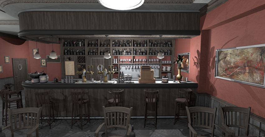
of the scene. To combat this, we remove some of the structure in The B ISTRO scene has, perhaps, the most spectacular results.
the image by randomizing the pattern choice in that interval. This At 60 FPS, our method looks almost broken, but at 240 FPS, our
π rendered images are integrated into a perceptually satisfactory ex-
reduces the flickering artifacts and crawlies. The constant γ = 40
was found empirically. Putting the above together yields the pixel perience. We urge the reader to look at the beer taps and the bar
ordering decision function ĝ(` f , α) that we use. The corresponding counter. This scene is ray traced at about 310 FPS. In the L IV-
function graph is shown in the right figure in Figure 10. ING ROOM scene (290 FPS), we see a large reduction in aliasing
with our method and TAA, compared to the vanilla rendering. This
On our website (Section 3), we include comparisons of the three
can be seen, for example, on the table. As the robot in C ERBERUS
rightmost decision functions in Figure 10 for three different camera
(260 FPS) runs, we see some flickering in the highlights for the
animations. The first camera has a motion direction 0 < α ≤ π4 − γ,
vanilla rendering. This is reduced both with TAA and with our
the second has a motion direction π4 − γ < α < γ + π4 , and the third
method, though with TAA, the highlights tend to disappear com-
has a motion direction π4 + γ ≤ α < π2 . With the first camera, we see
pletely. In C ERBERUS, the reflected motion vectors (enabled for
that the middle-left function yields the most satisfactory results,
our method) gives a positive effect in the form of a clearer reflec-
while the results with the third camera suggests that the middle-
tion. This scene also demonstrates the blur that arises without any
right function provides the best experience. In the case of the sec-
special handling of dynamic shadows cast on static objects.
ond camera, the best results are those stemming from randomiz-
ing the pattern selection. These examples support our decision of As a medium failure case, we have found that rapidly moving,
using the rightmost pixel ordering decision function illustrated in thin features are often hard to render well. To demonstrate this, we
c 2019 The Author(s)
Eurographics Proceedings c 2019 The Eurographics Association.P. Andersson et al. / Temporally Dense Ray Tracing
1.0 1.0 1.0 1.0
0.5 0.5 0.5 0.5
0 α 0 α 0 α 0 α
0 π/4 π/2 0 π/4 π/2 0 π/4 π/2 0 π/4 π/2
Figure 10: Four different alternatives for the per-tile pixel ordering decision function, ĝ(` f , α), based on the fractional part, ` f , of the
motion length, and the motion direction, α. Yellow color indicates that the hourglass pattern should be chosen, blue color indicates the
bowtie pattern, and green indicates that the choice between the two is random. We use the rightmost alternative.
have rendered H AIRBALL (290 FPS). The results can be found on terns, code optimization, theoretical explanations, and generalized
our website. TAA generates substantially more blur than both other motion vector computations.
methods and thin geometry may sometimes even disappear. One
case where aliasing is not reduced at all is shown in the bowtie ver- References
sus hourglass comparison (Section 3 on our website). For the clos-
[AMNA∗ 19] A KENINE -M ÖLLER T., N ILSSON J., A NDERSSON M.,
est chair at the bottom, the top curved edge has retained aliasing. BARRÉ -B RISEBOIS C., T OTH R., K ARRAS T.: Texture Level of De-
This is, however, a problem for all methods we compared. Another tail Strategies for Real-Time Ray Tracing. In Ray Tracing Gems, Haines
problem that is sometimes visible is what we call advancing fronts. E., Akenine-Möller T., (Eds.). Apress, 2019, ch. 20. 3
When an edge of an object belongs to a region classified as, say, [BFMZ94] B ISHOP G., F UCHS H., M C M ILLAN L., Z AGIER E. J. S.:
bowtie and the background of that edge belongs to hourglass, a tile Frameless Rendering: Double Buffering Considered Harmful. In Pro-
with an edge may be classified as hourglass and when the classifi- ceedings of SIGGRAPH (1994), pp. 175–176. 1
cation switches to bowtie, it is too late. This may manifest itself as [DER∗ 10] D IDYK P., E ISEMANN E., R ITSCHEL T., M YSZKOWSKI K.,
aliasing on the front of a moving edge. S EIDEL H.-P.: Perceptually-motivated Real-time Temporal Upsampling
of 3D Content for High-refresh-rate Displays. Computer Graphics Fo-
rum 29, 2 (2010), 713–722. 2
In a small user study with 35 subjects (33 men, two women), and
[DWWL05] DAYAL A., W OOLLEY C., WATSON B., L UEBKE D.:
an age span from 27 to 73 years, we showed three renderings next Adaptive Frameless Rendering. In Eurographics Symposium on Ren-
to each other. A high quality (256 SPP) rendering of B ISTRO at dering (2005), pp. 265–275. 1
240 FPS was shown in the middle. For each subject, we randomly [EM16] E L M ANSOURI J.: Rendering Tom Clancy’s Rainbow Six |
placed a rendering with 1 SPP at 60 FPS on either the left or right Siege. Game Developers Conference, 2016. 1, 2
side, and our technique at 240 FPS, on the other side. We excluded [HA90] H AEBERLI P., A KELEY K.: The Accumulation Buffer: Hard-
TAA in the user study since we wanted to focus our evaluation ware Support for High-quality Rendering. In Proceedings of SIGGRAPH
on the perceptual difference between 60 Hz and 240 Hz, and not (1990), pp. 309–318. 1
on the amount of blur. When asked to identify the rendering that [HEMS10] H ERZOG R., E ISEMANN E., M YSZKOWSKI K., S EIDEL H.-
best resembled the ground truth, 94% selected our technique, which P.: Spatio-Temporal upsampling on the GPU. In ACM SIGGRAPH Sym-
posium on Interactive 3D Graphics and Games (February 2010). 1
indicates a strong preference toward our method.
[Kar14] K ARIS B.: High Quality Temporal Supersampling. Advances in
Real-Time Rendering in Games, SIGGRAPH Courses, 2014. 1, 3
Another remarkable result is shown in the last link on our web-
site. There, we compare our method, at 240 FPS, to 60 and 240 FPS [KH01] K ELLER A., H EIDRICH W.: Interleaved Sampling. In Euro-
graphics Workshop on Rendering Techniques (2001), pp. 269–276. 1
vanilla rendering. In our opinion, our method is very close to vanilla
[KSM∗ 19] K IM J., S PJUT J., M C G UIRE M., M AJERCIK A.,
rendering at 240 FPS, which acts as a ground truth image in this B OUDAOUD B., A LBERT R., L UEBKE D.: Esports Arms Race: Latency
case. Recall that our method traces only 25% of the full frame’s and Refresh Rate for Competitive Gaming Tasks. In Vision Science So-
pixels each frame. ciety (2019). 1
[LSR17] L EIMKÜHLER T., S EIDEL H.-P., R ITSCHEL T.: Minimal
A general comment is that our method, due to its spatially sparse Warping: Planning Incremental Novel-view Synthesis. Computer
rendering, cannot produce fully temporally coherent image se- Graphics Forum 36, 4 (2017), 1–14. 4
quences. However, the images are produced at a much higher pace, [PSK∗ 16] PATNEY A., S ALVI M., K IM J., K APLANYAN A., W YMAN
highlights tend to stay in the images, and textures remain sharp. C., B ENTY N., L UEBKE D., L EFOHN A.: Towards Foveated Rendering
for Gaze-tracked Virtual Reality. ACM Transactions on Graphics 35,
TAA runs at a lower rate, provides blurry texturing and edges, and
6 (2016), 179:1–179:12. URL: http://doi.acm.org/10.1145/
even ghosting. What is best is subjective, but if higher frame rates 2980179.2980246, doi:10.1145/2980179.2980246. 1, 3
are needed in order to compete in esports, as mentioned in the in- [Rej13] R EJHON M.: PHOTOS: 60Hz vs 120Hz vs ULMB, May 2013.
troduction, our method would likely be a better choice. The inte- www.blurbusters.com/faq/60vs120vslb/. 2
gration of frames at 240 Hz is exploited by our algorithm, as we [Swe07] S WEET B. T.: The Impact of Motion-Induced Blur on Out-the-
have shown both for edge antialiasing and for improved clamping. Window Visual System Performance. In IMAGE (2007). 2
We believe our work shows promise, with many avenues for future [Whi80] W HITTED T.: An Improved Illumination Model for Shaded Dis-
work, including improved pattern selection, better sampling pat- play. Commununications of the ACM 23, 6 (1980), 343–349. 3
c 2019 The Author(s)
Eurographics Proceedings c 2019 The Eurographics Association.You can also read