TG 0530 - Sewer Network Hydraulic Design Considerations to Minimise Network Odour Impact - Sewer Network Hydraulic Design Considerations to ...
←
→
Page content transcription
If your browser does not render page correctly, please read the page content below

Engineering

Technical Guideline

TG 0530 - Sewer Network
Hydraulic Design
Considerations to Minimise
Network Odour Impact

Version: 1.0
Date: 5 February 2021
Status: Final

Document ID: SAWG-ENG-0530

© 2021 SA Water Corporation. All rights reserved. This document may contain
confidential information of SA Water Corporation. Disclosure or dissemination to
unauthorised individuals is strictly prohibited. Uncontrolled when printed or
downloaded.
TS 0530 – Sewer Network Hydraulic Design Considerations                    SA Water - Technical Guideline

Copyright
       This Guideline is an intellectual property of the South Australian Water Corporation. It is
       copyright and all rights are reserved by SA Water. No part may be reproduced, copied or
       transmitted in any form or by any means without the express written permission of SA Water.
       The information contained in this Guideline is strictly for the private use of the intended
       recipient in relation to works or projects of SA Water.
       This Guideline has been prepared for SA Water’s own internal use and SA Water makes no
       representation as to the quality, accuracy or suitability of the information for any other
       purpose.

Application & Interpretation of this Document
       It is the responsibility of the users of this Guideline to ensure that the application of information
       is appropriate and that any designs based on this Guideline are fit for SA Water’s purposes
       and comply with all relevant Australian Standards, Acts and regulations.
       Users of this Guideline accept sole responsibility for interpretation and use of the information
       contained in this Guideline. Users should independently verify the accuracy, fitness for
       purpose and application of information contained in this Guideline.
       Only the current revision of this Guideline should be used which is available for download
       from the SA Water website.

Significant/Major Changes Incorporated in This Edition
       Nil.
       This is the first issue of this Technical Guideline.

Revision 1.0 – February 2021               Document ID: SAWG-ENG-0530                              Page 2 of 50
For Official Use Only                                                   Uncontrolled when printed or downloaded
TS 0530 – Sewer Network Hydraulic Design Considerations                                 SA Water - Technical Guideline

Document Controls

Revision History

         Revision       Date        Author               Comments
            0.1         28 May      Jacobs               Draft for SA Water review
                        2020
            0.2         August      Jacobs               Final draft for SA Water review
                        2020
            0.3         September   Jacobs               Final
                        2020
            1.0         February    SA Water             Final for Issue
                        2021

       Template: Technical Guideline Version 6.00, 10/05/2016

Approvers
         Role                                                    Signature and Date
         Responsible Discipline Lead                                                                              8 /0 2 /2 0 2 1

         Mark Papadimitriou

                                                                  X         M a r k P a p a d im itr io u
                                                                  S ig n e r's N a m e

                                                                  S ig n e d b y: P A 0 0 4 1 1 7

         Manager Engineering Quality and Innovation                                                               9 /0 2 /2 0 2 1
         Matthew Davis

                                                                  X
                                                                  S ig n e r's N a m e

                                                                  S ig n e d b y: D A 0 0 3 6 8 1

         Senior Manager Engineering Services                                                                       9 /0 2 /2 0 2 1

         Richard Gray

                                                                  X
                                                                   S ig n e r 's N a m e

                                                                   S ig n e d b y : G R 0 0 1 9 6 4

Reviewers
         Role                                           Name                                          Revision   Review Date
         Jacobs Technical Lead                          Josef Cesca                                     0.1      28 May 2020
         SAW Wastewater Engineering Review              Teresa Qiu                                      0.1      29 June 2020
         Jacobs Technical Lead                          Josef Cesca                                     0.2      August 2020
         SAW Wastewater Engineering Review              Teresa Qiu                                      0.2      August 2020
         Jacobs Technical Lead                          Josef Cesca                                     0.3      September
                                                                                                                    2020

Revision 1.0 – February 2021                 Document ID: SAWG-ENG-0530                                            Page 3 of 50
For Official Use Only                                                             Uncontrolled when printed or downloaded
TS 0530 – Sewer Network Hydraulic Design Considerations                   SA Water - Technical Guideline

Executive Summary
       This Technical Guideline outlines sewer network design considerations for minimisation of
       network odour impacts. It only considers odour generation and is not intended as a hydraulic
       design standard. Any sewer design undertaken by SA Water shall follow all the relevant
       procedures, with hydraulic design requirements taking precedent over this Guideline
       document.
       Designing a sewer network that has no odour is prohibitively expensive but the effort made to
       reduce and manage the causes of odour and corrosion during design can reduce some of
       the impacts and will provide considerably longer term benefit to SA Water.
       The cause of sewer odour and corrosion problems starts with the formation of sulphide in the
       wastewater. Sulphide formation is a biological process that reduces sulphates and other
       sulphur compound to sulphide under anaerobic conditions. Anaerobic conditions exist in
       rising mains, siphons, in the sediment and deeper levels of sewers and wet wells. The sulphide
       formed is subsequently released to the sewer headspace, where it can cause corrosion of
       concrete and metals or be released to the atmosphere where it may cause odour problems.
       The preferred approach in sewer design for odour control is:
       1.      Prevention of sulphide formation
       1.      To release the sulphides to atmosphere in a location where there will not be adverse
               impacts if possible (to remove sulphides from the system)
       2.      To keep the sulphide in the liquid phase by reducing turbulence and maintaining
               adequate sewer head space to allow air flow with minimal restriction
       3.      If the above are insufficient or not possible, some form of control to prevent corrosion
               and odour problems.
       Minimising sulphide formation is the first step in managing odour and corrosion for sewer
       design, and key considerations are:
       • Controlling the hydraulic retention time in rising mains and wet wells to avoid anaerobic
         conditions
       • Achieving adequate sewage velocity to achieve natural reaeration, scouring of
         sediments, and striping for minimising slime layers on pipes
       Once formed, the sulphide will be released to the sewer headspace at a faster or lower rate
       depending on the level of turbulence. Rising main discharge locations, steep slopes and
       drops all promote turbulence and faster sulphide release to the sewer headspace. Ideally the
       air in the sewer headspace should be released to atmosphere at these locations to prevent
       the build-up of H2S levels in the network. If this is not possible due to the sensitive nature of the
       locations, adopting strategies to reduce turbulence, ensure that the sewer headspace is not
       too restricted (and does not surcharge) and to allow the free flow of sewer air will be
       required. The reason for this is that restriction in headspace will increase the pressure which
       will force air out at uncontrolled locations. Managing the release of sewer gases requires
       effective containment so that gases are only released at designed locations, such as educts.
       The Table below provides a quick reference guide to the sewer network design
       considerations for minimisation of network odour impacts that are covered in this Guideline.

Revision 1.0 – February 2021             Document ID: SAWG-ENG-0530                               Page 4 of 50
For Official Use Only                                                  Uncontrolled when printed or downloaded
TS 0530 – Sewer Network Hydraulic Design Considerations SA Water - Technical Guideline
Design Consideration Reference
Process of sulphide formation and corrosion Section 5.2
Odour risk level related to HRT and sulphide concentration (for high Table 5-2
level analyses only)
Quantifying Odour Risk Section 5.6
Hydraulic drop design with internal and external drop pipes Figure 6-2
Applicability of vortex drop structures Section 6.3
Design requirements for vortex drop structures Section 6.3
Design Standards to avoid hydraulic jumps and surges Section 7.4
Gravity sewer design to minimise sulphide generation Section 8.3.1
Rising main design to minimise sulphide generation Section 8.3.2
Design of rising main discharge manholes Section 9
Rising main discharge design to promote non-turbulent conditions Table 9-1
Design of SPS wet well/control manhole incoming sewer discharge Section 10
Requirements for seals on wet wells and manhole covers Section 11.1
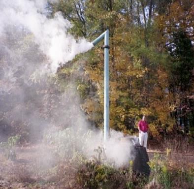
Design of wet well inducts and educts Section 12
Design of collar type rain guard for a stack Figure 12-1
Revision 1.0 – February 2021 Document ID: SAWG-ENG-0530 Page 5 of 50
For Official Use Only Uncontrolled when printed or downloaded
TS 0530 – Sewer Network Hydraulic Design Considerations                                           SA Water - Technical Guideline

Contents
       1       Introduction ........................................................................................................ 9
       1.1        Purpose .......................................................................................................... 9
       1.2         Glossary ......................................................................................................... 9
       1.3         References .................................................................................................. 10
       1.3.1         Australian and International .................................................................. 10
       1.3.2         SA Water Documents ............................................................................. 10
       1.4         Definitions .................................................................................................... 10

       2       Scope ............................................................................................................... 11

       3       Odorous Compounds in Sewers ..................................................................... 12

       4       High Level Design Overview ........................................................................... 14

       5       Hydraulic Retention Time and Odour Risk ..................................................... 15
       5.1       Introduction ................................................................................................. 15
       5.2         Hydrogen Sulphide Formation ................................................................... 15
       5.3         Precursors for Sulphide Generation ........................................................... 17
       5.4         Risks of Sulphide Generation ...................................................................... 19
       5.5         Impacts of HRT and Odour Risk.................................................................. 19
       5.6         Quantifying Odour Risk ............................................................................... 20

       6       Hydraulic Drops and Vortex Droppers ........................................................... 23
       6.1       Introduction ................................................................................................. 23
       6.2       Hydraulic Drops ........................................................................................... 23
       6.3       Vortex Droppers .......................................................................................... 24

       7       Hydraulic Jumps and Surges .......................................................................... 28
       7.1       Introduction ................................................................................................. 28
       7.2       Hydraulic Jump ........................................................................................... 28
       7.3       Hydraulic Surges .......................................................................................... 29
       7.4         Design Standards ........................................................................................ 30

       8       Velocities, Gradient and Turbulence in Rising Mains and Gravity Sewers . 34
       8.1         Introduction ................................................................................................. 34
       8.2         Impacts of Sewer Velocities for Scouring and for Reaeration of Sewage34
       8.3         Recommended Sewage Velocities and Gradients to Minimise Sulphide
                   Generation .................................................................................................. 34
       8.3.1          Gravity Sewers ........................................................................................ 35
       8.3.2          Rising Mains ............................................................................................. 38
       8.4         Impact of Sewage Velocities for Slime Stripping and Release of H2S .... 40

       9       Rising Main Discharge Manhole Design Considerations .............................. 42

       10      Sewage Pump Station Wet Well/Control Manhole Incoming Sewer Discharge
               Arrangement.................................................................................................... 44

       11 Seals ................................................................................................................. 46
       11.1 Wet Well and Manhole Covers .................................................................. 46
Revision 1.0 – February 2021                        Document ID: SAWG-ENG-0530                                                  Page 6 of 50
For Official Use Only                                                                        Uncontrolled when printed or downloaded
TS 0530 – Sewer Network Hydraulic Design Considerations                                         SA Water - Technical Guideline

       11.2        Water Seals .................................................................................................. 46

       12      Design of Wet Well Inducts and Educts.......................................................... 47

       13      Gravity Sewer Surcharging Conditions and Performance Criteria .............. 49

       14      References ....................................................................................................... 50

List of figures
       Figure 3-1 Physiological Effects of H2S [4]................................................................ 13
       Figure 5-1 Schematic of sewer processes driving H2S and corrosion ................... 15
       Figure 5-2 Liquid-Phase Sulphide Distribution vs pH ............................................... 16
       Figure 5-3 Progression of microbial corrosion of sewer pipe ................................. 17
       Figure 6-1 Hydraulic Drop......................................................................................... 23
       Figure 6-2 Typical Installations of Hydraulic Drop with Internal and External Drop Pipes
               ...................................................................................................................... 24
       Figure 6-3 Vortex Dropper ........................................................................................ 25
       Figure 6-4 Typical Vortex Dropper with Air Return .................................................. 27
       Figure 7-1 Hydraulic Jump ....................................................................................... 28
       Figure 7-2 Air Flow Movement at Hydraulic Jump ................................................. 28
       Figure 7-3 Sewer Design to Avoid Hydraulic Jumps ............................................... 29
       Figure 7-4 Uncontrolled Air Release Caused by Hydraulic Surge ......................... 30
       Figure 7-5 Streamlining branch sewer connections on trunk mains ..................... 31
       Figure 7-6 Side chamber for merging flow from branch sewer ............................ 31
       Figure 7-7 Streamlined Junction [4] ......................................................................... 32
       Figure 7-8 Potential Solutions to a Hydraulic Jump in a Manhole ........................ 33
       Figure 8-1 Critical Sewer Slopes for Slime Control [3] ............................................. 37
       Figure 8-2 Minimum Sewer Velocities for Slime Control [3] .................................... 37
       Figure 8-3 Guide for Estimate Sulphide Generation Potential [9] ......................... 38
       Figure 8-4 Minimum Velocities for Slime Control in Rising Mains [3] ...................... 40
       Figure 8-5 Detention Time per 100 m of Rising Main .............................................. 40
       Figure 11-1 Connection of residences to a trunk sewer via reticulation sewer with
               water seal .................................................................................................... 46
       Figure 12-1 Collar-type rain guard for a stack ....................................................... 48

List of tables
       Table 3-1 Properties of the Most Predominant Odorous Compounds in Sewers . 12
       Table 3-2 Established Limits for Hydrogen Sulphide in the Workplace ................. 13
       Table 5-1 Factors Affecting Sulphide Generation in Sewers [9] ............................ 18
       Table 5-2 HRT in Rising Mains/Wet Wells and Odour Risk ....................................... 20
       Table 5-3 Odour Risk ................................................................................................. 22
       Table 6-1 Risks and Benefits of Vortex Droppers ..................................................... 25
       Table 6-2 Drop Requirements [1] ............................................................................. 26
       Table 8-1 Absolute Minimum Grades Recommended for Self-Cleansing [1] ...... 35
Revision 1.0 – February 2021                       Document ID: SAWG-ENG-0530                                                 Page 7 of 50
For Official Use Only                                                                      Uncontrolled when printed or downloaded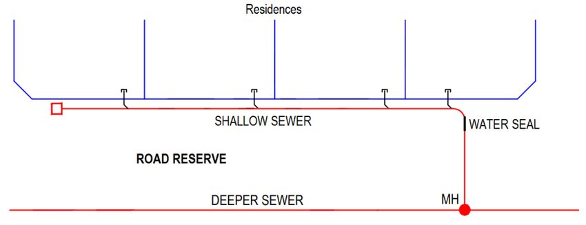
TS 0530 – Sewer Network Hydraulic Design Considerations               SA Water - Technical Guideline

       Table 8-2 Recommended Gravity Sewer Design Methods ................................... 36
       Table 9-1 Rising Main Discharge Promoting Non-turbulent Conditions [3] .......... 43

Revision 1.0 – February 2021          Document ID: SAWG-ENG-0530                              Page 8 of 50
For Official Use Only                                              Uncontrolled when printed or downloaded
TS 0530 – Sewer Network Hydraulic Design Considerations SA Water - Technical Guideline
1 Introduction
SA Water is responsible for operation and maintenance of an extensive amount of sewerage
infrastructure.
This Guideline has been developed to outline sewer network design considerations to
minimise network odour impacts.
1.1 Purpose
The purpose of this Guideline is to provide guidance for use in the design of sewer assets to
minimise network odour impacts.
This Guideline only considers odour generation and is not intended as a hydraulic design
standard. Any sewer design undertaken by SA Water shall follow all the relevant procedures,
with hydraulic design requirements taking precedent over this Guideline document.
1.2 Glossary
The following glossary items are used in this document:
Term Description
BOD Biochemical Oxygen Demand
BWL Bottom Water Level
CO2 Carbon Dioxide
DMDS Dimethyl Disulphide
DMS Dimethyl Sulphide
DO Dissolved Oxygen
HRT Hydraulic Retention Time
H2S Hydrogen Sulphide
H2SO4 Sulphuric Acid
MM Methyl Mercaptan
ORP Oxidation Reduction Potential
ou Odour Unit
ppb Parts Per Billion
ppm Parts Per Million
SA Water South Australian Water Corporation
SPS Sewage Pump Station
SRB Sulphate Reducing Bacteria
STEL Short Term Exposure Limit
RM Rising Main
TS SA Water Technical Standard
TG SA Water Technical Guideline
TWA Time Weighted Average
VFA Volatile Fatty Acids
WSAA Water Services Association of Australia
Revision 1.0 – February 2021 Document ID: SAWG-ENG-0530 Page 9 of 50
For Official Use Only Uncontrolled when printed or downloadedTS 0530 – Sewer Network Hydraulic Design Considerations SA Water - Technical Guideline
1.3 References
1.3.1 Australian and International
The following table identifies Australian and International standards and other similar
documents referenced in this document:
Number Title
WSA 02- Sewerage Code of Australia, WSA 02—2002-2.2 (Sydney Water Edition, Version 4), Water
2002-2.2 Services Association of Australia (WSAA), 2017.
WSA 04- Sewage Pumping Station Code of Australia, WSA 04—2005-2.1 (Sydney Water Edition),
2005-2.1 Water Services Association of Australia (WSAA), 2012.
Hydrogen Sulphide Control Manual: Septicity, Corrosion and Odour Control in Sewerage
Systems. Volume 1, Technical Standing Committee on Hydrogen Sulphide Corrosion in
Sewerage Works, Melbourne and Metropolitan Board of Works, 1989.
US EPA Design Manual - Odour & Corrosion Control in Sanitary Sewerage Systems &
Treatment Plants, US EPA, 1995.
Water Security Agency of Saskatchewan Sewage Works Design Standard, 2012.
City of Omaha Wastewater Collection Systems Design Manual (Pre-Final), 2018.
1.3.2 SA Water Documents
The following table identifies the SA Water standards and other similar documents referenced
in this document:
Number Title
Standard on Odour Control in Wastewater Networks and Wastewater Treatment Plants,
Version 0.01, Draft, SA Water 24/12/15.
TG 0531 Gravity Network Ventilation Design
1.4 Definitions
The following definitions are applicable to this document:
Term Description
Hydraulic Drop SA defines a hydraulic drop as any difference of greater than 0.3 m in
water level between sections of pipes
Hydraulic Jump A jump or standing wave formed when the depth of flow of water
changes from supercritical to subcritical state
SA Water’s Representative The SA Water representative with delegated authority under a
Contract or engagement, including (as applicable):
• Superintendent’s Representative (e.g. AS 4300 & AS 2124 etc.)
• SA Water Project Manager
• SA Water nominated contact person
Responsible Discipline Lead The engineering discipline expert responsible for TG 0530 defined on
page 3 (via SA Water’s Representative)
Revision 1.0 – February 2021 Document ID: SAWG-ENG-0530 Page 10 of 50
For Official Use Only Uncontrolled when printed or downloadedTS 0530 – Sewer Network Hydraulic Design Considerations SA Water - Technical Guideline
2 Scope
This Technical Guideline provides guidance on sewer network hydraulic design to minimise network
odour impacts. Details of the main odorous compounds in sewage are outlined, followed by a
high-level design overview which presents the recommended design approach to minimise
network odour impacts. Each of the following design aspects are then outlined in a separate
section in the Guideline:
1. Hydraulic retention time (HRT) and its impact on sulphide generation and odour
production
2. Hydraulic drops and vortex droppers
3. Hydraulic jumps and surges
4. Sewage velocities, sewer gradient and turbulence in rising mains and gravity sewers
5. Rising main discharge manhole design considerations
6. Sewage pump station (SPS) wet well/control manhole incoming sewer discharge
arrangement
7. Seals on wet well covers
8. Design of wet well inducts and educts
9. Gravity sewer surcharging conditions and performance criteria
It is noted that this Guideline considers hydrogen sulphide (H2S) in terms of its odour impacts only.
Revision 1.0 – February 2021 Document ID: SAWG-ENG-0530 Page 11 of 50
For Official Use Only Uncontrolled when printed or downloadedTS 0530 – Sewer Network Hydraulic Design Considerations SA Water - Technical Guideline
3 Odorous Compounds in Sewers
This Section outlines the chemical compounds found in sewers which are known odorants,
along with their characteristics and how they are generated.
There are many different compounds that occur in sewer air, ranging from those with no
odour to those that are highly odorous. The odorous compounds come from a range of
chemical species including mercaptans, amines, aldehydes, volatile fatty acids (VFAs), and
H2S which fits into no specific group.
Despite the variety, only a handful of odorants occur frequently and with a significant
presence. H2S and methyl mercaptan (MM) are the most predominant, followed by dimethyl
sulphide (DMS) and dimethyl disulphide (DMDS). The properties of these compounds are
shown in Table 3-1.
Table 3-1 Properties of the Most Predominant Odorous Compounds in Sewers
Odorant Odour Description Odour Means of Generation
Threshold
Hydrogen rotten eggs 0.51 ppbv • Bacteria in wastewater reduce
Sulphide (low) sulphides to H2S, which is then
(H2S) released to the air phase, especially
during turbulence or under low pH.
Methyl rotten cabbage 0.077 ppbv • Generated by humans and released
Mercaptan (very low) in faeces.
(MM) • Anaerobic decomposition of sulphur-
containing proteins.
Dimethyl disagreeable 3.0 ppbv • Produced by the bacterial
Sulphide rotten vegetable / metabolism of methyl mercaptan in
(DMS) decayed sewers.
cabbage • Forms under anaerobic conditions.
Assumed that rising mains, siphons
and sewage pump stations (SPS)
would favour formation.
Dimethyl garlic-like 0.022 ppbv • Forms under anaerobic conditions.
Disulphide (very low) Assumed that rising mains, siphons
(DMDS) and SPSs would favour formation.
H2S is one of the most predominant odorous compounds in sewage. The physiological effects of H2S
are summarised in Figure 3-1, and established limits for workplace H2S exposure are provided in
Table 3-2 for information only, but will not be considered further. Designers should note that very low
concentrations of this gas can cause serious health hazards, and the ability to sense it by smell is
quickly lost as concentrations increase. Death has resulted from concentrations of 300 ppm by
volume in air. [8] Such concentrations can be obtained in an enclosed chamber with high
turbulence, from wastewater containing 2 mg/l of dissolved sulphide at a pH of 7.0. [4]
Revision 1.0 – February 2021 Document ID: SAWG-ENG-0530 Page 12 of 50
For Official Use Only Uncontrolled when printed or downloadedTS 0530 – Sewer Network Hydraulic Design Considerations SA Water - Technical Guideline
ppm
0.1
0.2
Odour threshold
3
Rotten egg
Offensive odour
odor alarm
10
Headache, nausea,
throat and eye irritation
Threshold of
50
serious eye injury
Eye injury
Loss of sense
100
of smell Conjunctivitis,
respiratory tract
irritation, olfactory
paralysis
300
Imminent life
threat Pulmonary edema
500
Strong nervous system
stimulation, apnea
1,000
Immediate collapse with
Death
respiratory paralysis
Figure 3-1 Physiological Effects of H2S [4]
Table 3-2 Established Limits for Hydrogen Sulphide in the Workplace
Metric SafeWork Australia Limit
(ppm)
Eight Hour Time Weighted Average (TWA) 10
Short Term Exposure Limit (STEL) 15
Revision 1.0 – February 2021 Document ID: SAWG-ENG-0530 Page 13 of 50
For Official Use Only Uncontrolled when printed or downloadedTS 0530 – Sewer Network Hydraulic Design Considerations SA Water - Technical Guideline
4 High Level Design Overview
This Section outlines a high-level design approach that should be used to minimise network
odour impacts. It outlines the prioritisation strategy for adopting the recommendations in the
following sections based on specific circumstances.
Designing a sewer network that has no odour will be prohibitively expensive but the effort
made to reduce and manage the causes of odour and corrosion during design can reduce
some of the impacts and will provide considerably longer term benefit to SA Water.
The cause of sewer odour and corrosion problems starts with the formation of sulphide in the
wastewater which is subsequently released to the sewer headspace. In the sewer headspace
it will cause corrosion of concrete and metals or be released to the atmosphere where it may
cause odour problems. Sulphide formation is described in Section 5.2. It is a biological process
that reduces sulphates and other sulphur compound to sulphide under anaerobic conditions.
Anaerobic conditions exist in rising mains, siphons, in the sediment and deeper levels of
sewers and wet wells. Standards for the hydraulic retention time (HRT) in rising mains and wet
wells to quantify impacts of anaerobic conditions are provided in Section 5.5. Standards for
ensuring the velocity of the sewage is such that;
• natural reaeration;
• scour of sediments; and
• striping for minimising slime layers on pipes;
occur should be a key consideration to minimise sulphide formation and are described in
Section 8. Minimising sulphide formation is the first step in managing odour and corrosion for
sewer design.
Once formed the sulphide will be released to the sewer headspace at a faster or lower rate
depending on the level of turbulence. Rising main discharge locations, steep slopes and
drops all promote turbulence and faster sulphide release to the sewer headspace. Ideally the
air in the sewer headspace should be released to atmosphere at these locations to prevent
the build-up of H2S levels in the network. If this is not possible due to the sensitive nature of the
locations, adopting strategies to reduce turbulence, ensure that the sewer headspace is not
too restricted (and does not surcharge) and to allow the free flow of sewer air will be
required, and are described in Sections 7, 9 and 13. The reason for this is that restriction in
headspace will increase the pressure which will force air out at uncontrolled locations.
Managing the release of sewer gases requires effective containment so that gases are only
released at designed locations. Containment is discussed in Section 11, and inducts and
educts for ventilation of wet wells are discussed in Section 12.
Options for reducing impacts of hydraulic drops are discussed in Section 6.
In summary, achieving scour and shear velocities to prevent/ minimise sulphide generation,
should be the first priority in sewer design. Risk of sulphide release in sensitive areas should
then be evaluated on a case by case basis for areas such as rising main discharge locations
or other areas where sulphide will be high. The preferred approach for these areas should be:
10. To release the sulphides to atmosphere in a location where there will not be adverse
impacts if possible (to remove sulphides from the system)
11. To keep the sulphide in the liquid phase by reducing turbulence and maintaining
adequate sewer head space to allow air flow with minimal restriction
12. If the above are insufficient or not possible, some form of control if required.
Put succinctly, the order or priority in sewer design for odour control should be prevention of
sulphide formation, mitigation of release to sensitive locations then control to prevent
corrosion and odour problems.
Revision 1.0 – February 2021 Document ID: SAWG-ENG-0530 Page 14 of 50
For Official Use Only Uncontrolled when printed or downloadedTS 0530 – Sewer Network Hydraulic Design Considerations SA Water - Technical Guideline
5 Hydraulic Retention Time and Odour Risk
5.1 Introduction
This Section considers HRT and its impact upon sulphide generation and odour production. It
outlines the following:
• Formation of H2S
• Precursors for sulphide generation
• Explanation of odour risk and how it is impacted by HRT
• Risks of sulphide generation, and what constitutes low, medium and high risk
• Quantification of odour risk
5.2 Hydrogen Sulphide Formation
H2S formation begins in the wastewater stream. Colonies of anaerobic sulphate reducing
bacteria (SRB) active in biofilm layers that line submerged sewer walls reduce sulphates and
oxidise biodegradable organic carbon producing H2S, VFAs and carbon dioxide. H2S is
generally the most prevalent sewer gas and generally the greatest contributor to odour risk
from sewers. The processes described are shown in Figure 5-1.
Figure 5-1 Schematic of sewer processes driving H2S and corrosion
Sulphide (S2-)
in the wastewater can combine with hydrogen (H+) to form HS- and H2S. The
amounts of the three-sulphide species present (H 2S, HS-, and S2-) are also pH dependent. As
oxidation-reduction potential (ORP) indicates stronger anaerobic conditions in the
wastewater and the longer the wastewater is anaerobic, more VFAs are formed which lower
the pH of the wastewater. The relative distribution of the three species, as a function of pH, is
presented in Figure 5-2. As can be seen, the amount of H2S is very sensitive to pH. At a pH of 7,
Revision 1.0 – February 2021 Document ID: SAWG-ENG-0530 Page 15 of 50
For Official Use Only Uncontrolled when printed or downloadedTS 0530 – Sewer Network Hydraulic Design Considerations SA Water - Technical Guideline
50% is present as H2S. At pH < 5.5, almost all sulphide is H2S (> 97%) while at pH > 8.5, less than
3% is present as H2S.
Figure 5-2 Liquid-Phase Sulphide Distribution vs pH
H2S and carbon dioxide (CO2) are transported through the biofilm into the wastewater stream
where some is volatilised into the sewer headspace when the pH is below about 8.5. This H 2S
can then be oxidised to sulphuric acid by aerobic biomass on concrete and steel surfaces
which leads to corrosion.
Sewage detention times in rising mains, wastewater characteristics and temperature are the
common parameters that impact sulphide levels, and sulphide transfer to gas phase (as H 2S)
is mostly driven by turbulence and pH with some temperature impacts.
Sulphuric acid (H2SO4) forms as the H2S leaves the wastewater, enters the air in the
headspace between the wastewater and the top (crown) of the sewer pipe, and diffuses
into the condensation present on the crown and walls of the gravity sewer. Along the crown
and pipe walls, the H2S is oxidised by the action of Thiobacillus bacteria to form sulphuric
acid. Sulphuric acid formation is initially a slow rate process on new concrete due to the high
alkalinity of the concrete itself (pH ranging from 11 to 13). Thiobacillus are unable to survive
under high pH conditions. Aging of the concrete results in a decrease of surface pH to
between 7 and 8. At this pH, a different species of Thiobacillus colonises the concrete
surface, further reducing the pH of the condensate to less than 5. From this point corrosion
proceeds faster if other environmental agents (H2S, humidity and temperature) are present.
Figure 5-3 summarises the processes of bacteria colonising the pipe, the change in pipe pH,
and the damage done to the pipe.
Revision 1.0 – February 2021 Document ID: SAWG-ENG-0530 Page 16 of 50
For Official Use Only Uncontrolled when printed or downloadedTS 0530 – Sewer Network Hydraulic Design Considerations SA Water - Technical Guideline
Figure 5-3 Progression of microbial corrosion of sewer pipe
5.3 Precursors for Sulphide Generation
Many variables directly or indirectly affect sulphide generation in sewers, and hence H2S
release, and sulphuric acid corrosion. These variables are summarised in Table 5-1 and
discussed further below. [9]
Revision 1.0 – February 2021 Document ID: SAWG-ENG-0530 Page 17 of 50
For Official Use Only Uncontrolled when printed or downloadedTS 0530 – Sewer Network Hydraulic Design Considerations SA Water - Technical Guideline
Table 5-1 Factors Affecting Sulphide Generation in Sewers [9]
Factor Effect
Wastewater Characteristics
Dissolved oxygen (DO) Low DO favours proliferation of anaerobic bacteria and subsequent
sulphide generation.
Biochemical oxygen High soluble BOD encourages microbial growth and DO depletion.
demand
(BOD)(organic
strength)
Temperature High temperatures increase microbial growth rate and lowers DO
solubility.
pH Low pH favours shift to dissolved H2S gas.
Presence of sulphur Sulphur compounds required for sulphide generation. The
compounds concentrations of these compounds can be very significant when
they are the result of groundwater and sea-water infiltration and in
some cases due to trade waste.
Sewer System Characteristics
Slope, velocity and Affects degree of reaeration, solids deposition, H2S release, thickness
change in direction of slime layer.
Note that change in direction can cause similar effects, as velocity
suddenly decreases and turbulence increases.
Hydraulic Drops Can promote H2S release, turbulence and may cause outgassing.
Refer to section 6.2.
Turbulence Same effect as slope/velocity.
Surcharging Reduces oxygen transfer and promotes sulphide generation, will not
corrode while surcharged.
Can also cause foul air release as the sewer headspace is restricted,
causing pressurisation and driving air out of the sewer.
Presence of force The full pipe will prevent reaeration and provides a large wet area
mains and inverted for biofilm growth which can lead to H2S formation under anaerobic
siphons conditions. The inlet end will restrict sewer airflow causing it to be
released. The turbulent discharge end will cause release of H2S.
Sewer pipe materials Corrosion resistance of pipe materials varies widely. Porous materials,
such as concrete, favour biofilm attachment, while comparatively
less porous materials such as plastic support a smaller a biofilm and
the biofilm is more easily scoured off. However, the reduced biofilm
in the headspace means less H2S is oxidised to H2SO4. This can result
in higher H2S concentrations downstream.
Concrete alkalinity Higher alkalinity reduces corrosion rate.
Accumulated grit and Slows wastewater flow, traps organic solids.
debris
For H2S to be formed, the wastewater must be anaerobic. In properly designed gravity
sewers, the velocity of the sewage is such that natural reaeration occurs from the
atmosphere in the sewer, helping to replenish any losses of oxygen due to microbial activity.
Certain structures and flow conditions often create turbulence of the wastewater, increasing
the rate of reaeration and helping to maintain aerobic conditions. Sources of turbulence
include:
• Manholes with flows dropping in from the side
• Manholes with flows colliding
• Metering flumes
Revision 1.0 – February 2021 Document ID: SAWG-ENG-0530 Page 18 of 50
For Official Use Only Uncontrolled when printed or downloadedTS 0530 – Sewer Network Hydraulic Design Considerations SA Water - Technical Guideline
• Drops in the line
• Sections with steep slopes
• Rising main discharges. [9]
• Sharp changes in pipe direction
Under certain conditions oxygen is depleted faster than it is supplied, causing a change from
aerobic to anaerobic conditions. Such conditions can occur in the following:
• Gravity sewers with low sewage velocities or long detention times
• Rising mains which convey wastewater through a full pipe under pressure with no
opportunity for reaeration
• Wet wells of sewage pump stations (SPS) having detention times sufficiently long as to
cause oxygen depletion due to uptake by bacteria
• Other structures or processes where wastewater is detained under near-stagnant
conditions with insufficient opportunity for reaeration
• Sections of sewer that can lead to significant solids deposition over time
• Industrial discharges with high concentrations of BOD
5.4 Risks of Sulphide Generation
The major risks related to sulphide build-up in sewers are:
• Corrosion of sewer structures and equipment
• Odour nuisance
• Health impacts on sewer workers
Corrosion of sewer structures and equipment can be significant, even at low H2S
concentrations. It can lead to pipe or even street collapses resulting from sewer pipe failure,
as well as premature replacement or rehabilitation of pipes, manholes, lift stations and SPSs.
Corrosion also compromises structural integrity by corroding equipment, pipe and equipment
supports, storage tanks, and guard rails, walkways, and grating. Electrical components (e.g.
brushes, switches, relays), process instrumentation, air conditioning and ventilation units, and
computer systems at SPS and lift stations are particularly vulnerable to H 2S corrosion. Corrosion
causes increased maintenance requirements, poor reliability of control systems and often
premature replacement or rehabilitation of assets is required.
H2S is recognisable to receptors in the vicinity of air release points from the sewer due to its
rotten egg character. The release of sewer odour results in odour complaints from sensitive
receptors. Ongoing odour releases from a sewer can cause reduced liveability, and may
result in a poor public perception of SA Water, as well as failure to comply with environmental
license requirements and possible fines
H2S generated in sewers also has potential health impacts on workers. High H2S levels under
manhole covers can cause operator/s to become unwell or even die due to inhaling high
levels when covers are opened or, entering a confined space without appropriate ventilation
and safety precautions.
5.5 Impacts of HRT and Odour Risk
Controlling sulphide production will assist in minimising odour risks associated with sewers. As
HRT in sewers and rising mains increases, the oxygen consumption increases, the ORP
decreases, and organic matter becomes increasingly solubilised. These conditions favour the
activity of the SRB, which generate odour and can cause corrosion. Thus, in the design of
collection systems, minimising HRT can limit the activity of the bacteria and thus the rate of
sulphide production. [4]
Revision 1.0 – February 2021 Document ID: SAWG-ENG-0530 Page 19 of 50
For Official Use Only Uncontrolled when printed or downloadedTS 0530 – Sewer Network Hydraulic Design Considerations SA Water - Technical Guideline
However, sulphide production itself is not of major concern in terms of odour. Sulphides in
sewage only have the potential to pose an odour risk if they leave the liquid phase and enter
the vapour phase as H2S. Sulphides generally leave the vapour phase as a result of
turbulence or when pH is lower than 8.5 (which is generally the case).
Odour release from sewers is a part of their operation and so forms part of their design;
educts allow air to escape where forces pressure the headspace, and inducts allow air in to
facilitate ventilation and sewer reaeration. Odour from sewers only poses a risk if foul air is
released from the sewer and there are nearby sensitive receptors or operators are affected.
The presence of odour where there is minimal to no risk of receiving odour complaints is
generally of little concern. However, where there are sensitive receptors or there is a need for
operators to access the sewer by cracking manholes thus releasing odour, the presence of
H2S poses an odour risk.
Table 5-2 below provides a general indication of the odour risk from sewers structures such as
rising mains and wet wells at different HRTs and sulphide levels. The odour risk assumes that
foul air is released from the sewer headspace and there are nearby sensitive receptors. It is
noted that the sulphide concentrations shown do not necessarily occur at the associated
HRTs, as this will be system dependent. The sulphide concentration and HRT are risk indicators;
it is not necessary for both conditions shown in the table to exist in order to determine the risk
level – either indicator can be used. These indicators are intended for high-level analyses,
flagging areas where further investigation should occur.
Table 5-2 HRT in Rising Mains/Wet Wells and Odour Risk
Risk Indicators
Odour Risk Sulphide Concentration Hydraulic Retention Time
Level (mg/L)1 (Hours)2
Low 4
Notes
1. Hvitved Jacobsen, 2002 [17]
2. It is recommended that HRT is calculated using ADWF and minimum overnight flows.
Recommended HRTs for the design of pump stations are detailed in Section 10.
While the design of a pump station influences the HRT, sometimes an idea arises that involves
reducing odours without additional costs by changing the operational times of the pumps. In
the case where pumps run only a few times a day, the adjustments seek to increase the
frequency of pump operation. There are pros and cons to doing this. Unfortunately, though,
for a single line rising main there is no difference in the HRT. Running the pump longer and less
often means incoming wastewater spends more time in the wet well. Conversely, running the
pump more often but for shorter periods means that wastewater spends more time in the
rising main than the wet well.
This is not to say that how the pumps are operated will not affect odour risk, but that it will not
make any difference to the HRT, which is ultimately determined by the rising main size.
Running the pump longer, less frequently will help scour both the rising main and downstream
gravity sewer, though it may also cause foul air to be released if the gravity pipe experiences
a surge. Running the pump for less time, more often will avoid surging but may encourage
biofilm growth and sediments to build up.
5.6 Quantifying Odour Risk
As indicated above, odour problems occur when sulphide emissions leave the sewer
atmosphere in the form of H2S. The amount of gas released determines the severity of odour
risk, and the public’s perception of odour is related to the following factors, referred to as the
FIDOL factors:
Revision 1.0 – February 2021 Document ID: SAWG-ENG-0530 Page 20 of 50
For Official Use Only Uncontrolled when printed or downloadedTS 0530 – Sewer Network Hydraulic Design Considerations SA Water - Technical Guideline
• Frequency of the occurrence
• Intensity of the odour
• Duration of exposure to the odour
• Offensiveness of the odour
• Location
Odour risks are generally higher for new developments for the following reasons:
• Initially developing areas only having a low number of connections, causing long HRT
which results in higher sulphides
• Proximity to sensitive receptors, who have invested in new properties and are more
sensitive to odour issues
• Sometimes backlog developments result in a daisy chain arrangement of pump stations,
or use pressure sewers, both of which causes long HRT under anaerobic conditions
In order to quantify odour risk from a sewer network or asset, an odour risk assessment should
be undertaken to rank the risk and determine a suitable approach to manage odour risks.
This risk assessment should consider the following:
• Proximity to sensitive receptors
• Upstream HRT in rising mains noting that multiple rising mains in series can have an
accumulative effect.
• SPS size
• Daisy chain SPS arrangements
• The presence of certain industries that may discharge high BOD, high temperature, or low
pH waste
• Whether low start up connections will be an issue
To quantify odour impacts based on H2S and dissolved sulphide concentrations, Table 5-3
defines low, medium, and high-risk odour in terms of dissolved sulphide concentrations in
sewage, and H2S levels in the sewer headspace. The table adopts the widely recognised rule
of thumb that 1mg/L of sulphide in the liquid phase in a normal concrete sewer can generate
up to 10ppm (90th percentile) of H2S in the sewer headspace (based on mass transfer
between the liquid and vapour phase) and about 20ppm of H2S for more turbulent areas1.
Table 5-3 also shows the actions that should be considered in terms of odour control at exit
points for air from the sewer, such as vents and pump stations. It is noted that the need for
odour control will be driven primarily by the risk of receiving odour complaints. The risk below
assumes that there are nearby sensitive receptors that will be impacted by emissions from
sewer assets. If there are no sensitive receptors in the vicinity of emission points, there is
unlikely to be a driver for installation of odour control equipment even if H2S levels are high.
Further details of odour control requirements are outlined in SA Water’s Technical Guideline
on Gravity Network Ventilation Design, including selection of suitable odour control based on
sewer infrastructure.
1Higher H2S to dissolved sulphide ratios can be experienced in very turbulent areas, if the pH of the
sewage is less than 7, or when the temperature is greater than 25°C.
Revision 1.0 – February 2021 Document ID: SAWG-ENG-0530 Page 21 of 50
For Official Use Only Uncontrolled when printed or downloadedTS 0530 – Sewer Network Hydraulic Design Considerations SA Water - Technical Guideline
Table 5-3 Odour Risk
Sulphide Approximate Headspace
Concentration H2S Concentration *
Risk (mg/L) (ppm, 90th percentile) Potential Management Response
Low < 0.5 [10] 5 - 10# No action necessary
Medium 0.5 - 3 10 - 30 Investigate further if release point is:
• Close to critical infrastructure, like
schools or hospitals
• Within 50m of other sensitive receptors
High >3 >30 Consider installing odour control
depending on proximity of sensitive
receptors.
* For concrete sewers with non-turbulent flow. Concentrations are 90th percentiles – maximum concentrations
can be above these ranges.
# Up to 20 ppm H2S for turbulent sections of sewer.
Revision 1.0 – February 2021 Document ID: SAWG-ENG-0530 Page 22 of 50
For Official Use Only Uncontrolled when printed or downloadedTS 0530 – Sewer Network Hydraulic Design Considerations SA Water - Technical Guideline
6 Hydraulic Drops and Vortex Droppers
6.1 Introduction
Hydraulic drops and vortex droppers are sources of turbulence can promote stripping of
volatile gases such as H2S, or increase the rate of reaeration. If the sewage is fresh with low
sulphide concentrations, drops and other causes of turbulence will increase the rate of
reaeration and reduce the risks of anaerobic degradation, sulphide generation and H2S
stripping. However, if sewage is septic or may not always be fresh, then turbulence should be
avoided to reduce the release of sulphide from sewage, generating odours and potentially
deteriorating the structure.
This Section describes hydraulic drops and vortex droppers, and the risks and benefits of
each. Methods to minimise the impact of hydraulic drops are outlined, along with situations
where vortex droppers should be considered for installation and design requirements.
6.2 Hydraulic Drops
While technically any reduction in elevation between two adjacent sewer sections could be
considered a hydraulic drop, SA Water defines a hydraulic drop as any location where there
is a step change down in the sewer level of 0.3 m or more. However, drops less than 0.3 m
difference in water level between sections of pipe can cause H2S and odour to be stripped
from the sewage and so step changes should be avoided or their impacts evaluated and
mitigated if necessary. An example of a hydraulic drop in a drop structure is shown in Figure
6-1. Drops can promote aeration of fresh sewage and minimise sulphide generation, and a
drop in a large sewer will have approximately the same effect on DO levels as a drop in a
small sewer [4]. However, as the HRT of sewage increases, the sudden drop in water level at
drop structures will cause turbulence and stripping of H2S from sewage into the sewer
headspace. If the water level in the manhole rises above the outlet pipe, the manhole will
become a source of air release as the air will be pressurised and not have any other means
of depressurising.
Figure 6-1 Hydraulic Drop
If potential for sulphide generation exists, hydraulic drops should be designed to minimise
turbulence. If possible, to reduce turbulence and striping, a transition that allows flow from a
higher level to be introduced to below the water level at the base of a drop should be
adopted. SA Water has installed drop pipes to limit the free drop and hence the stripping
process at SPSs, which appears to be successful.
Figure 6-2 below shows typical installations of an internal and external drop pipe.
Revision 1.0 – February 2021 Document ID: SAWG-ENG-0530 Page 23 of 50
For Official Use Only Uncontrolled when printed or downloadedTS 0530 – Sewer Network Hydraulic Design Considerations SA Water - Technical Guideline
Figure 6-2 Typical Installations of Hydraulic Drop with Internal and External Drop Pipes
The materials used to construct drop structures must be selected based on anticipated
corrosion problems.
6.3 Vortex Droppers
Vortex droppers are used to lead wastewater flows through relatively large drop distances. In
a vortex dropper, the flow is directed tangentially to produce a spiral flow pattern. Vortex
droppers reduce turbulence and hence the emission of H2S and odorous gases, protecting
the drop structure from corrosion. A schematic diagram of a vortex dropper is shown in Figure
6-3.
Revision 1.0 – February 2021 Document ID: SAWG-ENG-0530 Page 24 of 50
For Official Use Only Uncontrolled when printed or downloadedTS 0530 – Sewer Network Hydraulic Design Considerations SA Water - Technical Guideline
Reference: http://www.vortexflow.com/HowItWorks.htm
Figure 6-3 Vortex Dropper
The risks and benefits of vortex droppers are summarised in Table 6-1.
Table 6-1 Risks and Benefits of Vortex Droppers
Risks Benefits
• Does not accommodate multiple inlet • Maintenance of a continuous air core
sewers down the shaft
• Access for people and equipment can be • Excellent conditions for oxygen uptake
difficult • Minimal accumulation of solids or scum
• Installation costs may be higher than • Less likelihood of stoppages
steepening the sewer elsewhere
• Better energy dissipation
• Virtually maintenance free
• Where sulphide generation potential exists,
well designed drops are effective
techniques for maintaining aerobic
conditions and preventing sulphide
generation
• If a traditional drop exists, replacement with
a vortex dropper can decrease odour
emissions2, and potentially save the need
for external odour control
Larger deep sewers ventilate more dramatically and with higher pressures, due to drop
structures, and fewer manholes and connections. Drop structures on deep tunnel sewers can
be the source of significant additional pressurisation in sewers. Friction drag with the falling
water causes eduction and pressurisation from drop structures. The WSAA Sewerage Code of
Australia WSA 02—2002-2.2 Sydney Water Edition Version 4 states that vortex droppers provide
suitable flow conditions for an inlet to a tunnel or very deep sewer. It recommends that vortex
2 While vortex droppers can decrease odour emissions, there may still be an odour risk with them.
Revision 1.0 – February 2021 Document ID: SAWG-ENG-0530 Page 25 of 50
For Official Use Only Uncontrolled when printed or downloadedTS 0530 – Sewer Network Hydraulic Design Considerations SA Water - Technical Guideline
droppers are only installed when simpler and less expensive drop inlet would have a potential
for damage or for causing service difficulties. The requirements for vortex droppers in this
Code are shown in Table 6-2. Note that SA Water does not currently have drop structures that
are greater than 10 m.
Table 6-2 Drop Requirements [1]
Although SA Water currently does not have sufficient drops to justify the installation of vortex
drops structures this section is left for completeness as they may be required at a future date.
Design of the vortex drop should incorporate the following [1]:
• Vortex drops shall have one inlet only, which shall be to the access chamber at the top.
• The receiving sewer shall be traversable so as to enable connection
• Ventilation shall be provided at both the top and bottom of a drop shaft
• Construction materials must be selected based on anticipated corrosion problems
The deep sewer must accept air from the drop shaft to avoid pressurisation and odour
release, and usually a vortex dropper requires forced ventilation and/or return air recycle. It is
noted that return air concentrates emissions. A typical design for a vortex dropper with an air
return is shown in Figure 6-4.
Revision 1.0 – February 2021 Document ID: SAWG-ENG-0530 Page 26 of 50
For Official Use Only Uncontrolled when printed or downloadedTS 0530 – Sewer Network Hydraulic Design Considerations SA Water - Technical Guideline
Figure 6-4 Typical Vortex Dropper with Air Return
The volume of air educted for a vortex dropper is proportional to the area of falling water
and the diameter of the drop shaft. To estimate the air flow through a vortex dropper, air
velocity contours are used to develop empirical relationships for various configurations based
on the depth and size of the structure. Deeper drops are affected more by the drop eduction
and shallower drops are affected more by the sewer pressure.
Revision 1.0 – February 2021 Document ID: SAWG-ENG-0530 Page 27 of 50
For Official Use Only Uncontrolled when printed or downloadedTS 0530 – Sewer Network Hydraulic Design Considerations SA Water - Technical Guideline
7 Hydraulic Jumps and Surges
7.1 Introduction
This Section describes the impacts of hydraulic jumps and surges on air movement and
release of H2S in the sewer, along with design practices to avoid these.
7.2 Hydraulic Jump
A hydraulic jump is a jump or standing wave formed when the depth of flow of water
changes from supercritical to subcritical state, as shown in Figure 7-1. A hydraulic jump is
often caused by an impediment downstream, such as a weir, a bridge abutment, a dam, or
simply channel friction. High velocity flow discharges into a zone of lower velocity, resulting in
an abrupt rise in water depth where energy is dissipated as turbulence.
Supercritical flow Subcritical flow
Figure 7-1 Hydraulic Jump
The impact of a hydraulic jump in terms of air movement and H2S production in the sewer is
shown in Figure 7-2. As can be seen, hydraulic jumps are not advantageous in terms of odour
within the sewer, and pose the following risks:
• Potential sewer surcharging at the bottom of sewers with steep grade
• Turbulence that will release odorous gases
• Surging that will reduce or prevent air flow along the sewer, with potential to cause sewer
pressurisation and odour release
• Increased water levels in nearby manholes that may impede flow from incoming sewers
• If the increased water level caused by a hydraulic surge drops quickly, negative pressure
can be generated in the sewer, with enough suction to pull the water traps from
connected properties, which can result in odour complaints
Figure 7-2 Air Flow Movement at Hydraulic Jump
There is an instance where the air movement generated by a hydraulic jump can be
advantageous. Normally air moves downstream in the sewer in the direction of sewage flow.
Revision 1.0 – February 2021 Document ID: SAWG-ENG-0530 Page 28 of 50
For Official Use Only Uncontrolled when printed or downloadedYou can also read