The Incubator Case Study for Digital Twin Engineering - Pure
←
→
Page content transcription
If your browser does not render page correctly, please read the page content below
The Incubator Case Study for Digital Twin
                                                                Engineering
arXiv:2102.10390v1 [eess.SY] 20 Feb 2021

                                                 Hao Feng† , Cláudio Gomes† , Casper Thule† , Kenneth Lausdahl† ,
                                                          Michael Sandberg† , and Peter Gorm Larsen†
                                            †
                                                DIGIT, Department of Electrical and Computer Engineering, Aarhus
                                                                     University, Denmark

                                                                              February 23, 2021

                                                                                      Abstract
                                                      To demystify the Digital Twin concept, we built a simple yet representative
                                                  thermal incubator system. The incubator is an insulated box fitted with a heatbed,
                                                  and complete with a software system for communication, a controller, and sim-
                                                  ulation models. We developed two simulation models to predict the temperature
                                                  inside the incubator, one with two free parameters and one with four free param-
                                                  eters. Our experiments showed that the latter model was better at predicting the
                                                  thermal inertia of the heatbed itself, which makes it more appropriate for further
                                                  development of the digital twin. The hardware and software used in this case study
                                                  are available open source, providing an accessible platform for those who want to
                                                  develop and verify their own techniques for digital twins.

                                           1      Introduction
                                           Cyber-Physical Systems (CPSs) are integrations of computation with physical pro-
                                           cesses. Embedded computers act through a network, monitor and control the physical
                                           processes [1].
                                               The cyber part refers to the computation part and communications, while the phys-
                                           ical part refers to the part of the system interacting with the physical world. The envi-
                                           ronment is the part that may significantly affect the properties of the CPS but cannot
                                           directly be controlled.
                                               An example of a CPS is a car. The physical part in the car contains a body, four
                                           wheels, seats, an engine, and so on, which interact with the environment (e.g., wind,
                                           road surface). The cyber part of the car is different control systems implemented in
                                           Electronic Control Units (ECUs) that communicate among themselves through a Con-
                                           troller Area Network.
                                               Since systems are getting increasingly complex, models are needed to better com-
                                           prehend their behaviour. A model is an abstract representation of a system, built with

                                                                                          1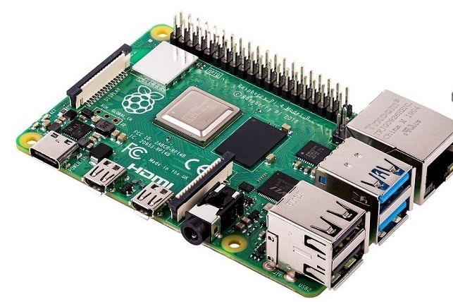
the goal of understanding one aspect of the system [2]. For example, a Computer-Aided
Design (CAD) model of a car may store information about the sizes of the wheels,
shapes of the chassis, styles of the car, and so on, but it does not contain information
about how the forces acting on the car affect its movement. An engineer who desires
to analyse the dynamics of the car may build a dynamic model described by the differ-
ential equations introduced in, e.g., [3, Section 5].
    Beyond better understanding, models can assist with optimising the overall system,
discovering causes and effects, measuring consequences of changes, and communicat-
ing among engineers. Once the system is deployed, the models used to build it should
not be discarded. Instead, they should be integrated into a Digital Twin (DT).
    DT is often defined as a framework that integrates modelling, simulation, moni-
toring, and optimisation technologies, with the intent of adding value to the use of the
Physical Twin (PT) [4,5]. For instance, a DT provides the ability to run simulations that
reproduce and predict the behaviour of the PT under its current operating conditions.
The following important parts are highlighted [6]:
Data – collected from the PT through sensors over time;
Models – knowledge about different aspects of both the cyber and the physics of the
       PT and its environment1 ; and
Algorithms – techniques that use data and models, manipulating those to generate
       more data and knowledge (e.g., fault detectors, supervisory controllers, state es-
       timators, optimisers).
    An example common structure of a DT is represented in fig. 1. In fig. 1, the DT
employs calibration algorithms to update the models of the CPS and environment with
the best estimate of the parameters. The resulting data is then used to inform monitors
that check whether the system is performing safely and optimally. When violations are
detected, humans (or other algorithms) may decide to make changes to the physical
twin.
    DTs increase the value of their physical counterparts by potentially enabling ad-
vanced visualisations, reconfigurability (and therefore robustness with respect to chang-
ing environment), safety, predictability, and reduced maintenance.
    The often vague definitions and claims about DTs makes the concept hard to distin-
guish from: self-adaptive systems [7, 8], autonomic computing [9], Industry 4.0 [10],
models@runtime [11, 12], and supervisory controllers [13].
    We introduce the Incubator case study as an attempt to clearly identify the tech-
niques used in digital twinning. This system is a simple, yet representative, CPS and
PT. Detailing how the DT is built is out of the scope of this manuscript, but we sketch
how such implementation can be done, and which technologies can be used. This
makes it easier for the reader to see the similarities of DT to the aforementioned re-
lated research areas.
    The publicly available repository2 contains the up-to-date hardware and software
specifications of the case study.
    The rest of the report is organized as follows: section 2 introduces the incubator
   1 It is worth noting that models can be described at different levels of abstraction, and typically there is a

tendency that accurate models also are very slow to analyse for example by means of simulation.
   2 https://github.com/INTO-CPS-Association/example-incubator

                                                       2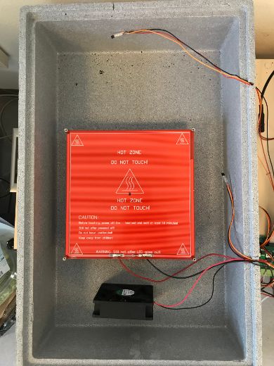
Figure 1: Schematic overview of a CPS-based Digital Twins. The letter “C” and “P”
represents “Cyber” and “Physical” respectively.

system, including the hardware and software setup. Then we built two models with
calibration method in section 3. section 4 shows two kinds of experimental results.
Afterwards section 5 sketches the goals of the digital twinning and future work. Finally,
we summarise the report in section 6.

2     Incubator Case Study
The main goal of the incubator is to reach a certain temperature within a box and
regulate it regardless of the content inside. The physical components in the incubator
form a plant that is controlled by a Raspberry Pi. The overall systematic diagram of
the Incubator is shown in fig. 2.

2.1    Hardware Setup
We start with a brief description of the hardware components, back-of-the-envelope
calculations, and refer the reader to the online repository3 for more details.
    The plant of the Incubator consists of (see fig. 3):
    • A styrofoam box in order to have an insulated container.
    • A heatbed to heat up the content inside the styrofoam box.
    • A fan to distribute the heating inside the box.
    • Two temperature sensors to monitor the temperature inside the box.
    • One temperature sensor to monitor the temperature outside the box.
    3 https://github.com/INTO-CPS-Association/example-incubator

                                           3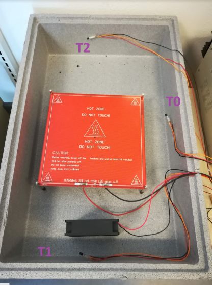
Insulated
                                 Container

                                     Temperature
               Heatbed
                                       Sensors                       Temperature
                           Fan                                         Sensor

                                                   Content

                                 Controller

                    Figure 2: Schematic overview of the Incubator.

    • A controller to communicate with the DT, actuate the heatbed, the fan, and read
      the temperature sensors.
    • A Printed Circuit Board (PCB) connecting all electrical components.
    • A power supply.

2.1.1   The Insulated Container
The aim of the insulated container (see fig. 3(a)) is to preserve the energy generated by
the heatbed inside the box as much as possible, so as to minimise the potential impact
of the environment around the CPS. We chose the styrofoam box (see fig. 3(a)) made
of polystyrene for its good insulation properties.
    The air volume inside the box is about 0.03m3 . This value will be used for estima-
tion of energy and air flow requirements.

2.1.2   The Heatbed
The heated content in the incubator is the air inside the box. The heatbed was used (see
fig. 3(b)) as the surface heat source instead of a bar-like or point-like heat source. This
is because we want to make the heat energy distributed as uniformly as possible.
     Assuming that
     • there is no heat transfer into the box walls,
     • the mass of the air inside the box is 0.04kg,
     • the air heat capacity is 700J kg−1 K−1 and it does not change due to the temper-
       atures, pressure and so on,
the heatbed can warm up the air inside the box from 293K (20°C) to 300K (about
26.85°C), by producing

                 0.04kg ∗ (300K − 293K) ∗ 700J kg−1 K−1 = 200J

                                              4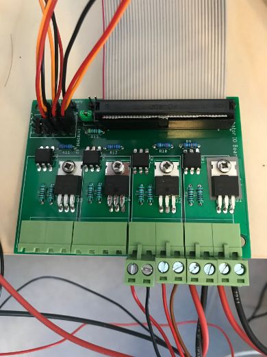
(a) The styrofoam Box is used as an       (b) The heatbed is approximately
              insulated container.                      214 ∗ 214 ∗ 3 mm to fit the styrofoam
                                                        box.

        (c) The Fan, used to circu-     (d) Raspberry Pi 4 Model         (e) Temperature Sensor
        late the air in the styrofoam   B
        box. It can be run on 12V
        or 24V.

                             Figure 3: Components used in the incubator

of energy.
    Assuming it delivers at least 100W = 100J s−1 of power, 200J be provided in
under 2 seconds. As we will show later, this is more than enough power.

2.1.3      The Fan
We installed a fan (see fig. 3(c)) inside the box to circulate the air inside the box for
making the temperature as uniformly distributed as possible. The fan airflow is about
0.02m3 s−1 .
   With a box volume of 0.03m3 , the fan should take 2 seconds to move all the air
within the box.

2.1.4      The Raspberry Pi
A Raspberry Pi 4 Model B (see fig. 3(d)) was selected to implement the controller. The
General Purpose Input/Output (GPIO) connectors on the Raspberry Pi can be used to
connect many accessories such as temperature sensors, fan, and the heatbed. Further-
more it supports wireless internet out of the box, with built-in Wi-Fi and Bluetooth,

                                                    5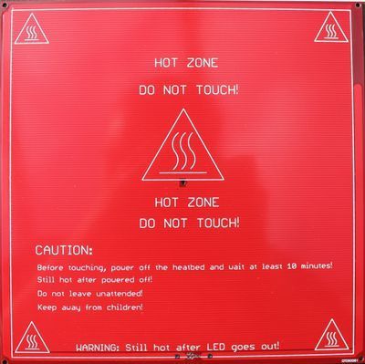
which simplifies deployment of the controller.
2.1.5 The Temperature Sensor
It is necessary to get feedback from the temperature sensors for feedback control. To do
this, a DS18S20 High-Precision 1-Wire Digital Thermometer (see fig. 3(e)) was used
for measuring the temperature. This temperature sensor can measure temperatures
from -55 °C to +125 °C with an accuracy of 0.5 °C from -10 to +85 °C, which is
suitable for the physical incubator. And each DS18S20 has a unique 64-bit serial code,
which allows multiple DS18S20s to function on the same 1-Wire bus. Such 1-wire bus
support to connect multiple sensors with only one GPIO. In the incubator system, three
sensors were deployed for detecting the temperature.
2.1.6 The PCB Design
Controlling the heatbed requires approximately 4A current which is not supported by
the Raspberry Pi. Instead, MOSFETs are used to separate the control signals from the
Raspberry Pi and the driving currents. In order to decouple the control signals from the
Raspberry Pi to the MOSFETs, we use optocouplers. The PCB schematic is shown in
fig. 4.
SUPPLY1
PWM0
PWMOUT1
X2-4
VCC3.3
3.3v
JP8
1
2
X2-2
PWM0
X2-3
OK1
5v R9 X2-1
10k
1 6
R5
2 5 Q1
JP10 220
1 IRLZ44N GND1
1 2 2 4
VCC3.3 VCC5V
3 4 JP9 SUPPLY2
5 6 GND TIL111
PWMOUT2
VCC5V
10k
7 8
R1
1-WIRE PWM1
9 10
X3-4
11 12
GPIO17
13 14
GPIO27 X3-2
15 16
PWM1
17 18
X3-3
19 20
21 22 OK2
R10 X3-1 GND2
10k
23 24 1 6
R6
25 26 5 Q2
220
27 28 IRLZ44N
29 30 2 4
31 32
PWM0
PWM1 33 34 GND TIL111
10k
35 36
R2
37 38
39 40 GPIO5
GND X4-4
SUPPLY3
PI Connector X4-2
GPIO17
OUT3
X4-3
OK3
R11 X4-1
10k
1 6
R7
5 Q3
220 GND3
IRLZ44N
2 4
GND TIL111
10k
R3
1Wire Supply
1W Supply
GPIO27
2 GPIO6
1
SUPPLY4 X5-4
VCC3.3
JP6
1
2
3
OUT4
JP7 X5-2
OK4 X5-3
R12
1-WIRE
10k
1 6
R8
1WIRE_VCC
5 Q4 X5-1 GND4
JP5 JP4 JP3 JP2 JP1 220
R13 IRLZ44N
1 1 1 1 1 2 4
2 2 2 2 2
4.7k 3 3 3 3 3 GND TIL111
10k
R4
Temp5 Temp4 Temp3 Temp2 Temp1
GND
Figure 4: PCB schematics.
6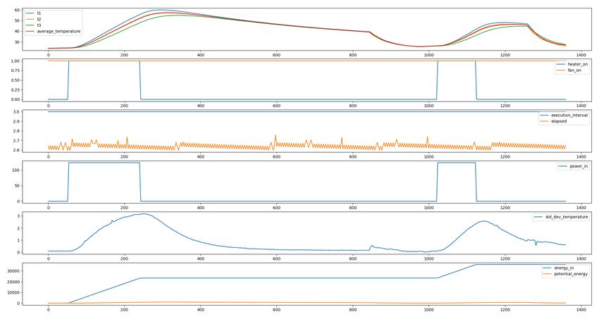
2.1.7   The Connections
The configuration details are shown in fig. 5.

                               4cm              12cm

                    11.5cm
                                                                  Temperature
                                                                    Sensor 2
                                                                             Temperature
                                                           Temperature        Sensor 1
                                                            Sensor 3
                                         23cm

            3.5cm

                                                7cm

            3.5cm

                13cm
                                                                                       Fan   To 18V          To
                                                                                             Power Heatbed power
                                                                                             Supply        supply
                     8.5cm
                             4.5cm
                                                16cm

           (a) Styrofoam box configuration.                            (b) PCB board connection.

                                 Figure 5: Connections of components.

2.2     The Incubator Software Setup
The software setup includes a controller, a low-level driver, and a communication
server for delivering data. Fig. 6 shows the schematic of the software system.
Communication Server – We used a Rabbit MQ server, running on the raspberry pi
      itself.
Low-level driver – Abstracts the low level communication with the sensors and actu-
      ators.
Controller – Implements the control logic required to regulate the temperature inside
      the incubator. It receives the measured data and sends commands through the
      communication server.

2.2.1   The Communication Server
For the case study, the RabbitMQ4 server was deployed for synchronisation and com-
munication. With tens of thousands of users, RabbitMQ is one of the most popular
open source message brokers. RabbitMQ is a mature, lightweight, and easy to deploy
on premises and in the cloud.
  4 https://www.rabbitmq.com/

                                                       7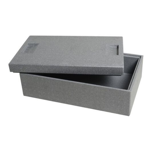
Physical Twin

                                                    Rabbit MQ server

                          Raspberry Pi

                                     Controller                   low_level_driver
                                (Python Application)            (Python Application)

                                              GPIO

                                         Temperature sensors, fan, heater

         Figure 6: Schematic of the software deployment of the components.

    The controller on the Raspberry Pi is listening from the RabbitMQ server for com-
mands of controlling the fan and the heatbed and at the same time sharing the control
states to the RabbitMQ server.
    We choose RabbitMQ because it greatly facilitates the digital twinning process, as
the DT can be implemented by components that listen to the messages being passed
between the controller and the load level driver, as illustrated in fig. 7.

2.2.2   The Low-Level Driver
The low-level driver is used to interact with the PT and to issue the states of the PT
to the RabbitMQ server. In order keep the device in a safe state, a safe protocol is
incorporated into the low-level driver.
    The low level driver periodically reads the temperature data, and checks if there are
commands from the controller, through the communication server. The temperature
data is uploaded to the communication server.

2.2.3   The Controller
The controller used in the case study is a comparable to a bang-bang controller, which
a small difference described below. The control strategy is executed after receiving the
temperature measurements.
    The principle of bang-bang control is that when a reference temperature is given
to the controller, the controller issues a heating signal turning on the heatbed until the
measured temperature from sensors reaches the reference temperature. Because of the
delayed effect of the temperature, the controller needs to wait after each actuation, to
make sure the temperature does not rise too much. Figure 8 shows the state chart of the
controller. The controller parameters are:

                                                         8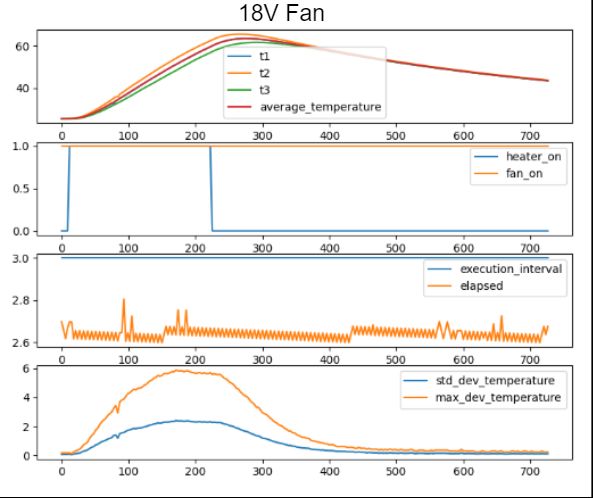
Physical Twin       Digital Twin

                     Issue Commands                       Receive Messages
        Controller                      RabbitMQ                                                                       Digital Twin

                     Issue Commands                      Issue Commands
          Fan                         Low_Level_Driver                         Heated Bed

                                                Communicate Data

                                      Temperature
                                        Sensors

Figure 7: Overview of communication in the Incubator. The arrows represent the in-
formation flow.

LL – Lower limit for temperature;
UL – Upper limit for temperature;
H – Heating duration;
C – Waiting duration.

                                                         If T < LL, turn heater on.

                                            cooling                                       heating
                                             down

                                                                             after C s,
                                               after C s,                     if T< UL
                                               if T > UL
                                                                                            after H s

                                                                 waiting
                                                                heater off

                                      Figure 8: Controller Statechart.

3    Modelling the Physical Twin
The dynamics model we created mainly focuses on predicting the temperature inside
the styrofoam box. To simplify the model, a few assumptions were made.

                                                                   9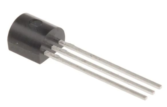
Assumption 1 The temperature inside the box is distributed uniformly. This was ac-
complished by deploying a fan inside the box ensuring distribution of the air inside the
box. We test this assumption in section 4.

Assumption 2 The box walls do not accumulate heat, or such heat accumulation has
little effect on the air temperature inside the box.

Assumption 3 The specific heat capacity of the air inside the box is assumed constant,
even when pressure and humidity may change.

Assumption 4 The majority of electrical power is transferred to heat energy, which
means the heatbed inside the box does not absorb the heat energy and the heat energy
generated by the fan was ignored as well.
   Two different models were built:
Model A: relies on all assumptions.
Model B: relies on all assumptions except Assumption 4.
    To obtain the dynamic models of the temperature, the model was developed by
considering the way the energy flows. If the amount of the energy used for heating the
air is acquired, then this energy can be converted into the temperature inside the box
by calculating a basic heat equation:

                                      Q = cm∆T,                                      (1)

where Q represents the energy transferred, m equals the mass of the heated object, c is
the specific heat capacity which is dependent on many factors such as temperature and
pressure, in this project to simplify the dynamic model, c is considered to be constant,
and not dependent of temperature and pressure following Assumption 3. ∆T is the
temperature change either in Kelvin or in °C. All the units are SI-units. Based on this
equation, the energy can be converted into temperature, which is the basis of the two
time-dependent models.
    We now explain the derivation of Model A, and Model B is described in section 3.2.

3.1   Model A
In model A, only the transformation of the energy between the air inside the box and
outside of the box is considered. This means all the energy from the power supply
is transferred to the air inside the box (recall Assumption 4 above). The total energy
brought in by the power supply is:

                                  Epower in = V I∆t,                                 (2)

where V and I are the voltage and current provided by the power supply and ∆t is the
time interval.
    Since the temperature of the air inside the box differs from that of the box, part of
the energy flows from the air inside the box to the box. A parameter Gbox (unit: J K−1 )

                                           10
was used to link the difference between the room temperature and the air temperature
inside the box with the energy flowing to the box, which is:
Epower out = Gbox (Tbair − Troom ), (3)
where Tbair represents the temperature of the air inside the box and Troom is the room
temperature.
By subtract eq. (3) from eq. (2), we can get the difference of the energy. Substitute
the difference of the energy to the Q in eq. (1), a new equation is obtained:
dTbair 1
= [V I∆t − Gbox (Tbair − Troom )]. (4)
dt cbair mbair
Since cbair , the capacity of the air inside the box, is assumed to be constant but un-
known and mbair , the mass of the air inside the box, is a constant, a new parameter
Cair (unit:J K−1 ) is used to replace cbair ∗ mbair . A more compact equation with
model A is:
dTbair 1
= [V I∆t − Gbox (Tbair − Troom )]. (5)
dt Cair
3.2 Model B
The main difference between Model B and Model A is that Model B relaxes Assump-
tion 4. In other words, it considers the heatbed to also accumulate heat.
Similar to Gbox , Gheater (unit:J K−1 ) is used to describe the energy transferred
from the heatbed to the air. The heat bed has its own specific heat capacity and mass.
The energy transferred from the heatbed to the air is:
Eheater2air = Gheater (Theater − Tbair ). (6)
And the energy retained in the heatbed is:
Eheater = V I∆t − Eheater2air . (7)
This energy makes the temperature of the heatbed increase.
The process of energy flowing from the air to the box is the same as model A. The
energy used for heating the air can be calculated by:
Eair = Gheater (Theater − Tbair ) − Gbox (Tbair − Troom ). (8)
Both the energy Eheater and Eair are used for heating the heatbed and the air. Accord-
ing to eq. (1), the changes in the temperature of the heatbed and the air are:
dTheater 1
= (V I∆t − Gheater (Theater − Tbair ))
dt Cheater
(9)
dTbair 1
= [Gheater (Theater − Tbair ) − Gbox (Tbair − Troom )].
dt Cair
The model (eq. (9)) considered more detailed than Model A, has four parameters
Cheater , Cair (unit:J K−1 ), Gheater , and Gbox (unit:J K−1 ).
113.3 Calibration
Although the dynamics models have been built, they contain free parameters. In order
to utilise the models, the models need to be calibrated for the incubator. The results of
the calibration are detailed in section 4.2, and here we detail the procedure.
A non-linear least squares solver was used to calibrate the parameters of the models
derived above. Then the models are evaluated using the estimated parameters. After-
wards the resulting behaviour is compared with a data trajectory that is obtained by
running an experiment of the incubator. Finally using an optimisation function inside
the python Scipy package [14] to obtain the values of the parameters. Such a function
finds the parameters that minimizes the residual error. When the residual error is small
enough, the optimised parameters can be obtained.
The principle of the package is based on least-square, it assumes that:
y = f (x, θ) + (10)
where f (x, θ) is the model needed to be calibrated, θ are the parameters represented in
a vector in the model, and y is the label or the measured data.
A cost function or an objective function can be provided as:
X
J= (yi − f (xi , θ))2 (11)
The objective is to acquire a minimal value of J, and at the same time, the correspond-
ing θ are the value needed. In order to minimise the cost function, the most commonly
used one is gradient descent. After multiple iterations, the value of the cost function
goes to a sufficient small value and the θ are obtained simultaneously.
4 Experimental Results
Two kinds of experiments have been conducted. One is for testing Assumption 1.
Another has been conducted to calibrate the parameters of the models. The source
code used for the experiments is available online5 .
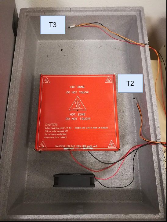
4.1 Uniform Temperature Experiments
The temperature inside the box is assumed to be distributed uniformly, thanks to the
fan. An experiment was conducted to test the uniformity of the temperature. In this
case, it is not necessary to know the temperature of the room, so the sensor measuring
the room temperature was used to test the air temperature inside the box. The setup
with the sensors can be seen in fig. 9.
During the experiment, the fan is always turned on in order to circulate the air inside
the box and the fan blows the wind from the bottom to the top in fig. 9. The heatbed
was turned on during two periods. The experimental results are shown in fig. 10.
5 https://github.com/INTO-CPS-Association/example-incubator
1211.5cm T3
23cm
T1
11.5cm
T2
Figure 9: Three sensors are placed in different places.
Box opened
Box opened
Highest
disagreement
Highest
disagreement
Figure 10: Experimental results of a uniform temperature inside the box. The first sub-
figure shows the temperatures measured from the three sensors change over time. The
temperature measured from the sensor T2 is overlapped by the average temperature,
which is hard to read. The other subfigures show different information regarding the
experiment such as the status of the heatbed, the power introduced in the system, etc.
From the first subfigure in fig. 10, it seems that the temperature correlates with the
distance to the heatbed and the average temperature matches the temperature measured
13from T2 in fig. 9.
Since only three temperature sensors are included in the box and one is necessary
for measuring the room temperature, sensor T2 in fig. 9 was rearranged to the new
place in fig. 11 and sensor T1 in fig. 9 was taken to be outside of the box measuring the
room temperature. The new setup of the sensors is shown in fig. 11. One was placed
in the hottest position which is T2 position in fig. 11 and another one was placed in the
coldest position, T3 position in fig. 11. Taking the average of those two, the average
temperature of the air inside the box is acquired.
Figure 11: Optimized setup for sensors. The position of T2 and T3 are the same with
fig. 9
In order to determine whether a stronger wind flow contributes a more uniform
temperature, one additional experiment was conducted based on the setup in fig. 9. All
the conditions were the same except the voltage of the fan which is 18V while in the
previous experiment it was 12V . The result is shown in fig. 12.
The previous setup in fig. 10 showed a discrepancy of a maximum of 7 °C between
the three temperature measurements while the maximum discrepancy in a new setup
with 18 voltage on the fan is 6 °C.
14Figure 12: The experimental result with 18 voltage on the fan.
4.2 Calibration Experiment
Based on the optimised setup for sensors (fig. 11), a calibration experiment was con-
ducted and the calibration method has been described in section 3.3. The experiment
was used for generating a data trajectory. The calibrated parameters for the model A
are Cair (unit : J K−1 ) = 616.56 and Gbox (unit : J K−1 ) = 0.65. And the cali-
brated parameters for the model B are Cair (unit : J K−1 ) = 486.12, Gbox (unit :
J K−1 ) = 0.856, Cheater (unit : J K−1 ) = 33.65, and Gheater (unit : J K−1 ) = 0.87.
The calibration result can be seen from fig. 13. Model A is sufficient to get a rough
Purple line is the
average room
temperature.
Blue is Model A
Orange is Model B
Red is the
heatbed signal
Figure 13: The calibration result.
approximation of the system magnitude and time scale, whereas the model B is better
at predicting the inertia of the heatbed itself.
155 Digital Twinning Goals
In this section, we sketch the goals of the digital twinning process for the incubator
case study. This constitutes our future work.
Our goal is to implement a DT framework that enables
Real-time visualization of the incubator status – achieved by listening to the con-
troller and low level driver messages, and relaying that data into a time series
database, and plot the data into a dashboard.
On demand calibration – achieved by automatically running the calibration process
described in section 3.3. This is similar to the tracking simulator implemented
in [15].
Anomaly detection and Heatbed state estimation – This is achieved by running a
Kalman filter [16] that uses Model B developed in section 3 and correlates the
measure data to the (non-measured) heatbed temperature.
What-if simulations – This is implemented by running co-simulations that relay the
historical or real-time data from the PT (e.g., similar to what is done in [17]). It
can be used to, e.g., optimize the controller parameters introduced in fig. 8.
Self-adaptation loop – This is the functionality that truly closes the loop of the DT.
We envision that, whenever a new object (imagine a bucket of cold water) is
placed in the incubator, the DT will:
1. detect that the plant behavior has changed (given by the anomalies detected
by the Kalman filter);
2. schedule an experiment to gather relevant data (e.g., let the plant cool down
to a safe temperature, then ramp up heating for some time).
3. configure the controller for the new experiment;
4. gather the experiment data;
5. run the calibration of Model B for new experiment;
6. re-configure Kalman filter with new parameters;
7. run what-if simulations to optimize the controller behavior; and
8. finally re-configure the controller.
6 Summary
We described the implementation and modelling of the incubator case study. Hardware,
software, and datasets are available online6 . Using this example to set the terminology,
we proceeded to demystify the DT concept and its goals.
6 https://github.com/INTO-CPS-Association/example-incubator
16References
[1] Edward A. Lee. Cyber Physical Systems: Design Challenges. In 11th IEEE
International Symposium on Object Oriented Real-Time Distributed Computing
(ISORC), pages 363–369, 2008.
[2] Thomas Kühne. What is a Model? In Language Engineering for Model-
Driven Software Development, volume 04101. Internationales Begegnungs- und
Forschungszentrum für Informatik (IBFI), 2005.
[3] Dieter Schramm, Manfred Hiller, and Roberto Bardini. Vehicle Dynamics.
Springer, 2014.
[4] Fei Tao, He Zhang, Ang Liu, and A. Y. C. Nee. Digital Twin in Industry: State-
of-the-Art. IEEE Transactions on Industrial Informatics, 15(4):2405–2415, April
2019.
[5] Aidan Fuller, Zhong Fan, Charles Day, and Chris Barlow. Digital Twin: Enabling
Technologies, Challenges and Open Research. IEEE Access, 8:108952–108971,
2020.
[6] Louise Wright and Stuart Davidson. How to tell the difference between a model
and a digital twin. Advanced Modeling and Simulation in Engineering Sciences,
7(1):13, December 2020.
[7] Danny Weyns, M. Usman Iftikhar, Didac Gil de la Iglesia, and Tanvir Ahmad. A
survey of formal methods in self-adaptive systems. In Proceedings of the Fifth
International C* Conference on Computer Science and Software Engineering -
C3S2E ’12, pages 67–79, Montreal, Quebec, Canada, 2012. ACM Press.
[8] Tao Chen, Rami Bahsoon, and Xin Yao. A Survey and Taxonomy of Self-
Aware and Self-Adaptive Cloud Autoscaling Systems. ACM Computing Surveys,
51(3):1–40, June 2018.
[9] J.O. Kephart and D.M. Chess. The vision of autonomic computing. Computer,
36(1):41–50, January 2003.
[10] Heiner Lasi, Peter Fettke, Hans-Georg Kemper, Thomas Feld, and Michael Hoff-
mann. Industry 4.0. Business & information systems engineering, 6(4):239–242,
2014.
[11] Nelly Bencomo, Robert France, Betty H. C. Cheng, and Uwe Aßmann, editors.
Models@run.Time, volume 8378 of Lecture Notes in Computer Science. Springer
International Publishing, Cham, 2014.
[12] Nelly Bencomo, Sebastian Götz, and Hui Song. Models@run.time: A guided
tour of the state of the art and research challenges. Software & Systems Modeling,
18(5):3049–3082, October 2019.
17[13] Mohammad Karimadini, Ali Karimoddini, and Abdollah Homaifar. A Survey on
Fault-Tolerant Supervisory Control. In 2018 IEEE 61st International Midwest
Symposium on Circuits and Systems (MWSCAS), pages 733–738, Windsor, ON,
Canada, August 2018. IEEE.
[14] SciPy 1.0 Contributors, Pauli Virtanen, Ralf Gommers, Travis E. Oliphant, Matt
Haberland, Tyler Reddy, David Cournapeau, Evgeni Burovski, Pearu Peterson,
Warren Weckesser, Jonathan Bright, Stéfan J. van der Walt, Matthew Brett,
Joshua Wilson, K. Jarrod Millman, Nikolay Mayorov, Andrew R. J. Nelson, Eric
Jones, Robert Kern, Eric Larson, C J Carey, İlhan Polat, Yu Feng, Eric W. Moore,
Jake VanderPlas, Denis Laxalde, Josef Perktold, Robert Cimrman, Ian Henrik-
sen, E. A. Quintero, Charles R. Harris, Anne M. Archibald, Antônio H. Ribeiro,
Fabian Pedregosa, and Paul van Mulbregt. SciPy 1.0: Fundamental algorithms
for scientific computing in Python. Nature Methods, 17(3):261–272, March 2020.
[15] Christian Møldrup Legaard, Cláudio Gomes, Peter Gorm Larsen, and Frederik F.
Foldager. Rapid Prototyping of Self-Adaptive-Systems using Python Functional
Mockup Units. In 2020 Summer Simulation Conference, SummerSim ’20, page
to appear, Virtual event, 2020. ACM New York, NY, USA.
[16] Rudolph Emil Kalman. A New Approach to Linear Filtering and Prediction Prob-
lems. Journal of Basic Engineering, 82(1):35, March 1960.
[17] Casper Thule, Cláudio Gomes, and Kenneth Lausdahl. Formally Verified FMI
Enabled Data Broker: RabbitMQ FMU. In 2020 Summer Simulation Conference,
SummerSim ’20, page to appear, Virtual event, 2020. ACM New York, NY, USA.
18You can also read