The REHVA European HVAC Journal
←
→
Page content transcription
If your browser does not render page correctly, please read the page content below

The REHVA
 European HVAC Journal
 Volume: 55 Issue: 2 A p r i l 2 018 w w w.rehva.eu

EN 16798-3: Ventilation for Non-residential Buildings
 New Concept of Natural Air Conditioning
 History of Indoor Environment

 Interviews with
 Hannu Saastamoinen,
 CEO of Swegon and
 Jyri Luomakoski,
 CEO of Uponor

Eurovent
 Certita
 Certification
 YOU DON’T WANT TO LIVE IN A WORLD
 WITHOUT THIRD-PARTY CERTIFICATION.

ENJOY PEACE OF MIND AND CHOOSE PRODUCTS SIMPLY AND SECURELY
We promise you TRANSPARENCY, INTEGRITY, INDEPENDENCE,
IMPARTIALITY. Our robust certification process includes : continuous
verification, product sampling, independent tests conducted by
accredited laboratories and agencies, selection software checks and
independent assessment.

Since 1994 EUROVENT CERTITA CERTIFICATION certifies the
 Download your customized certified solution on :
performance ratings of HVAC-R products for residential home and
industrial facilities. www.eurovent-certification.com
Getty Images ©sturti
The REHVA www.rehva.eu
 Contents
European HVAC Journal Download the articles from www.rehva.eu -> REHVA Journal
Volume: 55 Issue: 2 April 2018

Editor-in-Chief: Jaap Hogeling
 EDITORIAL 58 Active Room-Human Feedback System:
jh@rehva.eu
 Design and Discussion
Associate Editor: Stefano Corgnati, Italy
 5 The Revised EPBD – A step forward S. Hossein Sagheby
stefano.corgnati@polito.it
 Jaap Hogeling

Editorial Assistant: Chiara Girardi, INTERVIEWS
cg@rehva.eu ARTICLES
 62 Interview with Mr. Hannu
General Executive: Ismail Ceyhan, Turkey 6 CEN Standard EN 16798-3:2017 Saastamoinen, Chief Executive Officer
 on ventilation for non-residential of Swegon AB
 buildings: Performance requirements
REHVA BOARD Livio Mazzarella & Jaap Hogeling 65 Interview with Mr. Jyri Luomakoski,
President: Stefano Corgnati Chief Executive Officer of Uponor
 14 On the history of indoor environment Corporation
Vice Presidents: and it’s relation to health and
Atze Boerstra wellbeing
Frank Hovorka Lada Hensen Centnerová EU POLICY NEWS
Jarek Kurnitski
Milos Lain 21 Natural air conditioning: what are we 70 The 2nd recast of the Energy Performance
Catalin Lungu waiting for? of Buildings Directive (EPBD)
Manuel Carlos Gameiro da Silva Ben Bronsema, Ronald van Luijk, Peter Swier ,
 Jaap Veerman & Joost Vermeer
EDITORIAL BOARD - 2018
 NEWS
 26 Guidance for standard evaluation
Francis Allard, France
 procedures of indoor environmental 73 ISH China & CIHE 2018 announces its
Ahmet Arisoy, Turkey largest ever exhibition space catering
 parameters in schools
Marianna Brodatch, Russia to strong demand from exhibitors
 Thomas Hartmann, Christine Knaus & Martin H.
Vincenc Butala, Slovenia
 Spitzner 74 Re-thinking Organizational Savings
Stefano P. Corgnati, Italy
Francesca R. d’Ambrosio, Italy 34 Modern developments of high- through HVAC
Ioan Silviu Dobosi, Romania performance industrial fans
Andy Ford, United Kingdom Karadzhi Sergey, Brodach Marianna & Karadzhi
Jaap Hogeling, the Netherlands REHVA WORLD
 Viacheslav
Karel Kabele, Czech Republic 76 REHVA at MCE 2018
Jarek Kurnitski, Estonia 39 The KUEHA project
Livio Mazzarella, Italy - A new solution for space cooling 78 REHVA at ACREX 2018
Renato Merati, Italy during summer
Birgit Müller, Germany Markus Arendt, Ralf Gritzki, Lars Haupt, André 82 REHVA-ISHRAE statement on
Natasa Nord, Norway Kremonke, Alf Perschk & Clemens Felsmann Indoor Environmental Quality and
Branimir Pavkovic, Croatia Energy Performance of Schools
Dusan Petras, Slovakia
 45 Project of HVAC systems for the
 meteorological station 83 Clima 2019
Olli Seppänen, Finland
Branislav Todorovic, Serbia Dagmara Ćwiek, Tomasz Kolsicki, Karolina Kowal &
Peter Wouters, Belgium Bartłomiej Tokarzewski PRODUCT NEWS
 52 Evaluation of the Performance of 85 Prevent poor air quality indoors!
 Phase Change Materials in relation Or what kind of air are you inhaling?
ADVERTISEMENTS to Balanced Distribution of Heating
Ms Chiara Girardi, cg@rehva.eu Energy Cost in Residential Buildings
 Eda Köse & Gülten Manioğlu 91 EVENTS
SUBSCRIPTIONS and
CHANGES OF ADDRESSES
REHVA OFFICE:
Washington Street 40 Advertisers
1050 Brussels, Belgium
Tel: +32-2-5141171 99 Eurovent Certita Certification...... 2 99 Belimo........................................ 84
info@rehva.eu, www.rehva.eu 99 2nd Buildings India 2018.............. 4 99 REHVA Supporters.................... 88
 99 Lindab........................................ 13 99 REHVA Members...................... 89
PUBLISHER 99 Vaisala........................................ 46 99 REHVA Guidebooks.................. 92
TEKNİK SEKTÖR YAYINCILIĞI A.Ş.
 99 Uponor....................................... 69
Barbaros Mahallesi, Uğur Sk. No: 2/2
Üsküdar/İstanbul, Turkey

REHVA Journal is distributed in over 50 countries through the
Member Associations and other institutions. The views expressed
 Next issue of REHVA Journal
in the Journal are not necessarily those of REHVA or its members.
 Instructions for authors are available at www.rehva.eu
REHVA will not be under any liability whatsoever in respect of
 (> Publications & Resources > Journal Information)
contributed articles.
 Send the manuscripts of articles for the journal
Cover background photo by to Jaap Hogeling jh@rehva.eu

EV&BATTERY
TECH INDIA SUMMIT
 2 nd S LAR

 Buildings
 India 2018
Editorial

The Revised EPBD
– A STEP FORWARD
Long debates finally resulted in a revised version to be adapted in April 2018 by the European
Parliament (see also article on page 70). The renewed EPBD will push EU Member States to
increase their efforts to reduce the energy use and CO2 emission in the built environment.

I
 t is up to us as professionals in the HVAC&R and group of overarching EPB standards (Member States
 building design community to design, retrofit and shall describe their national calculation methodology
 install more energy efficient and smart buildings following the national annexes of the overarching
and building systems. The cost-efficiency of the solu- standards (EN- ISO 52000-1, 52003-1, 52010-1,
tions to meet the national energy performance require- 52016-1, and 52018-1). This is a first step to more
ments will also be influenced by the choices made by overall transparency in Europe. In addition to what is
the national building regulating authorities. Such as already included in these overarching EPB standards,
their choices and assumptions assessing the Primary more clarity on the assessment background of PEF’s and
Energy Factors (PEF’s) and CO2 emission factors of CO2 emission factors for various systems and energy
the various energy sources. This is one of the reasons sources is needed. CEN/TC371-WG1 currently works
why the Annex 1 of the EPBD requires EU-MS’s to on an additional EPB standard “Determination and
report and motivate their choices according the EN reporting of Primary Energy Factors (PEF) and CO2
ISO 52000-1 and several other of the overarching EPB emission factors”. This standard will provide a uniform
standards. These national choices will influence the procedure to describe how the (national) Primary
role of bio-fuels, district-heating and cooling systems, Energy Factors and CO2 emission factors related to
CGHP and HP systems. How PV and Wind-energy energy delivered to or exported from buildings have
is awarded in relation to the Energy Performance been assessed: the elements that are or are not taken into
declarations of buildings (the Energy Certificate and account and related assumptions. It is expected that this
related regulation on the requirement levels) is also standard will lead to more transparency throughout
an important issue. Are these sustainable sources just Europe and an increased understanding of the impact
rewarded as the sustainable part of the national energy of the choices. This will help both policy makers and
grid or can they be considered as integral part in the the designers and retrofitters of our buildings and their
building system and, if so, under which conditions and systems and connected energy grids to make the correct
circumstances (e.g. to optimize implementation and choices towards an effective reduction of the energy use
allocation of renewable resources and to avoid double and CO2 emission of buildings in Europe.
counting)? These choices have an impact on a cost-
efficient equilibrium between decarbonised energy
supply and reducing the final energy use of buildings to
achieve the 2030, 2040 and long-term 2050 objectives.

The revised EPBD doesn’t always give clear answers
or guidance. But it is clear that related concepts like
energy storage capability and to be developed Smart
Readiness Indicators will become more relevant. This
may help to develop transparency regarding the inter-
action between energy grids and built environment.
Annex 1 of the EPBD requires EU-MS’s to declare JAAP HOGELING
their national EP assessment procedures on basis of a Editor-in-Chief

 REHVA Journal – April 2018 5

Articles

 CEN Standard EN 16798-3:2017 on
 ventilation for non-residential buildings:
 PERFORMANCE REQUIREMENTS
 LIVIO MAZZARELLA status of a national standard at the latest by February
 Prof of Building Physics and 2018.1
 HVAC Systems Full Professor
 at Politecnico di Milano This European Standard is part of a series of standards
 – Department of Energy – aiming at international harmonization of the meth-
 Milan – Italy odology for the assessment of the energy performance
 AiCARR Vice president – of buildings under a mandate given to CEN by the
 REHVA Fellow European Commission, called ‘recast EPBD’ standards
 livio.mazzarella@polimi.it or just EPB standards. These standards have a new
 common format: two documents for each standard-
 ized item, a true standard EN xxxx and a supporting
 technical report CEN/TR xxxx. The former reports a
 set of normative rules, while, the latter explains how to
 apply the related EN standard and gives informative
 additional rules and data. Because the EPB standards
 have been produced with the aim of supporting the
 recast EPBD and its application at national level, a
 JAAP HOGELING certain degree of freedom in their application was a
 EPB Center, mandatory request. Thus, these standards provide a
 Jaap.hogeling@epb.center certain flexibility regarding the methods, the required

 Introduction 1 Meanwhile CENTC156WG20 works on an update of this standard. This to
 optimise the convergence with other EPB standard and the future TS’s
 August 2017, CEN published the new standard
 regarding natural and hybrid ventilation systems (see article in RJ 2018-01).
 EN 16798-3:2017 “Energy performance of build- This update may also include a better aligning with the filter standards and ErP
 ings - Ventilation for buildings – Part 3: For non- standards on ventilators.
 residential buildings – Performance requirements for The purpose of this revision is to consider further developments in the
 ventilation and room-conditioning systems (Modules framework for this standard
 M5-1, M5-4)”, which supersedes the EN 13779:2007. – Revision of filtration aspects considering ISO 16890 in particular: (Chapter 9.7
 This standard has been produced to meet the require- and Annex a 4.2. and B.4.2.)
 ments of Directive 2010/31/EU 19 May 2010 on the – Possible conflict between FprEN 16798-3 and EN 15287-1 (which might have
 energy performance of buildings (recast), referred to as consequences TR 16798-4)
 “recast EPDB”, while the substituted EN 13779:2007 – Check of mandatory requirements on conflicts with national EPBD
 was produced to meet the requirements of previous requirements (including the recast version of 2018), relevant for Annex A and
 B and the clearly split between EPBD and general design aspects)
 Directive 2002/91/EC 16 December 2002 on energy
 – Editorial improvements.
 performance of buildings referred to as “EPBD”.
 – Links in to new work on natural ventilation shall be clarified (including TR
 Today, a new recast of the energy performance build- 16798-4 if needed).
 ings directive is ongoing and should be finalized on – Aspects considering climate change in particular the design temperatures for
 April 2018 (see article page 70), but that should not ventilation and cooling (Chapter 8).
 have a significant influence on this specific standard at – Clarification regarding ongoing work on EN 13053 and EN 308.
 least for other ten years. This standard shall be given the – Check possibilities to add informative (non EPBD related) Annexes based on
 TR 16798-4 information.

6 REHVA Journal – April 2018

Articles

input data and references to other EPB standards, by Coordination with prEN 16798-1:2015
the introduction of a normative template in Annex A Apparently, the major issue related to this review is the
and Annex B with informative default choices. The “clear coordination with prEN 16798-1:2015”, the revi-
normative annex A is just an empty format that has to sion of the EN 15251:2017 dealing with indoor envi-
be filled at the national level to customize the standard ronmental input parameters didn’t pass the formal vote
in a way of complying to national legal requirements. and is under editorial revision (i.e. not yet available)2.
 Thus, the default standard outdoor air volume flows,
Nevertheless, the main goal of this standard is the energy not any more included in the EN 16798-3:2017, are
performance of ventilation systems, EN 16798-3 also not defined until the revised prEN 16798:2015 will
provides requirements especially for designers, installers, become a standard (probably after summer 2018). Of
manufacturers, building owners and users, on ventila- course, this could not be a problem if we recall the
tion, air-conditioning and room-conditioning systems sentence reported in the superseded EN 13779:2007
in order to achieve a comfortable and healthy indoor at paragraph 7.4.1, “The design shall be based whenever
environment in all seasons with acceptable installation possible on the real data for the project”. But, “However,
and running costs. It focuses on the system-aspects for if no values are declared, the default values given in Table
typical applications and covers the following: 12 shall be applied.” That means that we have a lack
 of standardized information only when the standard
•• Important aspects to achieve and maintain a good is used for design purposes, while, when assessing the
 energy performance in the systems without any energy performance flow rate, design values should be
 negative impact on the quality of the indoor envi- already defined and available, i.e. declared. Anyhow,
 ronment. some information can be taken from the still in force
•• Definitions of design and performances data. EN 15251:2007, informative Annex B, until the revised
 prEN 16798-1:2015 will be approved and published.
Changes respect to EN 13779
The new EN 16798-3:2017, and its supporting technical What has been lost in this revision is the basic classifica-
report: CEN/TR 16798-4:2017, is just the revision of tion of the indoor air quality (from IDA 1 to IDA 4,
EN 13779:2007, which covers exactly the same items; table 5 of EN 13779:2007). This is not included in the
this revision concerns mainly the following aspects: prEN 16798-1:2015, while, in all table dealing with
 indoor air quality, both in normative and informative
•• The document was split in a normative part, annexes, the flow rates are referred to undefined I, II,
 containing all the normative aspects and a supple- III and IV classes. Hopefully, its revision can include
 mentary technical report containing additional this lost definition.
 information and informative annexes, i.e. CEN/TR
 16798-4:2017; Actually, the major issue is the delay on the approval
•• The standard allows a normative national annex; of the prEN 16798-1:2015 itself, because this standard
•• New structure to clarify designing and calculation defines the target parameters for designing a high
 aspects; quality indoor environmental building, other than for
•• Clear coordination with prEN 16798-1:2015, assessing its yearly energy performance. This affects not
 outdoor air volume flows have been shifted to only some input to EN 16798-3:2017 but to the whole
 prEN 16798-1:2015; EPB package of standards. Again, this delay can be
•• All indoor air quality aspects have been deleted and fruitful used to improve that standard, which does not
 reference is made to prEN 16798-1:2015, supply air clearly define how the quality class of each aspect of the
 quality have been introduced; indoor environment (thermal, air quality, humidity,
•• Update of definitions of systems; acoustics and lighting) is weighted or not to define
•• Update of SFP definitions and links to EU 327/2014 the IEQ (Indoor Environmental Quality) class of the
 regulation; building. In addition, some indoor environmental
•• Update of heat recovery aspects; aspects are qualified with three classes, some with four
•• Update of filtration aspects; classes, and again no rules are given how to combine
•• Update of leakages aspects; them to obtain the IEQ class.
•• Aspects of energy performance have been updated;
•• The standard was supposed to be updated to cover
 hourly/monthly/seasonal time-step, but this is not 2 It is expected that the second formal vote on FprEN16798-1 is expected around
 really done. May 2018.

 REHVA Journal – April 2018 7
Articles

 Update of definitions of systems airflow rate is given as function of the supply airflow
 In the 16798-3:2017 the ventilation system para- rate and the air balance class needed.
 graph has been improved including definitions for
 basic system types of ventilation systems (Table 1) as Another comprehensive table (Table 2) is added to clas-
 unidirectional ventilation system (UVU), bidirectional sify ventilation or air-conditioning systems based on
 ventilation systems (BVU), natural ventilation system ventilation and thermal functions.
 and hybrid ventilation systems.
 A clear definition of cooling is also given as “any
 The EN 13779:2007 “pressure conditions in the room” component in the unit or the room lowering the
 paragraph is now more clearly renamed as “design air supply air or room air enthalpy (for example cooling
 flow balance” and explicitly refers to balanced mechan- coil with chilled water, cooling water or ground source
 ical ventilation system (BUV type), where the extract water or brine)”.

 Table 1. Basic system types of ventilation systems.

 Description Name of the system type
 Ventilation system with a fan assisted air volume flow in only one direction (either Unidirectional ventilation system (UVU)
 supply or exhaust) which is balanced by air transfer devices in the building envelope.
 Ventilation system with a fan assisted air volume flow in both direction (supply and Bidirectional ventilation system (BVU)
 exhaust)
 Ventilation relying on utilization of natural driving forces Natural ventilation system
 Ventilation relying to both natural and mechanical ventilation in the same part of Hybrid ventilation system
 a building, subject to control selecting the ventilation principle appropriate for the
 given situation (either natural or mechanical driving forces or a combination thereof ).

 Table 2. Types of Ventilation-, Air-conditioning-, and Room Conditioning-Systems based on functions.

 Dehumidification
 Waste heat pump

 X equipped with;
 Humidification
 Secondary Fan

 (x) equipped with, but function might
 Extract Air Fan
 Supply Air Fan

 Heat Recovery

 be limited;
 System – not equipped with;
 Filtration

 Heating

 Cooling

 o may or may not be equipped with
 depending on requirements.

 Unidirectional supply air ventilation system
 x - - - - o o - - -
 (Positive pressure ventilation)

 Unidirectional exhaust air ventilation system - x - - o - - - - -

 Bidirectional ventilation system x x - x o x o - - -

 Bidirectional ventilation system with
 x x - x o x o - x -
 humidification

 Bidirectional air-conditioning system x x - x o x o (x) o (x)

 Full air-conditioning system x x - x o x x x x x

 Room air conditioning system (Fan-Coil, DX-Split-
 - - x - - o o x - (x)
 Systems, VRF, local water loop heat pumps, etc.)

 Room air heating systems - - x - - o x - - -

 Room conditioning system - - - - - - o x - -

8 REHVA Journal – April 2018

Articles

Update of SFP definitions Update of heat recovery aspects
The specific fan power classification has been extended The heat recovery paragraph has been completely
respect to EN 13779:2007 adding a SPF 0 category for rewritten, updated and extended. The “dry” recovery
less than 300 W/(m³/s)) and its definition is now clearly efficiency has been introduced, as stated in EN 308
stated through a formula: and EN 13053, but, unfortunately, a wrong symbol has
 been used: Φt instead of ηt. Some information is then
 reported on transfer of humidity, icing and defrosting,
 ∆ ∆ W transfer of pollutants.
 = = = [ 3 ]
 m ⁄s
 Update of filtration aspects
 The filtration paragraph3 is entirely new and gives guid-
 ance in filters selection. In fact, depending on outdoor
(for the meaning of the symbols refer to the standard). particle pollution level and desired supply air quality,
 different levels of filtration are required. The filtering of
Paragraphs have been added to give as normative outdoor air shall be chosen to meet the requirements of
formulas and calculation methodologies for calculating: the indoor air in the building, taking into consideration
 the category of outdoor air. Tables are given to define
•• the power demand of the fan; the minimum required filtration efficiency according to
•• Specific Fan Power of an entire building; the selected outdoor air (ODA) quality and the supply
•• Specific Fan Power of Individual Air Handling Units air (SUP) class (Table 3) and to indicate when optional
 (I-AHU); gas filtration is recommended or required (Table 4).
•• AHU related PSFP values.

Similar formulas and calculation methodologies were
also reported in the superseded EN 13779-2007, but 3 All specifications are based on EN 779 which currently is replaced by ISO 16890.
only as informative options in the informative Annex D. The ongoing review on EN 16798-3 will revise this paragraph keeping the basic
 principle.

Table 3. Minimum filtration efficiency based on particle outdoor air quality.

 Outdoor air Supply air class
 quality SUP 1 SUP 2 SUP 3 SUP 4 SUP 5
 ODA (P) 1 88%a 80%a 80%a 80%a Not specified
 ODA (P) 2 96%a 88%a 80%a 80%a 60%
 ODA (P) 3 99%a 96%a 92%a 80%a 80%
a Combined average filtration efficiency over a single or multiple stage filtration in accordance to average filtration efficiency specified in EN 779.

Table 4. Application of gas filter as complement to particle filtration based on gaseous outdoor air quality,

 Outdoor air Supply air class
 quality SUP 1 SUP 2 SUP 3 SUP 4 SUP 5
 ODA (G) 1 recommended
 ODA (G) 2 required recommended
 ODA (G) 3 required required recommended

G = Gas filtration; should be considered if design SUP quality category is above design ODA quality category.
Dimensioning should be done in accordance with EN ISO 10121-1 and EN ISO 10121-2.

 REHVA Journal – April 2018 9

Articles

 The formula to calculate the combined filtration effi- With these two values, the leakage situation is fully
 ciency when different filters are used in series is given as: defined. EATR and OACF shall be calculated by the
 heat recovery manufacturer for the nominal design
 condition of the air handling unit.
 ,1 ,2 , +1
 = 100 ∙ (1 − ((1 − ) ∙ (1 − ) ∙ …. ∙ (1 − )))
 100 100 100
 Based on the OAC Factor a classification is given as
 reported in Table 5.
 where
 Et is the total filter efficiency
 Es,j is the efficiency of each j filter step Table 5. Classification of outdoor air correction factor
 – Internal leakages.
 Update of leakages aspects
 OACF
 The leakages in ventilation system paragraph is
 completely new. This paragraph was added because Class Outdoor to exhaust air Extract to supply air
 leakages of the air distribution or the AHU casing 1 1,03 0,97
 affect energy efficiency and function, as well as hygiene
 2 1,05 0,95
 aspects (e.g. condensation). Thus, it is important to
 minimize leakages. 3 1,07 0,93
 4 1,01 0,90
 This paragraph specifically deals with leakages in heat
 5 Not classified
 recovery section (HRS) (internal leakages), leakages of
 the AHU casing (external leakages) and leakages of the
 air distribution (ducts) including components.

 For leakages in heat recovery section, two new quanti- For leakages of the AHU casing, reference is made to
 ties are defined to quantify them: EN 1886:2007 - Ventilation for buildings. Air handling
 units. Mechanical performance, which specifies test
 •• Exhaust Air Transfer ratio (EATR) [%]: methods, test requirements and classifications for air
 ratio of the supply air mass flow rate leaving the HRS handling units.
 originated by air internal recirculation due to HRS
 internal leakages and the supply air mass flow rate For leakages of the air distribution, ducts mainly, a clas-
 leaving the HRS; sification is given based on EN 12599 - Ventilation for
 •• Outdoor Air Correction Factor (OACF) [-]: buildings - Test procedures and measurement methods
 ratio of the entering supply mass airflow rate and the to hand over air conditioning and ventilation systems,
 leaving supply mass airflow rate. as reported in Table 6.

 Table 6. Classification of system air tightness class.

 Air tightness class Air leakage limit (fmax)
 Old New m3 s-1 · m-2
 ATC 7 not classified
 ATC 6 0,0675 x pt0,65 x 10-3
 A ATC 5 0,027 x pt0,65 x 10-3
 B ATC 4 0,009 x pt0,65 x 10-3
 C ATC 3 0,003 x pt0,65 x 10-3
 D ATC 2 0,001 x pt0,65 x 10-3
 ATC 1 0,00033 x pt0,65 x 10-3

10 REHVA Journal – April 2018
Articles

Some information on system air tightness was given quantities herewith introduced, but already defined in
also in the superseded EN 13779-2007, but only as the EN 13053 standard in a bit different way (in terms
informative option in the informative Annex A. of powers instead of annual energies), are:

Update of energy performance aspects •• Annual heat recovery efficiency,
The calculation and energy rating paragraph deals with ; ; ;
the air volume flows calculations, which was partially = 1 −
 ; ;
included in EN 13779:2007 in the supply airflow rate
section, and a new part devoted to the energy rating of •• Annual coefficient of performance
the ventilation systems. ℎ
 =
 ;ℎ ; ; ;
The major update to the air volume flows calculations
is the explicit introduction of the ventilation effective- where
ness, , when calculating the ventilation air volume QH;V;in,req is annual heating energy of ventilation
flow (i.e. outdoor air flow to dilute indoor contami- supply (or/and intake) air including
nants) starting from normalized standard requirements defrosting, in kWh
as in the referred prEN 16798-1:2015. QH;V;tot is annual heating energy of supply (or/and
 intake) air without heat recovery, in kWh
Another update is the calculation of the required venti- Qhr is annual heat transferred by heat recovery,
lation rate for humidifying or dehumidifying, if such in kWh
services are provided by the ventilation systems. EV;hr;gen,in;el is annual electric energy of the heat recovery
 section required by fans and auxiliaries, in
What is not reported is a procedure or a criterion for kWh.
selecting the effective supply airflow rate, when the
ventilation air volume flow, the air volume flow required It should be noted that a wrong symbol is used in the
for balancing heating and cooling loads and, eventually, standard for the heat recovery efficiency compared to
required ventilation rate for humidifying or dehumidi- the EN 13053 symbols (εSUP instead of ηe) and wrong
fying have to be contemporary or not satisfied. unit symbol and in the wrong position appears in the
 Qhr and EV;hr;gen;in;el explanation (kW instead of kWh). In
The new paragraph is on the energy rating of ventila- addition, the annual attribute is lost in such explanations.
tion system, which starts with a wrong internal refer-
ence to sub-paragraph 8.8.2 to 8.8.4 (which is a typo, Finally, a section is added that deals with primary
they do not exist and should be 9.8.2 and 9.8.4; the energy use of ventilation in kWh/(m³/h)/a. A formula
same in clause 10.3.2 where the references should be to calculate this primary energy use is given but it is
9.5.4 and 9.5.6 ); while probably, that should be just useless because of some undefined and unreferenced
points 3, 4, 5 and 11 of 8.8 and 8.9 paragraph. The new terms (see below).

 ( + , + , ) ∙ , + ∙ , ∙ + ( + ) ∙ , ∙ + ∙ , ∙
 , =
 ; ; ;
 where
 fP,E, fP,H, fP,C, and fP,HU, are primary energy factors, respectively, for electricity, heating, cooling and humidi-
 fication; ( EV + WV,aux + WHU,aux ), QH, ( QC + QDH ) and EHU the related energies required as input to the air
 handling unit, and fH , fC , and fHU are reported to be “delivered energy factor for” respectively heat, cold and
 humidification “(taking into consideration distribution and generation). Such factors are not defined in any
 place of the standard and there is no reference to any other standards where their definition can be found. It
 is opinion of the authors that such delivered energy factor has the meaning of ratio of required energy carrier
 delivered to the building for such service (Heating, Cooling, and Humidification) and the required energy
 input to the AHU for the same service. With this definition it automatically accounts for distribution and
 generation losses, as mentioned in the description.

 REHVA Journal – April 2018 11
Articles

 Is it able to cover hourly/monthly/seasonal tion time step, in other standards like EN 16798-5-
 time-step as declared? 1:2017 or EN 16798-5-2:2017.
 In the European Foreword to these standards is
 mentioned that “the standard was updated to cover Supporting technical report, CEN/TR
 hourly/monthly/seasonal time-step”. Instead, there is no 16798-4:2017
 mention of this update or possibility that the energy The technical report, CEN/TR 16798-4:2017, is the
 performance parameters are defined on annual basis. supporting report of EN 16798-3:2017. As stated at
 Nevertheless, this standard is useful as it is because the beginning, the technical report includes additional
 its main goal is to define design flow rates complying non-normative information and application examples.
 with ventilation, heating, cooling and humidification
 requirements and to size the ventilation unit or AHU In this case, almost all the materials included in the
 ventilation section according to the design require- superseded EN 13779:2007 as informative appen-
 ments. The energy performance calculation is instead dixes have been moved to this reports, updated and
 carried out, taking into consideration different calcula- expanded.

 References

 CEN. 1997. “Heat exchangers - Test procedures for establishing performance of air to air and flue gases heat recovery devices”.
 European Standard EN 308:1997. Brussels.

 CEN. 2007. “Ventilation for buildings. Air handling units. Mechanical performance, which specifies test methods, test
 requirements and classifications for air handling units”. European Standard EN 1886:2007. Brussels.

 CEN. 2007. “Ventilation for non-residential buildings – Performance requirements for ventilation and room-conditioning systems”.
 European Standard EN 13779:2007. Brussels.

 CEN. 2007. “Indoor environmental input parameters for design and assessment of energy performance of buildings addressing
 indoor air quality, thermal environment, lighting and acoustics”. European Standard EN 15251:2007. Brussels.

 CEN. 2011. “Ventilation for buildings – Air handling units - Rating and performance for units, components and sections”.
 European Standard EN 13053:2006+A1:2011. Brussels.

 CEN. 2013. “Ventilation for buildings - Test procedures and measurement methods to hand over air conditioning and ventilation
 systems”. European Standard EN 12599:2013. Brussels.

 CEN. 2015. “Energy performance of buildings - Part 1: Indoor environmental input parameters for design and assessment of
 energy performance of buildings addressing indoor air quality, thermal environment, lighting and acoustics - Module M1-6”.
 European Standard prEN 16798-1:2015. Brussels.

 CEN. 2017. “Energy performance of buildings - Ventilation for buildings - Part 3: For non-residential buildings – Performance
 requirements for ventilation and room-conditioning systems (Modules M5-1, M5-4). European Standard EN 16798-3:2017.
 Brussels.

 CEN. 2017. “Energy performance of buildings - Ventilation for buildings - Part 4: Interpretation of the requirements in EN 16798- 3
 - For non-residential buildings – Performance requirements for ventilation and room-conditioning systems (Modules M5-1, M5-
 4)”. Technical Report CEN/TR 16798-4:2017. Brussels.

 CEN. 2017. “Energy performance of buildings - Ventilation for buildings - Part 5-1: Calculation methods for energy requirements
 of ventilation and air conditioning systems (Modules M5-6, M5-8, M6-5, M6-8, M7-5, M7-8) - Method 1: Distribution and
 generation”. European Standard EN 16798-5-1:2017. Brussels.

 CEN. 2017. “Energy performance of buildings - Ventilation for buildings - Part 5-2: Calculation methods for energy requirements
 of ventilation systems (Modules M5-6, M5-8, M6-5, M7-5, M7-8) - Method 2: Distribution and generation”. European Standard
 EN 16798-5-2:2017. Brussels.

12 REHVA Journal – April 2018
lindab | we simplify construction

 TH O R N R E K L AM BYRÅ
Lindab Pascal
 Lindab
The ultimate solution for
demand controlled
ventilation
 Updated
 functionality

Get optimal indoor climate at the lowest possible cost

Lindab Pascal is a flexible and energy-efficient system The demand controlled ventilation solution has now
for demand controlled ventilation at room level. become even better with updated features: new interface,
The system is based on just five standard components compatibility with waterborne systems and UltraLink®
and has been developed to simplify all stages of the connection option, making your system completely energy
construction process. optimised. Find out more about Pascal on our website.

 .
www.lindab.com
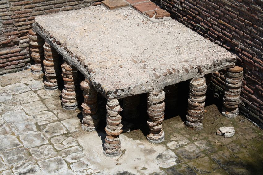
Articles

 On the history of indoor
 environment and it’s relation
 to health and wellbeing
 This article describes research and devel-
 opments in the past that had influence on
 how people thought and now think about
 indoor environment. The emphasis is on in-
 door air quality and thermal comfort.
 LADA HENSEN CENTNEROVÁ
 Keywords: Indoor Environment, Thermal
 Ing. PhD., Eindhoven University
 Comfort, Indoor Air Quality, History
 of Technology, The Netherlands,
 l.hensen@tue.nl
 From ancient times until the 18th
 century
 tions that were experienced in poorly ventilated rooms.
 Thermal Comfort - Heating Around 1700, the general idea was that breathing was
 The history of indoor environment begins 1,5 million primarily a way of cooling the heart. But it was also
 years ago when early humans began using campfires. At common knowledge that expired air was unfit for
 some point the campfire was brought inside caves and breathing until it had been refreshed. [2]
 huts. The oldest arrangement was a central fire and a
 central roof opening for smoke to escape. Later the fire The role of oxygen in breathing was pointed out by
 was moved to different parts of a dwelling and various Lavoisier (1781), even though Boyle (1627–1691),
 schemes were tried to improve the efficiency of the fire and Hooke (1635–1703) 100 years earlier (1667) had
 by using stones. However, even the best open fire was found that the supply of air to the lungs was essential
 only 20% efficient considering that most of the heat for life. The work of Antoine Lavoisier (1743– 1794)
 escaped with the smoke. Open fireplace heating was was especially important for understanding the human
 used as early as the 800s BC and became widespread metabolism, including the quantitative association
 across Europe by the 13th century. Romans already between oxygen consumption and carbon dioxide
 had underfloor heating to make the indoor climate in (CO2) release. During the following half century it was
 their palaces and spas comfortable (Figure 1). The next accepted that the concentration of CO2 was a measure
 important advance in heating which had influence on of whether the air was fresh or stale. [2]
 thermal comfort was the invention of the chimney in
 the 15th century. It took the next 200 years to be widely 19th century
 adopted. The first freestanding warm air stoves were Indoor Air Quality - Ventilation
 produced in the 17th century.[1] In 1853 Max J. Pettenkofer (1818–1901) – the
 first professor in hygiene in Munich - noted that the
 Indoor Air Quality - Ventilation unpleasant sensations of stale air were not due merely
 Throughout history, man understood that polluted to warmth or humidity or CO2 or oxygen deficiency,
 air could be harmful to health. Greeks and Romans but rather to the presence of trace quantities of organic
 were aware of the adverse effects of polluted air in, e.g., material exhaled from the skin and the lungs. He stated
 crowded cities and mines (Hippocrates, 460–377 BC). that ‘bad’ indoor air did not necessarily make people
 Throughout the medieval era, small steps forward have sick but that such air weakened the human resistance
 been done in this field. Bad air was held responsible against agents causing illness. In Pettenkofer’s view
 for the spread of diseases and for the unpleasant sensa- CO2 was not important but was an indicator of the

14 REHVA Journal – April 2018
Articles

amount of other noxious substances produced by man. Indoor Air Quality & Thermal Comfort
Pettenkofer stated that air was not fit for breathing if Possibly the most complete overview of the relationship
the CO2 concentration (with man as the source) was between indoor environment & health had Florence
above 1000 ppm and that good indoor air in rooms Nightingale (1820–1910). According to Wikipedia she
where people stay for a long time should not exceed was ‘an English social reformer and statistician, and the
700 ppm, in order to keep the people comfortable. [2] founder of modern nursing’. According to Chris Iddon
 she was ‘nurse & structural engineer’ [4]. Nightingale
The first estimate of the required minimum amount (Figure 2) wrote the first modern handbook for the
of ventilation air was published in 1836 by a Cornish nursing of sick ‘Notes on Nursing, What It Is, and
mining engineer Thomas Tredgold. He calculated that What It Is Not’ [5]. In her foreword she wrote that her
one person needed 2 l/s of fresh air for breathing and book was meant as ‘tips for women who are personally
candle burning. [3] responsible for the
 health of others’.
ASHRAE recommended in 1895 as a minimum rate
for ventilation 15 l/s per person. This ventilation rate The first chapter
was based on the work of John Billings (1836-1913), of her book focuses
medical doctor and the American authority in the field of not on patient care,
ventilation at that time. but on ventilation.
 She wrote: ‘The
For several centuries, there were two schools of thought first task of nursing:
with respect to ventilation. Architects and engineers to keep the air that
were concerned with providing comfort, absence breathes the patient
of noxious odors and carbon dioxide accumulation. as pure as the
Physicians, on the other hand, were concerned with outside air, without
minimizing the spread of disease. [3] cooling them.’ In the
 second chapter she Figure 2. Florence Nightingale.

Figure 1. The Hypocaustum. Romains system of underfloor heating.

 REHVA Journal – April 2018 15
Articles

 mentioned five essential points to ensure the health air-conditioning. Since then, air-conditioning has been
 of houses: defined as a system that must have four basic functions:

 •• Pure air •• Temperature regulation
 •• Clear water •• Humidity control
 •• Efficient waste water drainage •• Air circulation and/or ventilation
 •• Hygiene •• Air purification (filtration)
 •• Light
 Carrier designed in 1904 a spray-type air-conditioner,
 Nightingale has seen and approached the problems of a very sophisticated air washer, with which he could
 the indoor environment in its entirety. Other recom- control the absolute humidity of the air leaving the
 mendations from her, which are being rediscovered conditioner and, ultimately, the relative humidity of
 today, are: the conditioned space. In January 1906, he obtained
 the patent called ‘Apparatus for Treating Air’ [7]. (The
 •• Bring air from outside. Open your windows and term ‘air-conditioning’ was first coined by the American
 close your doors. textile engineer Stuart Cramer).
 •• (Natural) air temperature fluctuations are necessary
 to stay healthy. In 1911 Carrier presented his ‘Rationale Psychrometric
 •• Light is essential for both health and recovery. Formulae’ at a meeting of ASHRAE. This became the
 •• The body and mind degenerate without sunlight. basis for the fundamental calculations in the air-condi-
 tioning industry. His work helps to determine the precise
 In the beginning, thinking about the indoor environ- relationship between temperature and humidity in order
 ment was in the realm of philosophy. Much later, in to be able to regulate the indoor climate throughout
 the 19th century, indoor environment concerns were the year. With his scientific work, his vision of a new
 covered by two separate disciplines: medicine and industry – air-conditioning - and with his entrepre-
 engineering. neurial activities, Carrier has had a very strong influence
 on the indoor environment field (Figure 3). However,
 20th century he was never really involved in comfort-related issues.
 In the 20th century researchers were increasingly
 convinced that ventilation is mainly a matter of comfort
 and not of health. There was a growing resistance to
 heating the large amounts of outside air prescribed for
 ventilation.

 Air Conditioning – Thermal Comfort
 The beginning of the 20th century marks also the birth
 of air-conditioning, an invention that turned out to
 have a major impact on the indoor environment.
 Probably the first building with cooling (without
 using ice) is the Stock Exchange building in New
 York, USA. Alfred Wolff (1859–1909) designed the
 cooling system that used three ammonia absorption
 chillers, with a cooling capacity of 1,582 kW [6]. Yet Figure 3. An example of air conditioning industry.
 he did not become the best-known air-conditioning
 engineer.
 Indoor Air Quality
 Willis H. Carrier (1876–1950) is known as the inventor Leonard Hill (1866–1952) dedicated his life and work
 (or father) of modern air-conditioning. Carrier designed to research improving the physical well-being of people.
 his first system in 1902 to control temperature and He didn’t find any evidence that high concentrations of
 humidity in a printing plant in Brooklyn (New York, CO2 can cause discomfort and, therefore, he concluded
 USA). Unfortunately, this system did not work well and that heat and odor (caused by physical emissions) are
 the design conditions couldn’t be maintained. However, the main sources of uneasiness in rooms with poor
 this design is generally marked as the first application of ventilation [8].

16 REHVA Journal – April 2018
Articles

Using an instrument known as the ‘kata thermometer’, Thermal Comfort
he determined the cooling capacity of air movement Adolf P. Gagge (1908-1993) introduced his ‘Two-node
on the human body. This was used to monitor work- model’ in 1936. It calculates the thermal response by
place conditions in the United Kingdom, including means of two energy balance equations, one for the
the House of Commons, where Hill was concerned core node and one for the skin node. This model
that ‘cold feet and stuffy heads result - just the wrong (sometimes called Pierce model because Gagge made it
conditions for legislators’ [9]. together with his colleagues at JB Pierce Laboratories
 of Yale University) assumes that the sum of the heat
In 1923, ASHRAE Journal published the article exchange between humans and their environment
‘Determination of the comfort zone’ (Houghten & through metabolism, activity, evaporation, radiation
Yaglou) [10], in which the conditions for comfort were and conduction is zero. [13] With his model Gagge
presented on a psychrometric diagram. They used the applied the first law of thermodynamics (conservation
index ‘Effective Temperature’ (ET), which was used of energy) on man and his environment. [14] This
extensively over the next 50 years [11]. ET is defined as model was expanded later (after World War II.).
the dry bulb temperature (DBT) of a uniform environ-
ment with a relative air humidity of 50%, which would Gagge’s work helped define the study area of energy
have the same heat exchange, by radiation, convection and exchange between the human body and the immediate
evaporation, as the environment in question (Figure 4). environment. It’s application had an impact on health
 and safety at work, in the military, in space exploration
 and in the design and operation of buildings [14].

 From the early 1960s there were many researchers
 working in the field of thermal comfort. The most well-
 known and influential was Povl Ole Fanger (1934–
 2006). Fanger (Figure 5) focused on the relationship
 between the physical parameters of the environment,
 the physiological parameters of people and the percep-
 tion of comfort expressed by people themselves. In
 1970, he published his dissertation ‘Thermal Comfort’
 [15] in which he defined a new discipline: the study
 of the condition of comfort and well-being in indoor
 environments. [14] The conceptual leap introduced by
Figure 4. Effective Temperature nomogram (Yaglou). Fanger, compared to previous studies, is the introduc-
 tion of the judgment scale by people themselves.

 Using Fanger’s comfort theory, it is possible to predict to
 what extent a certain indoor environment will be expe-
 rienced by building users as ‘cold’, ‘neutral’ or ‘warm’.
 The prediction of the mean thermal sensation, which is
Constantin Yaglou1 (1897–1960) also studied the
relationship between body odor and ventilation flow.
He concluded that these odors are not really harmful to
building users and that CO2 concentration cannot be
a good indicator of the air quality in buildings. Yaglou
noted that odors are probably related to temperature
and humidity[12]. Ventilation requirements were
measured by using the human nose as a sensor.

In 1936 ASHRAE recommended 7.5 l/s per person on the
basis of work of C. Yaglou.

1 Yaglou’s original name was Yagloglou but in 1947 he shortened his surname. Figure 5. P. O. Fanger.

 REHVA Journal – April 2018 17
Articles

 associated with a combination of six environmental and Environmental movement
 personal parameters (air temperature, mean-radiant Environmental aspects largely focused on indoor air
 temperature, relative humidity, air velocity, activity quality until the 1960s. In 1962, Rachel L. Carson
 level and thermal resistance of the clothing), is given as (1907–1964) wrote her book ‘Silent Spring’. In this
 ‘Predicted Mean Vote’ (PMV-index). The PMV-index book she describes the harmful effects of pesticides on
 indicates the predicted opinion of a group of people the environment. It is widely credited with helping
 with identical metabolism and clothing regarding launch the environmental movement. Environment
 their thermal sensation. It does not predict the accept- was suddenly synonymous with outside air and indus-
 ability of the environmental conditions (Table 1). As trial environment. Environmental protection received
 a follow-up to the PMV-index, Fanger introduced the worldwide attention but IAQ (indoor air quality) in
 PPD-index (Predicted Percentage of Dissatisfied) that non-industrial indoor environments was not on the list
 does predict the acceptability (Figure 6). Fanger’s model of environmental problems.
 was developed for the applications in air-conditioned
 buildings but, from the 1980s, it was also used for other In 1973, ASHRAE published its first Standard 62 with
 applications (non-air-conditioned rooms). In other the recommended amount of supplied air of 7.5 l/s per
 words, the interpretation of Fanger’s work in practice person.
 is not entirely correct [16].
 In 1981, ASHRAE divided the recommended amount of
 fresh supply air into two categories. For non-smoking rooms
 2 l/s per person and for rooms where smoking was allowed
 10 l/s per person.
 Table 1. Scale of the PMV index.
 Many different studies have shown that indoor air
 [Source: NEN-EN-ISO 7730]
 quality is influenced by the quantity and quality of
 +3 Hot
 the supplied fresh air, pollution by people themselves
 and emissions of the materials used in buildings. More
 +2 Warm
 and more specific studies have been carried out with
 +1 Slightly warm regards to radon, tobacco smoke, VOC (volatile organic
 0 Neutral compounds), formaldehyde, (fine) dust, asbestos, dust
 -1 Slightly cool mites and other agents that influence the indoor air
 -2 Cool quality.
 -3 Cold
 Sick Building Syndrome
 With the amount of fresh supply air minimized to 2 l/s
 per person (as a result of the energy crisis in the 1970s),
 there were more and more problems with the indoor
 environment, especially in office buildings (Figure 7).
 Many different terms were used to indicate the phenom-
 enon of reported high occurrences of health problems
 and diseases. From 1982, the World Health Organization
 (WHO) used the term Sick Building Syndrome (SBS)
 and this became the most commonly used term. SBS
 relates to a number of symptoms that are experienced by
 several building occupants when they are in a building
 and which reduce or disappear completely when they
 leave the building. Since 1989, Healthy Buildings
 congresses have been organized to bring researchers from
 medical sciences together with engineers and technicians
 from practice to solve the problems that cause SBS.

 A major challenge is that research and practice mostly
 Figure 6. The relationship between PMV and PPD (Fanger) focus on individual components. It is only during

18 REHVA Journal – April 2018
Articles

 Thermal Adaptation
 The 1980s saw the start of the discussion about adap-
 tive principles related to thermal comfort. The initiator
 was Michael A. Humphreys. An English physicist
 who does a lot of research into thermal adaptation of
 building occupants. In 1998, he wrote together with J.
 Fergus Nicol, an article ‘Understanding the Adaptive
 Approach to Thermal Comfort [19]. The starting point
 of their discussion was: ‘If a change occurs such as to
 produce discomfort, people react in way that tend to
 restore their comfort’. They explain adaptation as ‘all
 those physiological, psychological, social, technological,
 cultural, or behavioral strategies people might use to try
 to secure their comfort’. Some other researchers confine
Figure 7. The overview of the recommended amount the term adaptation to that kind of physiological or
of air supply in ASHARE standards (Source: Olesen, psychological acclimatization through which a person
2011: PowerPoint-How much ventilation and how to might come to prefer or accept a different set of skin
ventilate in the future) temperature or sweat rates for comfort. [19]

 Gail S. Brager and Richard J. de Dear published in
 1997 a literature study on thermal adaptation in the
the last decades of the twentieth century that the first built environment [20] and developed an adaptive
attempts towards more holistic approaches to indoor model of thermal comfort [21] (Figure 8). This research
environmental problems were made [17]. With the was subsequently included in ASHRAE Standard 55.
holistic approach of the indoor environment, ‘soft’ The field studies made it clear that Fanger’s PMV-index
factors are also taken into account. After the decades might be too strict for non-air-conditioned buildings
in which medical doctors and engineers had investi- where users themselves could have control over the
gated the problem separately, these disciplines began to indoor environment. In other words, where people
learn from each other. In the research on Sick Building have the possibility to influence their environment (for
Syndrome many psychological studies were conducted example by opening windows).
which focused on the perception of people. Many
buildings are designed in a way that does not connect
with evolutionary old ‘software’ in our brain; i.e., the
basic laws that govern our behavior. [18] The relevant
laws are:

•• People and animals need change. This applies in
 particular to thermal comfort. A homogeneous envi-
 ronment means that people feel less comfortable.
•• Man wants to constantly intervene in his environ-
 ment. This law also applies mainly to the thermal
 comfort but also to ergonomics (furniture).
•• A meaning must be given to stimuli. For example, a
 smell that is present in the building and that cannot
 be recognized, leads to a state of chronic alarm.
•• Man always strives to have his own territory. This
 becomes a problem, for example, in open plan
 offices.
•• Man has been living in artifacts for only several Figure 8. The shift in attention to the three health aims
 centuries and this has broken his contact with the of building services that constitute complete health
 natural environment. That’s why the view to outside (Source: reference 22)
 is very important. [18]

 REHVA Journal – April 2018 19
Articles

 Before the 21st century
 From the indoor environment developments during the
 past three centuries it can be concluded that health had
 priority in the beginning. In the 18th century people
 wanted to have a healthy environment in buildings in
 order to prevent the spread of diseases. Later, the indoor
 environment problems were dominated by comfort
 issues [22] (Figure 9). People wanted to be able to
 realize comfortable indoor conditions throughout the
 year. After the oil crisis in the 1970s, the main goal
 was to save as much energy as possible on indoor envi-
 ronment conditioning. Towards the end of the 20th
 century, sustainability became very important. In the
 Netherlands, sustainability was primarily seen in the Figure 9. Indoor environment problems dominated by
 form of fossil energy. For example, Trias Energetica with comfort issues.
 special attention for energy saving (isolation of buildings)
 and generation of sustainable energy (use of solar boilers environment are being discussed, such as influence of
 and later PV panels). Only a few years ago (beginning the indoor environment on productivity or supporting
 of the 21st century) people regained interest in health health and well-being of building occupants. These are
 in the build environment. New topics regarding indoor nowadays topics which don’t belong to history yet.

 References
 [1] B. Nagengast, “An Early History Of Comfort Heating,” ACHRNEWS.com, 2001.
 [2] J. Sundell, “On the history of indoor air quality and health,” Indoor Air, vol. 14, no. 7, pp. 51–58, 2004.
 [3] J. E. Janssen, “The History of ventilation and Temperature Control,” ASHRAE J., vol. October, pp. 48–70, 1999.
 [4] C. Iddon, “Florence Nightingale: nurse and building engineer,” 2015. [Online]. Available: http://www.cibsejournal.com/
 general/florence-nightingale-nurse-and-building-engineer/.
 [5] F. Nightingale, Notes on Nursing, What It Is, and What It Is Not. 1859.
 [6] B. Roberts, “ALFRED WOLFF AIR CONDITIONING PIONEER,” 2014. [Online]. Available: http://www.hevac-heritage.org/built_
 environment/pioneers_revisited/wolff.pdf.
 [7] B. Nagengast, “Early Twentieth Century Air-Conditioning Engineering,” ASHRAE J., no. March, pp. 55–62, 1999.
 [8] L. Hill, M. W. Flack, J. McIntosh, R. A. Rowlands, and H. B. Walker, “The Influence of the atmosphere on our health and
 comfort in confined and crowded places,” Smithson. Misc. Collect., vol. 60(23), 1913.
 [9] J. Clayton, “Behind the picture: Leonard Hill and the divers,” 2014. [Online]. Available: http://www.insight.mrc.
 ac.uk/2014/08/13/behind-the-picture-leonard-hill-and-the-divers/.
 [10] F. Houghten and C. Yaglou, “Determination of the comfort zone,” ASHVE Trans 29, vol. 29, pp. 165–176, 1923.
 [11] A. Auliciems and S. V Szokolay, “Thermal comfort,” PLEA Notes, p. 66, 2007.
 [12] C. P. Yaglou, “Ventilation Requirements,” ASHVE Trans., vol. 42, 1936.
 [13] A. Gagge, “The linearity criterion as applied to partitional calorimetry,” Am. Physiol. Soc., vol. 116, no. 3, pp. 656–668, 1936.
 [14] K. Fabbri, “A Brief History of Thermal Comfort: From Effective Temperature to Adaptive Thermal Comfort,” in Indoor Thermal
 Comfort Perception: A Questionnaire Approach Focusing on Children, 2015, pp. 1–302.
 [15] P. Fanger, “Thermal comfort. Analysis and applications in environmental engineering.,” Therm. Comf. Anal. Appl. …, 1970.
 [16] J. Van Hoof, “Forty years of Fanger’s model of thermal comfort: Comfort for all?,” Indoor Air, vol. 18, no. 3, pp. 182–201, 2008.
 [17] P. M. Bluyssen, The Indoor Environment Handbook, vol. 165, no. 3. 2012.
 [18] P. A. Vroom, Psychologische aspecten van ziekmakende gebouwen. ISOR, 1990.
 [19] M. A. Humphreys and J. F. Nicol, “Understanding the adaptive approach to thermal comfort,” in ASHRAE Transactions, 1998,
 vol. 104, no. Pt 1B, pp. 991–1004.
 [20] G. S. Brager and R. J. De Dear, “Thermal adaptation in the built environment : a literature review,” Energy Build., vol. 27, pp.
 83–96, 1998.
 [21] R. De Dear, G. Brager, and C. Donna, “Developing an adaptive model of thermal comfort and preference,” ASHRAE Trans., vol.
 104, no. Part 1, pp. 1–18, 1998.
 [22] F. Franchimon, “Healthy building services for the 21st century,” doctoral dissertation, Technische Universiteit Eindhoven, 2009.

20 REHVA Journal – April 2018
You can also read