Where, When, and How mmWave is Used in 5G and Beyond - arXiv
←
→
Page content transcription
If your browser does not render page correctly, please read the page content below
1

 Invited Paper
 Where, When, and How mmWave is Used in 5G and Beyond
 Kei Sakaguchi1, 2, member, Thomas Haustein1, Sergio Barbarossa3, Emilio Calvanese Strinati4, Antonio Clemente4,
 Giuseppe Destino5, Aarno Pärssinen5, Ilgyu Kim6, Heesang Chung6, Junhyeong Kim6, Wilhelm Keusgen1,
 Richard J. Weiler1, Koji Takinami7, member, Elena Ceci3, Ali Sadri8, Liang Xian8, Alexander Maltsev8,
 Gia Khanh Tran2, member, Hiroaki Ogawa2, student-member, Kim Mahler1, Robert W. Heath Jr. 9, member

 SUMMARY and other parameters lead to the necessity for operators
 Wireless engineers and business planners commonly raise the to provide a diverse set of 5G networks.
question on where, when, and how millimeter-wave (mmWave) will be
used in 5G and beyond. Since the next generation network is not just a Among the key physical layer technologies enabling
new radio access standard, but instead an integration of networks for this efficient 5G system design, the use of mmWave
vertical markets with diverse applications, answers to the question spectrum will be coupled with network densification and
depend on scenarios and use cases to be deployed. This paper gives massive MIMO to serve as an ultra-high speed access
four 5G mmWave deployment examples and describes in chronological
 and backhaul systems. In this paper, we’ll focus on the
order the scenarios and use cases of their probable deployment,
including expected system architectures and hardware prototypes. The 28 GHz frequency band, which is planned to be used in
paper starts with 28 GHz outdoor backhauling for fixed wireless access 3GPP NR [4][5], and the 60 GHz band, which is an
and moving hotspots, which will be demonstrated at the PyeongChang unlicensed band currently used by IEEE802.11ad/WiGig
winter Olympic games in 2018. The second deployment example is a [6]. The rationale of this paper, though, can also be
60 GHz unlicensed indoor access system at the Tokyo-Narita airport,
which is combined with Mobile Edge Computing (MEC) to enable applied to future frequency bands being discussed in
ultra-high speed content download with low latency. The third example WRC-19 and later [7]. Another important 5G key
is mmWave mesh network to be used as a micro Radio Access technology is Mobile-edge Computing (MEC), which
Network (µ-RAN), for cost-effective backhauling of small-cell Base will bring information and processing closer to the
Stations (BSs) in dense urban scenarios. The last example is mmWave
 mobile users and enable low latency services.
based Vehicular-to-Vehicular (V2V) and Vehicular-to-Everything
(V2X) communications system, which enables automated driving by This paper provides an introduction to mmWave and
exchanging High Definition (HD) dynamic map information between MEC and introduces four different 5G mmW use cases,
cars and Roadside Units (RSUs). For 5G and beyond, mmWave and including a future forecast about where, when, and how
MEC will play important roles for a diverse set of applications that mmWave will be used in 5G and beyond. The question
require both ultra-high data rate and low latency communications.
 on “how” was partly already answered: mmWave will be
 key words: millimeter wave, MEC, 28GHz, 60GHz, meshed network, combined with MEC in order to allow ultra-high speed
V2V/V2X, automated driving, future forecast. and low latency communications. The answer to the
 question on “where” will be disclosed in later sections
1. Introduction with corresponding scenarios and use cases.
 The paper is organized as follows. Section 2
 5G will not be just a new radio access standard. Rather, summarizes related works and helps the reader to
the key novelty of 5G will be the integration of multiple understand state-of-the-art of mmWave technologies. In
networks serving diverse sectors, domains and Section 3 to 6, four different 5G mmW use cases are
applications, such as multimedia, virtual reality (VR) / introduced, together with the expected time frame for
augmented reality (AR), Machine-to-Machine (M2M) / market entry. Section 3 introduces 28 GHz outdoor
Internet of Things (IoT), automotive, Smart City etc. backhaul for fixed wireless access and moving hotspot.
[1][2]. A recent report states that data traffic for these Section 3 also introduces several Proof-of-Concept
new applications is expected to grow from 2016 to 2021 (PoC) demonstrations, which will be presented at the
much larger than the assumed 590% for conventional PyeongChang winter Olympics games in 2018. Section 4
applications: 770% for mobile video, 950% for mobile introduces the trial demonstration of a 60 GHz indoor
VR and 1320% for M2M/IoT [3]. The diversity of the access system combined with MEC at the Tokyo-Narita
5G applications and the diversity of the related service airport. Section 5 introduces a mmWave mesh network
requirements in terms of data rate, latency, reliability, for µ-RAN, to be used in dense urban scenarios as a cost-
 effective integration of access and backhaul. Section 6
 1
 Fraunhofer HHI, Germany. 2Tokyo Institute of Technology, introduces mmWave based V2V/V2X communications
Japan. 3Sapienza University of Rome, Italy. 4CEA/LETI Labs – for automated driving, which is expected to be one of the
MINATEC, France. 5University of Oulu, Finland. 6ETRI, Korea. largest applications of 5G and beyond. Finally, Section 7
7
 Panasonic Corporation, Japan. 8Intel Corporation, USA. provides concluding remarks of this paper.
9
 The University of Texas at Austin.
2

2. Related Works on mmWave Technologies for 5G will commercially available in 2017.
 & Beyond The 60 GHz band in combination with highly
 directional antennas is also beneficial for short range
 This section starts with the current status of mmWave small-cells backhauling. For instance, Intel has
technologies in cellular networks and also explains developed a 25 dBi beam steerable antenna in [22], in
issues related to spectrum regulation. To the author’s order to extend the coverage of WiGig up to several
knowledge, the first studies considering mmWave as a hundred meters. InterDigital has released a product using
key component for cellular 5G networks appeared 60 GHz for meshed backhaul with a maximum distance
around 2011. Samsung was an early pioneer in of 300 meters per link in [23], and has been extended by
recognizing the feasibility of mmWave for access in introducing Software Defined Network (SDN) to create a
cellular systems [8]. Prof. Rappaport and his team at flexible path on the mesh network. Overall, mmWave
NYU showed the feasibility of mmWave for outdoor backhauling /fronthauling is reasonable to support higher
access scenarios based on propagation measurements at densification of small-cells and a flexible network,
28, 38, 60 and 73 GHz [9]. Prof. Heath and his team at without the extensive costs of new cabling [24][25].
University of Texas at Austin showed the effectiveness From chipset and antenna perspective, 28 GHz
of beamforming and MU-MIMO in mmWave bands for followed the 60 GHz band. Samsung led developments
system rate improvements in cellular networks [10]. Prof. in the 28 GHz band together with NYU and developed
Sakaguchi, Dr. Haustein, and the MiWEBA project team early prototypes [26]. After the WRC-15, many chipset
advanced the concept of heterogeneous networks vendors started to develop 28 GHz technologies, which
overlaying mmWave small-cells on larger macro-cells also led to the announcement of Intel to support 28 GHz
[11], which is one of the baseline system architecture of in their 5G chipsets [27]. Qualcomm announced that the
current 5G standardizations. first commercial products featuring 5G NR modems
 It is very likely that 28 GHz will be used for the first expected to be available in 2019 and it will initially
5G deployments in the South Korea, US and Japan, support the 28 GHz band with 800 MHz bandwidth via
although 28 GHz itself was excluded from the candidates 8x100 MHz carrier aggregation [28]. IBM released 32-
of IMT bands in WRC-15. ITU-R selected at the WRC- element dual polarized phased array with fully integrated
15 several frequency bands above 24.25 GHz as transceiver IC in 28 GHz band [29], and NEC released a
candidates for 5G [12] based on the IMT feasibility massive MIMO antenna at 28 GHz band with 500
study for bands above 6 GHz [13] and the current usage elements, which will be used in the earliest deployment
of spectrum in all nations. Then, the FCC in the U.S. of 5G in Japan [30].
opened in total nearly 11 GHz of spectrum above Recently, several organizations realized mmWave
27.5 GHz, including unlicensed spectrum at 64-71 GHz, technology components and mmWave network
which resulted in the US leadership of world-wide 5G integrations. The MiWEBA project has demonstrated the
developments [14][15]. The same year, 5GMF [16] and integration of LTE and a 60 GHz WiGig access system,
EC [17] revealed their plans for 5G frequency bands in using the LTE & WLAN aggregation protocol defined in
Japan and Europe, which are summarized in Table 4 in 3GPP Rel. 13 [31]. The Tokyo-Narita international
Section 6. Even though the bands around 28 GHz are airport announced the launch of a Kiosk service in 2018
prioritized for 5G in the South Korea, US and Japan, using 60 GHz WiGig technology, in order to download
there are obviously frequency band discrepancies in (or upload) large amount of data instantaneously [32]. In
different nations. In order to solve this problem, the US, Verizon and Samsung announced their service at
discussion in 3GPP proposes to treat spectrum from 28 GHz, starting from September 2017 [33] and, together
24.25-29.5 GHz as one single band and adapt the with Ericsson, Nokia, Cisco, Qualcomm and Samsung,
actually used channel based on the local regulation by the Verizon Technology Forum was initiated. T-Mobile
numerology. and AT&T are performing similar trials in the US
 Due to its technology readiness level, 60 GHz WiGig is together with Ericsson, Nokia and Samsung. In South
also an important technology for 5G systems. After the Korea, SK Telecom, Ericsson and BMW executed a trial
standardization of IEEE802.11ad/WiGig in 2012, tri- of the 1st 5G connected car using 5G V2X [34], where
band chipsets supporting 2.4 GHz, 5 GHz and 60 GHz they used the 28 GHz band to deliver UHD 4K video
bands were released by Intel and Qualcomm [18][19]. from a 360°-camera. In Japan, KDDI and Samsung
Panasonic developed in 2014 a first WLAN access point performed handover experiments in the 28 GHz band
(AP) prototype using 60 GHz [20] and recently, [35]. Also, NTT docomo, together with Ericsson and
commercial products using WiGig became available on Intel, are planning 5G trial environments using 28 GHz
the market. To ensure interoperability, WiGig became in Tokyo [36]. ETRI as a pioneer in millimeter-wave-
part of the Wi-Fi alliance in 2013 and the certification based railway communications technology successfully
program was established in 2016 [21]. As a result, one gave the second field trial of Mobile Hotspot Network
can expect that the first WiGig embedded smartphones (MHN) prototype system at the Seoul subway line 8 in
3

February 2017 [37], which was the world first modification of the numerology to increase the
millimeter-wave prototype system demonstrated in a subcarrier spacing. This result in a cost effective
running subway train with a peak data rate of 1.25 Gbps. adaptation of existing technology to accommodate the
 Although mmWave technologies at 28 GHz and new 5G requirements as well as the opportunity of a
60 GHz have the potential to be used for early quick launch of new features for wireless backhaul links.
deployment of 5G in the South Korea, US and Japan, Recently, South Korea, US, and Japan have been
there is a need for deeper discussions regarding the speeding up development of 5G services that use 28 GHz
scenarios, use cases and corresponding enabling under the umbrella of the 28 GHz initiative. It is already
technologies. We will start in Section 3 with the related planned in South Korea to demonstrate world first 5G
5G CHAMPION project [38], which will use 28 GHz services in PyeongChang winter Olympic games in 2018.
technology at the PyeongChang winter Olympics games However, real deployment strategy of 28 GHz band for
in 2018 [39] and we will then go to 60 GHz technology, both static and mobile 5G service provisioning will be
which will be used at the Tokyo-Narita airport during the consolidated after the extensive real-field
Tokyo Summer Olympics games in 2020 [40]. From experimentation at the PyeongChang Olympic games.
Section 4, we will widen our scope based on the 5G- 5G CHAMPION project [38] takes the challenge of
MiEdge project [41] and study the union of mmWave providing the first fully integrated and operational end-
and MEC enabling ultra-high data rate and low latency to-end 5G prototypes to the PyeongChang Olympic
applications. This concept is extended to future 5G games in 2018. This effort is a major leap ahead
topics, in Section 5 to a mmWave mesh network and in compared to existing and planned punctual technology
Section 6 to a mmWave based V2V/V2X system. trials, such as PoC platforms focusing on 28 GHz
 mmWave communication. This section describes the
 overall set-up of the PoC in the 5G CHAPION project
3. 28 GHz Outdoor Backhaul for Fixed Wireless including a synergetic combination of technologies such
 Access and Moving Hotspots as beamforming based mmWave, virtualized
 infrastructure, software reconfiguration across the entire
3.1 Introduction to 28GHz Band stack, and high-speed solutions. More details on the
 foreseen PoC are given in [42].
 Today is not clear yet which mmWave bands will be
first adopted by 5G technologies. Nevertheless, the ITU- 3.2 Scenario/Use Cases and Requirements selected in 5G
R and 3GPP have aligned on a plan for two phases in the CHAMPION Project
5G standardization. The first phase will end in
September 2018 and South Korea, US, and Japan have The 5G CHAMPION project leverages cutting-edge
agreed to trial solutions on 28 GHz band having the solutions of mmWave backhauling, mmWave
challenging target to first roll out of 5G services in real transceivers with reconfigurable antennas, localized
environment at the 2018 PyeongChang winter Olympic evolved packet core supported by distributed or
games. This might push 28 GHz into consumer products centralized MEC with caching, media and streaming
before the standardization bodies finalize the 5G functionalities into a unique platform capable to support
standards even if ITU-R excluded the 28 GHz band from a wide-range of 5G specific use cases, summarized in
the candidates for WRC-19 because such band is adopted Table 1.
today for satellite communications. More specifically, the first use case refers to a
 The choice of the 28 GHz band is motivated by several stationary multi-RAT hotspot connected via mmWave
reasons. First, there is extensive licensed but backhaul to the 5G European testing network. The
underutilized mmWave spectrum around 28 GHz bands objective is to demonstrate the capability of providing
that have been shown to support cellular broadband connectivity (100 Mbps minimum). In this
communications in the range of 500 meters [26]. Second, regard, the proposed strategy is to utilize high capacity
28 GHz band is still useful to create multipath mmWave wireless backhaul to increase coverage and
environments compared to higher frequencies and can be infrastructure density, heterogeneous radio access
used for non-line-of-sight communications. Moreover, towards the end users, and distributed SDN and NFV in
an additional important advantage of exploiting 28 GHz the virtual EPC to optimally orchestrate services.
band for wireless backhauling is the possibility of reuse The second use case tackles the feasibility of ultra-high
3GPP LTE functionalities. For instance, 3GPP LTE data rate over mmWave link. In this case, the objective is
allows to reuse the LTE physical layer, originally to reach 20 Gbps data rate over mmWave link and, to
designed to operate at carrier frequencies around 2 GHz, this end, the challenge is to develop efficient hybrid
and applied it to higher frequencies up to 40 GHz for analog-digital beamforming as well as higher order
small cell backhauling [5]. This requires small modulation solutions.
4

 The third use case addresses the problem of content 3.3 Proof-of-Concept at PyeongChang Winter Olympic
distribution in high-speed trains (up to 500 km/h) and Games
real-time video streaming in slow/medium moving
hotspots (bus, tram, etc.). To this end, key technologies 3.3.1 Overall Concept of Proof-of-Concept
are mmWave wireless backhaul, beam switching, MIMO
and heterogeneous access, and distributed virtual EPC. The 5G CHAMPION PoC will showcase 5G with 28
 Finally, the last two use cases to be demonstrated in GHz dedicated technology during the PyeongChang
PyeongChang Olympic games focus on short-latency winter Olympics games for use cases: (i) short latency
(
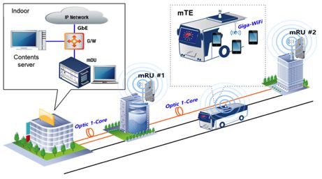
5

network side, is made of the MHN NodeBs (mNBs) Carrier frequency 26GHz
consisting of MHN Digital Units (mDUs) and the MHN Code rate 0.8
Radio Units (mRUs). The second, on the client- or the
 Transmission scheme 2x2 MIMO
moving hot spot cell-side, is made of the MHN Terminal
Equipment (mTE) mounted on a vehicle, which is
primarily responsible for mobile wireless backhauling The link-level simulation result in Figure 3 shows that
between the mRU in a mNB and the mTE. The mTE is the system is able to achieve average spectral efficiency
connected to onboard access links (e.g., Wi-Fi) for the of up to 10 bps/Hz in the case of 2x2 MIMO. Although
users inside a vehicle. The mRU is designed to operate in only one mTE will be used during the demonstration in
unlicensed frequency bands in the range of 25~26 GHz, PyeongChang, it is still possible to achieve a data rate of
which is referred to as the Flexible Access Common up to 5 Gbps considering the system bandwidth of 1 GHz.
Spectrum (FACS) in South Korea.
 In order to offer various broadband services inside a
fast moving vehicle, the South Korean backhaul system
adopts several advanced technologies [43], including a
novel frame structure supporting carrier aggregation
(CA) and enabling high-performance handover as well as
digital MIMO technology using polarization antennas.
As shown in [43], each aggregated carrier, generally
referred to as a Component Carrier (CC), has a
bandwidth of 125 MHz, and South Korean backhaul
network allows the aggregation of a maximum of eight
CCs to attain a total transmission bandwidth of up to
1 GHz. Besides, in order to further improve spectral
efficiency, fixed-beam dual linearly-polarized antenna
arrays with 4×4 (16 dBi gain) and 8×8 (21 dBi gain)
elements are used on transmit and receive antennas
respectively, to implement digital MIMO as shown in Figure 3. Link-level performance evaluation of Korean backhaul
Figure 2. network

 The European backhaul base station works in the
 frequency band 26.5 – 29.3 GHz and implements OFDM
 encoding and digital MIMO [44]. Analog beamforming
 will be implemented by considering two different
 electronically steerable antenna technologies, one based
 on the classical phased array architecture with phase shift
 inside the transceiver and the other considering a
 transmit array antenna working similar like a dielectric
 lens in optics but allowing adaptive beam forming
 electronically via a control interface.
 The phased array solution is targeted for short to very
 Figure 2 Antenna configurations of South Korean 28 GHz long range operation with sophisticated power/dynamic
 backhaul testbed.
 range control both in TX and RX that would allow
 In order to evaluate the link-level performance of South flexibility needed in backhauling to the local hotspot
Korean backhaul network, a link-level simulation was over a large area. RF hardware includes two separate
conducted under the simulation parameters listed in the antenna units each having dual-polarized antennas for
Table 2 and Cross Polarization Discrimination (XPD) of four independent transceiver chains from the antenna
50 dB referring to the recent ray-tracing simulation [44].. into baseband. State-of-the-art power amplifiers can
 provide EIRP in the range of ~60 dBm or even beyond
Table 2 Simulation assumptions for performance evaluation of depending on the modulation for long range connections.
South Korean backhaul network The antenna gain of the phased array can be further
 Parameters Setting increased using an external beam collimator that can be
 Multipath-cluster channel model controlled electronically.
 Channel model Figure 4 presents a block diagram of a possible solution
 with Rician fading channel
 K-factor 20dB
 for range boosting. More specifically, the antenna of
 backhaul base station can be designed with an
6

electronically reconfigurable transmit array antenna with 4. 60 GHz Indoor Access with Mobile Edge
analogue beam-forming capability. A transmit array is Computing
typically composed of a focal source illuminating a flat-
lens composed of phased unit-cells. By tuning the phase- 4.1 Scenario/Use Cases and Requirements
shift on each unit-cell, for example integrating p-i-n
diodes [45], the radiated beam can be collimated or mmWave access using 60 GHz unlicensed band in
deviated into a desired direction. The electronically indoor private scenarios is anticipated to be deployed in
steerable flat-lens is directly integrated into the radio near future. The scenarios do not only include homes and
front-end and feeding antennas are positioned in focal offices, but also areas such as airports, stations, trains,
point of the electronic lens as in Figure 4. buses, stadiums, museum, and shopping malls, where
 Electronically steerable flat-lens mobile operators have difficulties to deploy their BSs
 directly. Although the size of such areas is limited,
 Mechanical interface

 Beam-steering control signal
 mobile users are expected to transfer large amount of
 video content at railway stations or airports, or use AR
 applications in stadiums and shopping malls. Therefore,
 Focal source in such an area, the combination of mmWave and MEC
 becomes very important to achieve both low latency and
 high data rate requirements. In this section, we list some
 RF transceiver use cases/scenarios where the combination of mmWave
 and MEC can enrich the user’s quality of experience by
 following the discussions in the 5G-MiEdge project [41].
 Base Band Unit Steering Control Unit
 Digital processing unit
 4.1.1 Cache Prefetching

 To download large volumes of data using mmWave
Figure 4 Schematic view of the backhauling base station with access, cache prefetching based on predictions of users’
electronically steerable transmit array
 context is a key strategy to improve users experienced
 latency even with poor backhaul links. In some cases,
 The analogue beamforming capability of a 400-element
 caching may move together with the user, like a liquid.
transmit array operating in the band 27.4 – 31.7 GHz has
 This may happen for example for users in a metro train
been recently demonstrated in [44]. The antenna is based
 downloading videos or large data files. In such a case,
on a 1-bit (two tunable phase-states) unit-cell [45] and
 MEC servers associated to APs positioned in metro
works in circular polarization with a maximum broadside
 stations or along the metro rails may orchestrate video
gain of 20.8 dBi. The measured scanning losses are equal
 prefetching along the predicted positions of the users, so
to 2.5 and 5 dBi for a 40° and a 60° tilted beam,
 as to deliver these contents with very low latency. The
respectively. A linearly-polarized transmit array
 information about radio channel capacity, number of
prototype working in the band 24 – 30 GHz is
 connected users, and type of users’ requests is
developing to cover both the South Korean and European
 fundamental to orchestrate the operation of nearby MEC
frequency bands. The simulated results of its analogue
 assisted APs. Most of operations needed for services
beamforming capability are presented in Figure 5.
 provisioning and network optimization are recurrent,
 context-dependent and too often re-executed. To exploit
 30 this property, [46] proposes an extension of the cache
 20 prefetching, the computational caching, in which power
 consumption and service delay of mobile edge
 Magnitude (dBi)

 10
 computing are further reduced by caching popular
 0
 computations.
 -10

 -20

 -30 4.1.2 Augmented Reality
 -40
 -80 -60 -40 -20 0 20 40 60 80
 θ (deg) AR services enrich a user’s experience when entering a
Figure 5 Simulated analogue beamforming capability of the linearly- point of interest, like an airport, a museum or a sport
polarized transmit array developed in 5G CHAMPION at 28 GHz (E- event, by providing additional information to the user
plane gain radiation pattern). about what they are currently experiencing. AR
 applications need to be aware of the user’s position and
7

the direction they are facing through, for example, their multi-input/multi-output (MIMO), and mmWave
camera view. Starting from such information, AR communications. Merging these physical layer
applications create additional information, in the form of technologies with MEC creates a very powerful system.
video, sound, etc., and deliver it to the user in real-time. Figure 6 shows a system example where mobile users
If the user moves, the information is refreshed and (equipped with low data rate 2.4/5 GHz WLAN or LTE)
follows the user. This is a service that is naturally can get proximity access to information technology
localized. It requires a high computational cost and low services, managed by MEC servers installed in nearby
latency. Hosting such AR services on a MEC platform APs, through high data rate mmWave links. At the same
associated to a mmWave AP is a key strategy to create time, mmWave links facilitate the orchestration of
this computationally demanding supplementary multiple MEC servers through high data rate mmWave
information near the mobile user and deliver it within the backhaul connecting cloud-enhanced APs, possibly
required low latency requirements exploiting the very complementing wired backhauling [49]. Clearly, an
fast data transfer of mmWave links. effective cache prefetching or instantiation of virtual
 machines serving mobile applications requires local
4.1.3 Computation offloading prediction of users’ behavior and accurate estimation of
Running computationally demanding applications on the popularity indices of most downloaded files, possibly
mobile devices often leads to unpleasant user experience varying over time [50]. This requires the extraction of
associated to the rapid discharge of the battery. Since the big data analytics in cloud-enhanced APs, possibly
advancement of battery technology is not as fast as the coordinated through high data rate mmWave backhaul
development of new applications, a possible way out is links.
to offload intensive computations on nearby servers,
possibly located close to the access points. An effective
deployment of computation offloading greatly benefits
from the introduction of mmWave links and MEC
servers able to orchestrate the deployment of virtual
machines serving the users’ needs when and where
appropriate [47]. Computation offloading is also
particularly useful to augment the capabilities of tiny
sensors, in the IoT scenarios, which have very limited
computation and storage resources.

4.2 Unification of mmWave Access and Mobile Edge
Computing Figure 6: System architecture example composed of mmWave
 access and mobile edge computing

MEC has been recently identified as an ecosystem
 Adopting a user/application-centric point of view, if a
enabling low latency and energy efficient proximity
 user is accessing the network to run an application
access to information technology services from mobile
 remotely, the most important thing is that the user gets a
users [48]. The goal of MEC is to bring cloud-computing
 service with a good Quality of Experience, say for
capabilities, including computing and caching, at the
 example low latency. Latency, as perceived by the user,
edge of the mobile network, within the Radio Access
 includes time delay for data transfer plus the time
Network (RAN) and in close proximity to mobile users.
 necessary to run the application, plus maybe access to
This is obtained by empowering APs with additional
 remote files. This suggests that the selection of the AP as
storage and computation capabilities, and coordinating
 well as the server where to instantiate the virtual
the work of nearby cloud-enhanced APs in order to serve
 machines running the application should be optimized
the mobile users as efficiently as possible. This gives rise
 jointly under a global latency constraint.
to a fully scalable application-centric system, where
 The use of multiple mmWave links clearly helps in
cache prefetching and computation offloading are
 providing fast access to local cloud computing services
brought as close as possible to the end user to reduce
 to multiple users distributed in a target area
latency and energy consumption. Clearly, MEC is most
 simultaneously. One of the impairments of mmWave
effective in delivering context-aware services to mobile
 links is channel intermittency, due to sporadic blockage
users, but it also helps deploying an effective caching
 due to obstacles or interference from mobile users
and distributed computing strategy.
 observed from very similar angles by the APs. To
 At the physical layer, some of the key technologies
 counteract blocking events, it is useful to establish
enabling the large data rate increase foreseen in the 5G
 multilink communications, so that a user may access
roadmap are: dense deployment of radio APs, massive
 multiple APs at the same time, depending on channel
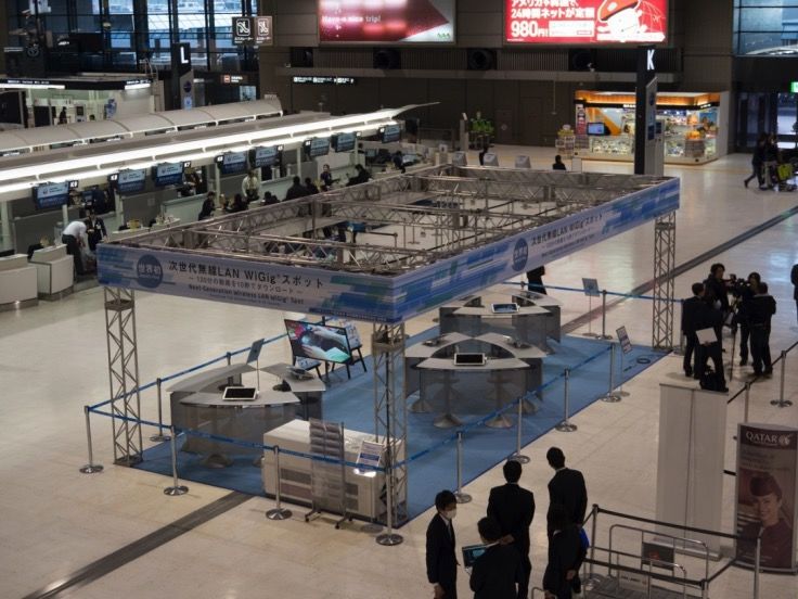
8 conditions [20][51]. beam2 beam3 beam4 beam5 beam6 20 beam1 beam7 4.3 Prototype of mmWave Access with MEC at Narita 15 Airport 10 EIRP [dBm] As a preliminary work toward MEC through mmWave links, a multi-user mmWave access employing IEEE 5 802.11ad / WiGig [6] based APs is developed [52]. Figure 7 shows the AP prototype. The RF module 0 integrates 60 GHz transceiver chip set with four element Tx/Rx beamforming, which provides about 120° beam -‐5 steering range. Combining three RF modules, the AP -‐10 achieves 360° wide area coverage while providing up to -‐90 -‐60 -‐30 0 30 60 90 three concurrent links by using either the same frequency Angle [deg.] channel or different frequency channels. Three RF Figure 8: Measured output power with different beams (at modules and the control board (which integrates a CPU, 58.32 GHz) SDRAM, external Eathernet interface, etc.) are housed in the 80 x 150 x 150 mm unit. Each RF module can handle Figure 9 shows the prototype network system. Three up to four stations (STAs), therefore accommodating a APs are wired with 10 Gbps Ethernet cables. The local maximum of 12 users by the single AP. Figure 8 shows content server acting as a edge cloud (cache) in this the measured output power of the RF module in the system bundles four 10 Gbps Ethernet cables to achive azimuth direction, offering 7-step beam steering with 40 Gb/s maximum throughput. The AP controller (APC) +20 dBm maximum effective isotropic radiated power manages beamforming control and handover between RF (EIRP). modules and multiple APs. This is done by collecting Rx 45mm signal quality (signal-to-noise ratio) for each beam Antenna direction periodically, and select the opitmum mmWave link based on the beam routing table which includes the 35mm sector index (i.e. the beam direction index), MCS (modulation and coding scheme) and the Rx signal RF Module quality [20][52]. 150mm The prototype network system was set up in Narita International Airport as shown in Figure 10. Three APs were installed at a 2.5 m height, providing 10 x 5 m area 80mm coverage. To minimize interference among multiple APs and STAs, different frequency channels were allocated Control board for each of the three RF modules within the APs. As 14cm Exterior STAs, nine 4K tablets were placed on counter desks at a Figure 7: Prototype of 60 GHz IEEE802.11ad / WiGig access point 1.0 m height. They are equipped with IEEE 802.11ad / WiGig USB dongle prototypes to establish ultra-high speed 60 GHz wireless links with APs. The STA achieves 1.7 Gbps maximum throughput, enabling to download a compressed two hours high- resolution video content (2 GB) within 10 seconds. During the nine day open period, 816 participants joined the experimental demonstration, and 99.3% of the positive feedbacks (high expectation for practical realization) were obtained. Future work includes architecture design of the whole system to the cloud, integration of caching/prefetching capability, etc. in order to realize ultra-high speed and low latency service delivery, which is resilient to network bottleneck such as backhaul congestion to the cloud.
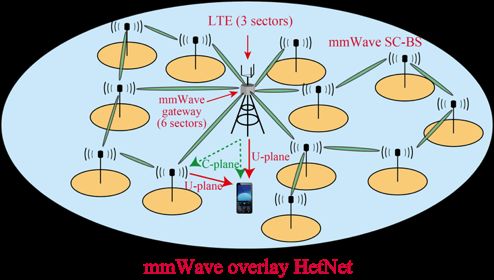
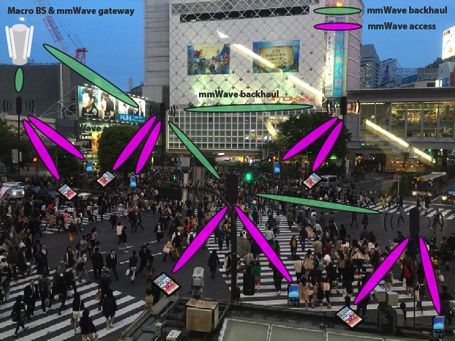
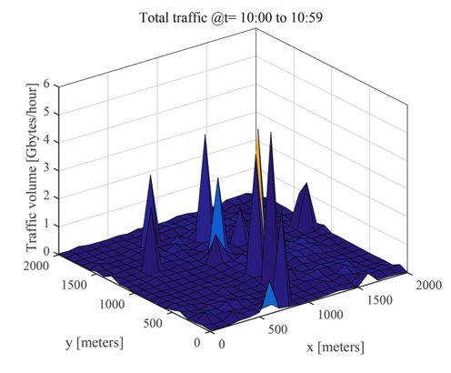
9

 Cloud

 Gateway

 Network Switch 40Gb/s

 Content Server
 1Gb/s
 10Gb/s
 AP1 AP2 AP3
 AP Controller
 (APC) 60GHz APs 2.4/5GHz AP
 Implemented as experimental demonstration

Figure 9: Prototype network system with 60GHz access and edge
content server

 AP1 to AP3 Figure 11: An example of dense urban scenario around Shibuya
 station in metropolitan Tokyo

 Figure 12 and Figure 13 show measured data of mobile
 traffic in 2014 around a famous station in metropolitan
 Tokyo [53]. Figure 12 shows the spatial traffic
 distribution in one hour in that area from 10:00 to
 10:59 AM. From the figure, it is obvious that the traffic
 2.4/5GHz AP distribution was not uniform and there were several
 hotspots. Figure 13 shows the time variation of the total
 traffic in this area. Since it is around an urban station, the
 Network Switch traffic in midnight was very low, while that of daytime
 AP Controller
 Content Server was very high. In this measurement, the average traffic

 demand per user was about 62 kbps and total area traffic
Figure 10: Experimental Demonstration at Narita International
Airport at peak hour was 44 Mbps. In the following simulation
 examples, these numbers are multiplied by 1000 by
 considering future traffic in the era of 5G.
5. mmWave Mesh Networks for µ–RAN In such an environment, network densification with
 many number of mmWave small-cell BSs (SC-BSs)
 overlaid on the current LTE cells is effective to
5.1 Scenario/Use Cases and Requirements
 accommodate traffic in peak hours as drawn on Figure
 11 [11]. However, many number of SC-BSs leads to the
 In dense urban scenario which is one of the important problem of high capital expenditures (CAPEX) and
scenarios in 5G, network densification is necessary operating expenses (OPEX). One solution to relax the
because of the high traffic volume generated not only by problem is to use mmWave mesh network for the
smart phones and tablets but also by augmented reality backhaul network of SC-BSs as in the 5G-MiEdge
information such as sensors and wirelessly connected project [41]. By using the mmWave mesh network, the
cameras. Typical environments are open squares, street CAPEX can be reduced by removing deployment cost of
canyons, stations, etc., where users tend to gather and wired backhaul. Furthermore, the OPEX can also be
move as large and dynamic crowds while want to keep reduced by introducing dynamic ON/OFF and flexible
connectivity to the cloud. Figure 11 shows one example path creation in the backhaul network in accordance with
of such scenario around Shibuya station in metropolitan the time variant and spatially non-uniform traffic
Tokyo. distributions [54]. Such flexible control of the backhaul
 network is enabled by SDN technology using out-band
 control interface over the LTE [55][56]. In summary,
 mmWave mesh backhaul with SDN comes into place as
 one suitable candidate for dense urban scenarios owing
 to its ultra-wide bandwidth and deployment flexibility
 with low cost.
10

 Figure 15. As it is hard to optimize ON/OFF status of
 SC-BSs and backhaul paths all at once, the algorithm
 involves three steps. In the first step (i), the initial
 ON/OFF status of SC-BSs is determined based on the
 traffic demands per SC-BS. In the next step (ii), initial
 paths of backhaul network are created to minimize power
 consumption. If isolated SC-BSs exist even after step (ii),
 the final step (iii) re-activates remaining SC-BSs in an
 energy efficient manner so as to transfer the traffic for
 the isolated SC-BSs. Control signaling to manage
 ON/OFF status of SC-BSs and to create physical paths
 between them are transmitted over the LTE as an out-
 band control plane. As such, a dynamic and energy
 efficient mmWave mesh network is formed.

Figure 12: Spatial distribution of the measured traffic in one hour

 Figure 14: mmWave mesh network overlaid on a macro cell

Figure 13: Time variation of the measured traffic throughout a day

5.2 mmWave Mesh Network with Traffic & Energy
Management Algorithm

 Figure 14 shows an example of mmWave mesh
network to be used in the dense urban scenario. In Figure
14, mmWave SC-BSs are overlaid on a LTE macro cell
to play a role of integrated backhaul and access with Figure 15: Traffic & energy management algorithm
three or four sectors in both access and backhaul. The
LTE macro BS plays a role of mmWave gateway as well
 5.3 Simulation of mmWave Mesh Network
in the cell to accommodate time-variant and spatially
non-uniform traffic by forming a mmWave mesh
network. Namely, a set of LTE macro BS and mmWave This section shows several examples of simulation
SC-BSs forms a µ-RAN for the target environment. The analysis for mmWave mesh networks controlled by the
prominent objective of the traffic & energy management abovementioned algorithm. In this numerical analysis,
algorithm is to reduce energy consumption of mmWave several macro cells with ISD of 500 m are assumed to be
mesh network by switching off as many SC-BSs as deployed within the 2000 m square areas in Figure 12
possible in an area while satisfying users’ traffic and one macro cell is selected as the evaluation cell.
demands. One example of such traffic & energy Other simulation parameters are shown in Table 3.
management algorithm proposed in [54] is shown in
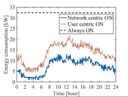
11

 Table 3: Simulation parameters.
 Parameter LTE mmWave SC-BS
 Bandwidth 10 MHz 2×2.16 GHz
 Carrier freq. 2.0 GHz 60 GHz
 Antenna gain 17 dBi 26 dBi
 Antenna height 25 m 4m/25m (SC-BS/GW)
 Tx power 46 dBm 10 dBm
 Beam pattern 3GPP IEEE802.11ad
 Path loss 3GPP [11]
 # of BSs 1 90
 Noise density 174 dBm/Hz

 Examples of the formed mmWave mesh networks are
shown in Figure 16. As there are few users in the
evaluation area at 3 AM, only a few mmWave SC-BSs
are activated. In this case, since there are enough
resource blocks in the LTE, most of the users are
connected to the macro BS, while users with very high
traffic demand at the right-bottom activate SC-BSs. On
the other hand around 3 PM, a hotspot appears in the
upper-left zone. We can see some backhaul links formed
from gateway to the hotspot, showing the effectiveness (b) Formed mmWave mesh network at PM 3:00.
 Figure 16: Dynamic formation of mmWave mesh network
of the traffic & energy management algorithm against
the locally intensive traffic.
 The analysis of power consumption is shown in Figure
 17. Here, three types of criteria for SC-BS activation are
 compared. The first one is “Network centric ON” shown
 in Section 5.2. The second is “User centric ON” in which
 mmWave SC-BSs are turned on based on the location of
 users regardless of the traffic demand. The last one is
 “Always ON” without considering ON/OFF switching.
 The figure shows the performance of total power
 consumption against dynamic traffic variation
 throughout a day. The power consumption includes both
 of the access and backhaul, which is defined as follows,
 !!"

 Energy  consumption = !!" !" + !!"" !""
 !
 where !" , !!" , and   !!"" represent the number of
 mmWave SC-BSs, the number of ON sectors and that of
 OFF sectors of  th mmWave SC-BS respectively. From
 the figure, the effectiveness of the traffic & energy
 management algorithm is obvious especially in midnight.
 It is also noted that the Network centric ON reduces the
 energy consumption about a half by control the
 (a) Formed mmWave mesh network at AM 3:00.
 association point of users adaptively within the µ-RAN.
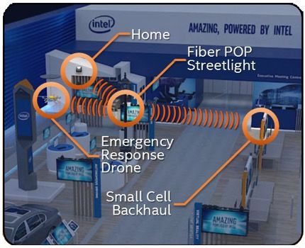
12

 degrees azimuth and +/-30 degrees elevation steering
 ability. Some antenna steering patterns are shown in
 Figure 20. It consumes about 20 W system power. At
 200 m in line-of-sight distance, up to 2 Gbps IP
 throughput could be achieved.

 Figure 17: Performance of total energy consumption
 Figure 19 Antenna geometry of mmWave PoC platform

5.4 Prototype of mmWave Mesh Nodes

At the last part of this section, we’ll introduce prototype
hardware to be used as the mmWave mesh node. Figure
18 is showing the latest compact universal mmWave
platform supporting the IEEE 802.11ad/WiGig [6]
developed by Intel. This mmWave PoC platform can be
used both for flexible backhauling with point-to-point
symmetrical transmission links up to 400 m coverage
with capability of adaptive beam switching and also for
access with asymmetrical transmission links between AP
and STAs with limited capability of beam gain at the (a) Azimuth patterns.
STA sides supporting coverage up to 100 m with the
same throughput.

 Figure 18 Prototype hardware for mmWave mesh node

Figure 19 shows the antenna geometry of the mmWave (b) Elevation patterns.
 Figure 20 Measured antenna steering patterns with different
PoC platforms. This generation is designed with compact
 beams
form factor, new radio modules, better antenna
characteristics, and in-build mini PC (Intel i5 NUC) with Finally, Figure 21 shows a photo of mini mmWave mesh
Linux device drivers. The WiGig modem on the mini PC network using six mmWave PoC platforms exhibited at
drives 8 radio modules with 16 antenna elements each. Mobile World Congress 2017. At the center of the photo,
The 8 radio modules are used jointly to form a 128- there is a streetlight with Point-of-Presence (POP) of
element antenna array in a cost efficient way. A FPGA is fiber backhaul. On the top of streetlight, three mmWave
used to process the commands from the WiGig modem, platforms are used to act as a gateway of mmWave
and send different commands to 8 radio modules for networks by providing three mmWave backhaul links.
packet transmission, beamforming, etc. As a result, the The other three platforms are located at a SC-BS (right),
prototype has about 41 dBm EIRP, 6 degrees azimuth at a home (left top), and at a drone (left) to be connected
beam width, 10 degrees elevation beam width, and +/-60
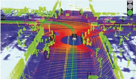
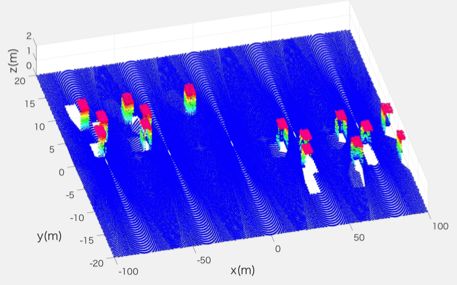
13

with the mmWave gateway via backhaul links. It is reported in [61] that Google’s automated car gathers a
planned to integrate SDN capability on this platform in total of about 6 Gbps of sensor data, which includes
near future. LiDAR and other sensors, in order to out automated
 driving into practice. [62] summarizes in general for
 automated driving the required data rates of automobile
 sensors, i.e. 80-560 Mbps for LiDAR sensors or 160-320
 Mbps for cameras sensors. Even though the final values
 depend on the resolution of the actual HD map, an
 estimation of 1 Gbps appears reasonable as a typical data
 rate requirement for exchanging HD map information via
 V2V/V2X links. Indeed, mmWave seems to be the only
 means to provide such high data rates to vehicles [71].
 Cooperative perception is realized by exchanging
 sensor data between vehicles and Roadside Units (RSUs)
 and is necessary in order to widen or enhance the
 visibility area of HD maps [63][64]. This concept allows
 a more accurate localization of objects and more
Figure 21 mmWave mesh node to provide three different backhaul important, due to the bird's eye view that can be derived
 links exhibited in MWC2017 from sensor fusion, prevents that objects remain not
 visible and undetected, due to the ego-perspective of the
 sensors mounted on the vehicle. This external object
6. mmWave based V2V/V2X for Automated Driving detection capability is particularly critical for a safe
 realization of automated driving in complex urban
6.1 Scenario/Use Cases and Requirements environments. The communication range supported by a
 cooperative perception system can be determined by the
 Automated driving is one of the three most important braking distance of vehicles. As an example, [65][66]
applications of future 5G systems [57]. The 1st phase of estimate 100 meters as a braking distance (including a
5G Vehicle-to-Vehicle (V2V) and Vehicle-to-Everything safety increment distance) for the emergency stop of a
(V2X) communications aims at driver assistance systems generic sedan car at 70 km/h, which can be seen as the
and exchanges messages either directly between vehicles maximum speed in urban city environments. This
or via appropriate infrastructure [58]. These messages braking distance estimate could be raised to 150 meters
are transmitted in case of an emergency or as so-called for buses or trucks. Hence, the HD map exchange system
awareness messages, which contain information such as should support a communication range of at least 150 m
location, speed and heading direction. The 2nd phase of for emergency braking applications. This number is to
5G V2X aims for automated driving applications, where some extent comparable to the numbers given by [67].
automated control software become primarily At the end, latency is the most crucial communication
responsible for monitoring the environment and the system parameter in order to realize a stable control. It’s
driving vehicles, referred to as Levels of Automation well known that latency and data rate are a tradeoff for
(LoA) in the range 3 to 5 [59]. the case of video or LiDAR data transmission. The latest
 Automated driving systems require highly resolved and video data compression techniques reduce the data rate
dynamic maps to maneuver the vehicles safely, in to one-tenth of the raw data rate. Video compression
particular as a means to provide decimeter localization though leads to latencies higher than the 10 ms required
which is not achieved by typical consumer-grade satellite for automated driving [57]. Furthermore, raw (or nearly
navigation equipment. As the resolution of current 2D raw) data is likely to be needed for interpretation by
maps coupled with inaccurate position information is not machine learning algorithms and has additional value for
sufficient, high resolution and real-time maps, also called liability reasons in case of an accident [63].
dynamic High Definition (HD) maps, become In summary, the enhanced V2V/V2X communication
indispensable [60]. Figure 22 shows an example of an targeting automated driving requires a data rate of
HD map generated with a LiDAR (Light Detection And 1 Gbps per link, end-to-end latency of less than 10 ms
Ranging) sensor, which is used to monitor the car per link and a communication range of 150-300 m, to put
surroundings and display the same as a high-resolution safe automated driving into practice by exchanging raw
and real-time point cloud. It is reported in [60] that the (or lightly processed) sensor data. Such high
total data volume of such an HD map collected for the requirements cannot be realized with current
duration of one hour is about 1 TB, which corresponds to technologies [57]. Hence, 3GPP initiated related work in
a 2.2 Gbps data output for this type of sensor. It is Release 15 and beyond, which is named eV2X
 (enhanced V2X) [68]. As a consequence, the utilization
14

of mmWave and MEC technologies are becoming solely the automated driving unit. The OBU/RSU
increasingly important for the field of automated driving. receives via mmWave V2V/V2X links the HD maps
 from surrounding OBU/RSUs and fuses them with its
 own HD sensor data in the HD map processing unit. This
 process is called cooperative perception as described in
 Sect. 5.1. This combined HD map with its widened
 visibility area is used for automated driving decisions
 and in addition is transferred to neighboring OBU/RSUs.
 However, before transmitting the fused HD map, the HD
 map processing unit selects the area of interest (or
 control resolution of HD map area by area) dependent on
 the location of receiver OBU/RSUs to avoid exponential
 increase of data rate. The OBU/RSU is a unification of
 mmWave and MEC, since the HD map processing unit is
Figure 22: HD map measured by LiDAR as a high-resolution point considered as MEC to compute cooperative perception at
cloud [60] the edge of the network.

6.2 mmWave based V2V/V2X

 Figure 23 shows an example of a system architecture
for mmWave based V2V/V2X to realize a real-time
exchange of HD maps between On-Board Unit (OBUs)
mounted in vehicles and RSUs. All communication links
between OBUs and RSUs are directly connected through
Device-to-Device (D2D) communication, as specified in
[69]. However, different from standard proximity-based
services, this V2V/V2X system uses mmWave channels
to fulfill the requirements of 1 Gbps data rate and less
than 10 ms latency. The communication range of Figure 24: RSU and OBU composed of mmWave and MEC
mmWave links can be extended to more than 300 m, if
highly directional antenna beams are used. The beams Figure 25 shows an HD map example as a result of
can come from antennas with a small form factor, due to cooperative perception from multiple RSUs continuously
the small wavelength in mmWave bands [31]. One monitoring the road conditions. In this case, the RSUs
challenge in this system might be the antenna beam are located on the street lamps at a height of 6 m and a
alignment between OBUs and RSUs, however [70][71] distance of 40 m between the street lamps. These
show the feasibility of using mmWave in vehicular cooperative perception RSUs seem in complex urban
scenarios. The system coexists with the conventional city environments indispensable, in order to detect
V2X system [58], which supports cloud-based services hidden objects, unequipped vehicles, bicycles,
such as traffic jam forecast and long-range traffic pedestrians, etc. From our point of view, the described
navigation. V2V/V2X system and therefore mmWave will play an
 important role in Intelligent Transport Systems (ITS) in
 addition to 700 MHz and 5.9 GHz frequency bands. In
 systems beyond 5G, Unmanned Aerial Vehicles (UAV)
 may use a similar concept for automated flying at low
 altitude, as shown in Figure 23.

Figure 23: mmWave based V2V/V2X to exchange HD maps

 A block diagram of OBU and RSU is shown in Figure
24, where the difference between a OBU and a RSU is
15

 namely use International Mobile Telecommunications
 (IMT) bands, 3) should be license-based to avoid
 unnecessary interference, and 4) should work standalone
 when Public Land Mobile Networks (PLMNs) are
 unavailable. Based on the above mentioned criteria, this
 paper nominates four candidates for mmWave
 V2V/V2X: (1) 31.8 – 33.4 GHz, (2) 40.5 – 42.5 GHz, (3)
 47.0 – 50.2 GHz, and (4) 66.0 – 71.0 GHz. Although
 band (4) is recently regulated for unlicensed use in US, it
 is kept as a candidate because real applications in this
 band are still open to practical markets. The 28 GHz
 band is another candidate from the viewpoint of device
Figure 25 Cooperative perception created by multiple RSUs on a
road (This figure will be replaced with more realistic figure in the availability, though the bandwidth is limited to 400 MHz
camera ready manuscript). per channel in US and there is no harmonization in the
 world. We have not selected the 71.0 – 76.0 GHz and
 A distinguishing feature of V2X versus other 81.0 – 86.0 GHz bands to avoid interference with
applications is the potential application of sensing on the existing or future backhaul / fronthaul networks using
RSU. Because the RSU is typically placed at a higher these frequency bands.
elevation, e.g. on a lamp pole, it has the advantage of
supporting a birds-eye-view in a native fashion. This Table 4 Frequency candidates for 5G and beyond selected in the
 four different organizations.
solves a key challenge in conventional systems where the
 WRC-15 CEPT FCC 5GMF
sensing range of a vehicle may be obstructed due to the
presence of a large truck or other obstruction. It also
 24.25 – 27.5 24.25 – 27.5
offers several other advantages. First, it becomes easier
to monitor vehicles, bicycles, and pedestrians who are 24.75 – 31.0
 27.5 – 28.35
not equipped with V2X technology. Second, sensing
information can be used to aid in establishing the
mmWave communication link [71]. For example, an 31.8 – 33.4 31.8 – 33.4 31.8 – 33.4
RSU mounted radar unit may be used to help track 37.0 – 40.5 37.0 – 38.6 31.5 – 42.5
potential recipients of a mmWave communication 38.6 – 40.0
exchange, thus reducing the beam alignment time [74]. 40.5 – 42.5 40.5 – 42.5
Third, sensing at the RSU provides a source of sensor 40.5 – 43.5
 42.5 – 43.5
data for cities. This provides a new revenue stream and
may also lead to further sharing of city-owned
 45.3 – 47.0
infrastructure in exchange for data access. The benefits 45.5 – 47.0
could expand if additional sensors are deployed, 47.0 – 47.2 45.5 – 48.9
including weather or pollution.
 47.0 – 50.2
 47.2 – 50.2 47.2 – 50.2

6.3 Spectrum Regulation in mmWave Frequency for 50.4 – 52.6 50.4 – 52.6
Automated Driving
 64.0 – 71.0
 66.0 – 71.0
 66.0 – 76.0 66.0 – 76.0
 At the final part of this section, we will discuss the 71.0 – 76.0 71.0 – 76.0
frequency spectra to be used for the mmWave V2V/V2X.
 81.0 – 86.0 81.0 – 86.0 81.0 – 86.0 81.0 – 86.0
Table 4 summarizes frequency candidates recently being
selected for 5G and beyond in four different
organizations, i.e. WRC-15 in ITU-R [12], CEPT in EU
[17], FCC in US [14], and 5GMF in Japan [16]. Please 7. Concluding Remarks
note that the candidates in CEPT, FCC, and 5GMF were
announced after the WRC-15 to be harmonized with Answers to the questions of the title regarding “where,
ITU-R as much as possible. The frequency bands to be when, and how mmWave is used in 5G and beyond” can
used for V2V/V2X should fulfill certain requirements, be summarized as followed. Firstly, 28 GHz mmWave
such as 1) have a bandwidth more than 1 GHz in order to band will be used as backhaul network for moving
exchange HD map information, 2) work internationally hotspots, such as buses, to showcase the world first 5G
and regardless of country borders and regulatory bodies, entertainment system during the 2018 PyeongChang
 Winter Olympics in South Korea. Concurrently, the 28
16

GHz band will be used in the US. Secondly, 60 GHz [3] CISCO Whitepaper, “CISCO Visual Networking Index: Global
mmWave band will be combined with MEC and used in Mobile Data Traffic Forecast Update, 2016-2021,” Feb. 2017.
2018 for on-demand content download for smartphones [4] 3GPP TR38.913, “Study on Scenarios and Requirements for Next
and tables at Tokyo-Narita airport, in order to provide
 Generation Access Technologies (Release 14),” V14.1.0, Dec.
Omotenashi services for guests coming to the 2020
Tokyo Summer Olympic. The combination of mmWave 2016.
and MEC is the only way to satisfy both extreme [5] 3GPP TR38.912, “Study on New Radio (NR) Access
communications requirements: ultra-high speed and low Technology,” V0.0.2, Sep. 2016.
latency. The third deployment phase around 2020 [6] IEEE Std 802.11ad™-2012, "802.11ad-2012 - IEEE Standard for
involves mmWave mesh networks, which will be Information technology--Telecommunications and information
deployed as an integrated and cost-effective access and
 exchange between systems--Local and metropolitan area
backhaul system in dense urban scenarios. Additional
traffic and energy management algorithms based on networks--Specific requirements-Part 11: Wireless LAN Medium
SDN technology will further decrease the cost of Access Control (MAC) and Physical Layer (PHY) S," Dec. 2012.
mmWave mesh network operations. After 2020, [7] World Radiocommunication Conference 2019. Available online:
mmWave based V2V/V2X services will be deployed, in http://www.itu.int/en/ITU-
order to realize automated driving in complex urban R/conferences/wrc/2019/Pages/default.aspx
environments. This is accomplished by cooperative
 [8] Z. Pi and F. Khan, "An introduction to millimeter-wave mobile
perception and the exchange of HD dynamic map
 broadband systems," IEEE Communications Magazine, vol. 49,
information between vehicles and RSUs, in order to
enhance the visibility area. The automated driving use no. 6, pp. 101-107, June 2011.
case can be considered as the most important application [9] S. Rangan, T.S. Rappaport, E. Erkip, “Millimeter-wave Cellular
of mmWave and MEC, which requires both ultra-high Wireless Networks: Potentials and Challenges.” Proc. IEEE, vol.
speed and low latency. We believe that more mmWave 102, no. 3, pp. 366-385, Mar. 2014.
and MEC native applications will emerge beyond 2020.
 [10] T. Bai, A. Alkhateeb, R.W. Heath, “Coverage and capacity of
 millimeter-wave cellular networks,” IEEE Commun. Mag., vol.
 Acknowledgments
 52, no. 9, pp. 70-77, Sep. 2014.
The research leading to these results received funding [11] K. Sakaguchi, G.K. Tran, H. Shimodaira, S. Nanba, T. Sakurai,
from the following research programs. K. Takinami, I. Siaud, E.C. Strinati, A. Capone, I. Karls, R. Arefi,
• European Commission H2020 programme under grant and T. Haustein, “Millimeter-wave Evolution for 5G Cellular
agreement N°723171 (5G-MiEdge project) Networks,” IEICE Trans. Commun, vol. E98-B, no. 3, pp. 338-
• The Ministry of Internal Affairs and Communications, 402, Mar. 2015.
Japan under grant agreement N°0159-0149, N°0159- [12] ITU-R, Provisional Final Acts, World Radiocommunication
0150, N°0159-0151 (5G-MiEdge project) Conference (WRC-15), P. 426, Nov. 2015.
• The Ministry of Internal Affairs and Communications, [13] ITU-R, “Technical Feasibility of IMT in Bands above 6GHz,”
Japan under grant agreement N°0155-0164 (MiEdge+ Report M.2376-0, July 2015.
project) [14] Federal Communications Commission, “Report and Order and
• European Commission H2020 programme under grant Further Notice of Proposed Rulemaking,” FCC 16-89, July 2016.
agreement N°723247 (5G Champion project) [15] FCC News, “FCC takes steps to facilitate mobile broadband and
• Institute for Information & communication Technology next generation wireless technologies in spectrum above 24
Promotion (IITP) grant funded by the Korea government GHz,” July 2016. Available online:
(MSIP) under grant agreement N°B0115-16-0001 (5G http://transition.fcc.gov/Daily_Releases/Daily_Business/2016/db0
Champion project). 714/DOC-340301A1.pdf
 [16] 5GMF White Paper, “5G Mobile Communications systems for
 2020 and beyond,” July 2016.
 References
 [17] European Commission, “5G for Europe: An Action Plan,” Sep.

[1] ITU-R, “IMT Vision – Framework and overall objectives of the 2016.

 future development of IMT for 2020 and beyond,” [18] Intel Inc., “Intel Tri-Band Wireless-AC 18260 Product Brief”

 Recommendation M. 2083-0, Sep. 2015. [19] Qualcomm Inc., “VIVE: Enabling end-to-end 11ac ecosystem”

[2] 3GPP TR22.891, “Study on New Services and Markets [20] K. Sakaguchi, E.M. Mohamed, H. Kusano, M. Mizukami, S.

 Technology Enablesr,” V14.2.0, Sep. 2016. Miyamoto, R.E. Rezagah, K. Takinami, K. Takahashi, N.
You can also read