Wireless LAN at 60 GHz - IEEE 802.11ad Explained
←
→
Page content transcription
If your browser does not render page correctly, please read the page content below
Wireless LAN at 60 GHz - IEEE 802.11ad
 Explained
 Application Note

Introduction
The first popular standards for wireless LAN (IEEE 802.11a and b) were designed primarily to serve the
needs of a laptop PC in the home and office, and later to allow connectivity “on the road” in airports, hotels,
Internet cafes, and shopping malls. Their main function was to provide a link to a wired broadband connec-
tion for Web browsing and email. Since the speed of the broadband connection was the limiting factor, a
relatively low-speed wireless connection was sufficient – 802.11a provided up to 54 Mb/s at 5 GHz, and
802.11b up to 11 Mb/s at 2.4 GHz, both in unlicensed spectrum bands. To minimize interference from other
equipment, both used forms of spread-spectrum transmission and were heavily encoded. A later revision
of the standard, 802.11g in 2003, consolidated use in the 2.4 GHz band but maintained the maximum
data rate at 54 Mb/s. However, by the same time, new usage models with the need for higher throughput
had been recognized: data sharing amongst connected devices in the home or small office and wireless
printing as examples. A study project was set up which produced 802.11n in 2009. As well as improving
the maximum single-channel data rate to over 100 Mb/s, this new standard introduced MIMO (multiple
input, multiple output or spatial streaming), where up to 4 separate physical transmit and receive antennas
carry independent data that is aggregated in the modulation/demodulation process. Agilent’s measurement
and application expertise helps you anticipate increasing technical and operational complexities so you can
accelerate your ability to achieve both engineering and business goals.
Introduction
                               Today, there are further usage models, summarized in Table 1, that require even higher data
                               throughput to support today’s “unwired office”.

                               Table 1. New WLAN usage models.

                                Category                           Usage Model
                                Wireless Display                   • Desktop storage and display
                                                                   • Projection to TV or projector in conference room or
                                                                     auditorium
                                                                   • In-room gaming
                                                                   • Streaming from camcorder to display
                                                                   • Professional HDTV outside broadcast pickup
                                Distribution of HDTV               •   Video streaming around the home
                                                                   •   Intra-large-vehicle applications (e.g. airplane, ferry)
                                                                   •   Wireless networking for office
                                                                   •   Remote medical assistance
                                Rapid upload/download              •   Rapid file transfer/sync
                                                                   •   Picture-by-picture viewing
                                                                   •   Airplane docking (manifests, fuel, catering, . .)
                                                                   •   Downloading movie content to mobile device
                                                                   •   Police surveillance data transfer
                                Backhaul                           • Multi-media mesh backhaul
                                                                   • Point-to-point backhaul
                                Outdoor campus / auditorium        • Video demo/tele-presence in auditorium
                                                                   • Public safety mesh (incident presence)
                                Manufacturing floor                • Automation

                               To cater for these, two new IEEE project groups aimed at providing “Very High Throughput”
                               (VHT) were established in late 2008. Working Group TGac is currently putting the finishing
                               touches to 802.11ac, an extension of 802.11n, providing a minimum of 500 Mbit/s single link
                               and 1 Gbit/s overall throughput, running in the 5 GHz band. Working Group TGad has since
                               completed its work with the publication of 802.11ad, providing up to 6.75 Gbps throughput
                               using approximately 2 GHz of spectrum at 60 GHz over a short range. (60 GHz transmission
                               suffers from large attenuation through physical barriers.) Bearing in mind the number of
                               existing devices, backward compatibility with existing standards using the same frequency
                               range is a “must”. The goal is for all the 802.11 series of standards to be backward compat-
                               ible, and for 802.11ac and ad to be compatible at the Medium Access Control (MAC) or Data
                               Link layer, and differ only in physical layer characteristics (see Figure 1). Devices could then
                               have three radios: 2.4 GHz for general use which may suffer from interference, 5 GHz for more
                               robust and higher speed applications, and 60 GHz for ultra-high-speed within a room – and
                               support session switching amongst them. IEEE 802.11ad-2012 was published in December
                               2012 and products based on this technology are now commercially available. 802.11ac
                               is scheduled to be finalized by February 2014, and devices complying with the draft 11ac
                               standard have already been announced.

Figure 1. OSI 7-layer model.

                                                     2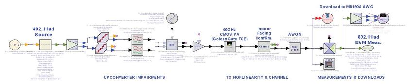
Why 60 GHz?
              Table 1 gives examples of the demand for Gigabit data rates over wireless connections for a
              range of consumer applications. Data capacity is ultimately tied to modulation bandwidth, so the
              extreme gigabit data-rates required for uncompressed high-definition multimedia transmissions
              must be accommodated, including known futures such as 2048 x 1080 and 4096 x 2160 (Digital
              Cinema) or 3D. Such data rates demand large spectrum allocation, and simplicity of high-volume
              manufacturing demands that this spectrum bandwidth should be a small percentage of the
              transmission frequency. The global unlicensed band that already exists at around 60 GHz, where
              multi-GHz modulation bandwidths are practical, meets the requirement.

              The unlicensed frequency allocations at around 60 GHz in each region do not match exactly, but
              there is substantial overlap; at least 3.5 GHz of contiguous spectrum is available in all regions that
              have allocated spectrum. Unlike the 2.4 GHz and 5 GHz unlicensed bands, the 60 GHz area is
              also relatively uncongested.

              Transmission at 60 GHz covers less distance for a given power, mainly due to the increased
              free space path loss (loss over 1 m at 60 GHz is 68 dB, which is 21.6 dB worse than at 5 GHz),
              compounded by propagation losses through materials and human body shadowing (losses from a
              few dB to 30 dB+).

              The substantial RF absorption peak in the 60 GHz band due to a resonance of atmospheric
              oxygen molecules is often cited as a limitation on range in this band, but this absorption effect
              only starts to become significant at >100 m range, which is not really relevant to the low-power
              transmissions being discussed here.

              So low-power transmissions will not propagate very far, but this is considered an advantage. It
              reduces the likelihood of co-channel interference and increases the possible frequency re-use
              density. Another perceived advantage of limited range is the reduced opportunity for “theft” of
              protected content by eavesdropping on nearby transmissions. (In fact, 60 GHz was first proposed
              for battlefield communications just for this reason.)

              A further enabler for consumer devices operating in this frequency range is the emergence of
              low-cost microwave component fabrication technologies. High-yield, micron-geometry compo-
              nents make 60 GHz devices and subsystems a commercial reality for consumer technology today,
              where only a few years ago they would have been unthinkable. Chips using CMOS, InP and SiGe
              IC technologies will be used extensively in 60 GHz wireless LAN devices.

              High path loss can be mitigated by increasing antenna gain. The small geometries required
              at 60 GHz permit the use of fabrication techniques such as Low-Temperature Co-fired Ceramic
              (LTCC) and thermoplastic substrates to create suitable, physically small, high-gain directional
              antennas.

              Multiple-antenna configurations using beam-steering are an optional feature of the specifcations.
              Beam-steering can be employed to circumnavigate minor obstacles like people moving around a
              room or a piece of furniture blocking line-of-sight transmission, but longer free-space distances
              (e.g. > 10 m) and more substantial obstructions (e.g. walls, doors, etc.) will prevent transmission.
              It would be unlikely, for example, for a media server in one room to be able to reliably transmit
              HD video directly to a display in another.

                                     3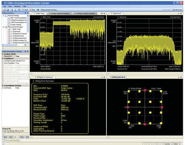
Regulatory Overview
                                               Since 1994, when the US Federal Communications Commission (FCC) first proposed to
                                               establish an unlicensed band at 59-64 GHz, radio regulatory organizations around the world
                                               have been legislating appropriate frequency allocations and modulation parameters to enable
                                               similar unlicensed bands in their respective jurisdictions.

                                               At the time of writing, the US and Canada, the European Union, Japan, South Korea, Australia
                                               and China have all finalized and approved an unlicensed spectrum allocation in the 60 GHz
                                               region. The situation is summarized in Figure 2.

                                                                       Spectrum Mask

                                                        U.S. and Canada (57.05 GHz – 64.00 GHz)

                                                                         European Union (57.00 GHz – 66.00 GHz)

                                                          South Korea (57.00 GHz – 64.00 GHz)

                                                                              Japan (57.00 GHz – 66.00 GHz)

                                                                       Australia (59.40 GHz – 62.90 GHz)

                                                                              China (59.00 GHz – 64.00 GHz)

                                        Channel 1                        Channel 2                         Channel 3                    Channel 4
              57.00 GHz
                          57.24 GHz

                                                           59.40 GHz

                                                                                            61.56 GHz

                                                                                                                          63.72 GHz

                                                                                                                                                        65.88 GHz
                                                                                                                                                        66.00 GHz
                                      F c = 58.32 GHz                  F c = 60.48 GHz                  F c = 62.64 GHz               F c = 64.80 GHz

                                               Figure 2. 60 GHz Band Channel Plan and Frequency Allocations by Region

                                               Figure 2 also documents the channelization of the 57-66 GHz band that has emerged by
                                               consensus from technical specification development work in the IEEE, Ecma, the WirelessHD
                                               Consortium and the Wireless Gigabit Alliance. In November 2011 this channelization and a
                                               corresponding spectrum mask for the occupying signal was approved by ITU-R WP 5A for
                                               global standardization.

                                               The ITU-R recommended channelization comprises four channels, each 2.16 GHz wide,
                                               centered on 58.32 GHz, 60.48 GHz, 62.64 GHz and 64.80 GHz respectively. As Figure 2
                                               illustrates, not all channels are available in all countries. Channel 2, which is globally available,
                                               is therefore the default channel for equipment operating in this frequency band.

                                                                         4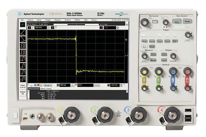
Regulatory Overview
                                     The spectrum mask, shown to scale at the top of Figure 2, is expressed in decibels relative
                                     to the signal level at the band center (dBr); as shown more precisely in Figure 3.

                                                                                    0 dBr

                                                                                            -20 dBr

                                                                                                                   -25 dBr

                                                                                                                             -30 dBr

        -3.06   -2.7   -2.2   -1.8        -1.2 -0.94                fC          +0.94 +1.2            +1.8      +2.7    +3.06
                                                             Frequency (GHz)

                                     Figure 3. IEEE 802.11ad Spectrum Mask

                                     The spectrum mask in Figure 3 is the final version, as defined by 802.11ad. This super-
                                     sedes the more stringent mask that was approved by ITU WPA5. This mask is significantly
                                     different to the masks specified at lower frequencies. The breakpoints at -20 dBr have
                                     been pushed out slightly to accommodate both OFDM and Single Carrier modulations,
                                     and the adjacent channel requirements have been considerably relaxed, specifically to
                                     ease the circuit design challenges at 60 GHz by permitting higher levels of out of band
                                     distortion.

                                     The maximum permitted transmitter power varies by country, but in general +10 dBm can
                                     be taken as a practical limit.

                                                         5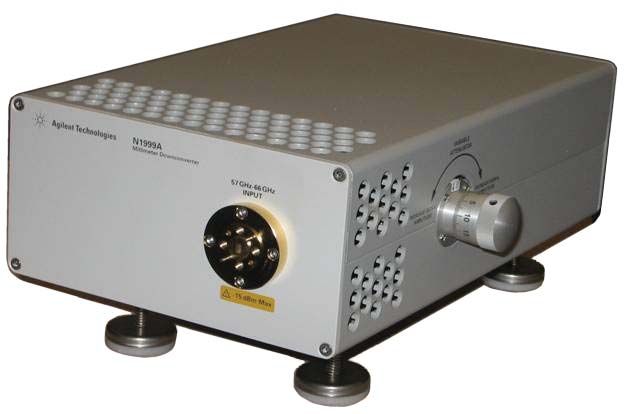
A History of Specifications Targeting the 60GHz Band
IEEE 802.15.3c            The IEEE 802.15 Working Group develops standards for Wireless Personal Area Networks
(2005 – 2009)             (WPAN).

                          Within the IEEE 802.15 working group, Task Group 3 (TG3) was tasked with developing
                          high-rate (>20 Mbps) WPANs, and the outcome was IEEE 802.15.3-2003. Following
                          the completion of that specification Task Group 3c (TG3c) was formed, in March 2005, to
                          develop a millimeter-wave-based alternative physical layer (PHY) for the IEEE 802.15.3-
                          2003 standard and the result was IEEE 802.15.3c-2009.

                          IEEE 802.15.3c-2009 endeavours to address a wide range of applications by having three
                          distinct PHYs; a “single carrier” (SC) mode, a “high speed interface” (HSI) mode and an
                          “audio/visual” (AV) mode, all of which are significantly architecturally different.
                          The single carrier SC and HSI modes use PSK/QAM modulation and so can trade reduced
                          peak data rates for improved peak/average power ratios when compared with the OFDM-
                          based AV mode. The SC/HSI modes are thus considered to be a better fit to the power
                          limitations of the battery operated equipment that typically participates in a PAN (phones,
                          cameras, MP3 players etc.).

                          The OFDM-based AV mode is better able to deal with multipath distortions and so can
                          offer greater range than SC-based modes, albeit at the expense of power consumption.
                          In this specification, the AV mode is exactly the same as the HRP PHY in WirelessHD 1.0
                          (although the MAC layers are different between the two specifications).

                          At the time of writing, no commercially available equipment employs the IEEE 802.15.3c
                          standard.

                                              6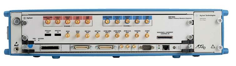
A History of Specifications Targeting the 60GHz Band
WirelessHD®               In April 2006, the WirelessHD Consortium was founded to develop and promote an
(2006 – present)          industry-standard next-generation wireless digital interface specification for consumer
                          electronics, PC and portable products.

                          The consortium was founded by SiBEAM Inc. in collaboration with LG Electronics
                          Inc., Panasonic Corporation, NEC Corporation, Samsung Electronics, Co., Ltd, Sony
                          Corporation, and Toshiba Corporation. Subsequently this core group of founding com-
                          panies was expanded to include Intel Corporation (Jan 2008), Broadcom Corporation
                          (August 2008) and Royal Philips Electronics N.V. (September 2009). These original ten
                          companies had elevated status within the consortium as Promoter Companies and the
                          membership was augmented by several Adopter Companies. The WirelessHD Consortium
                          is still in existence and actively promoting WirelessHD technology, but the roster of
                          Promoter Companies has evolved and the Adopter membership has declined in recent
                          years, reflecting a general shift of focus in the industry towards 802.11ad.

                          The WirelessHD specification defines an architecture and technology for short-range (10 m)
                          wireless interchange of high-definition multimedia data between audio-visual devices over
                          an ad-hoc network in the 60GHz unlicensed band.

                          Version 1.0 of the WirelessHD specification was published in January 2008, followed by
                          version 1.1 in April 2010.

                          The multimedia optimised protocol is underpinned by a physical layer capable of high
                          speed data transmission; originally (v1.0) at rates up to 3.81Gbps, laterly (v1.1) at rates
                          up to 7.138 Gbps, and, in principle, up to 4 x 7.138 = 28.552 Gbps if using 4 x 4 spatial
                          multiplexing (MIMO) .

                          The ad-hoc network is established and managed through bi-directional protocol exchang-
                          es over the Low Rate PHY (LRP) while bulk data transfer takes place over the unidirec-
                          tional Medium Rate PHY (MRP) or High Rate PHY (HRP). All three PHYs employ beam-
                          steering techniques for Non Line Of Sight (NLOS) operation.

                          LRP, MRP and HRP transmissions share a common frequency channel using Time Division
                          Multiple Access (TDMA) techniques managed by the protocol layer. LRP, MRP and HRP
                          are all RF burst transmissions starting with a synchronization preamble followed by packet-
                          structured OFDM modulated data.

                                              7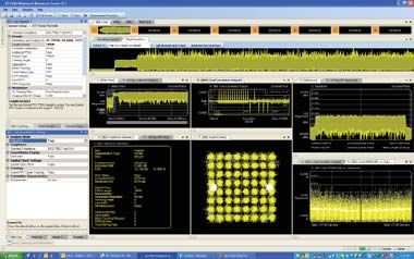
A History of Specifications Targeting the 60GHz Band
ECMA-387 and ISO/IEC 13156                     Ecma International is a not-for-profit industry association based in Geneva that was
(2008 – present)                               established in 1961 for the purpose of developing and publishing standards and technical
                                               reports in the areas of Information and Communication Technology (ICT) and Consumer
                                               Electronics (CE).

                                               In December 2008 Ecma published the first edition of the ECMA-387 High Rate 60 GHz
                                               PHY, MAC and HDMI PAL Standard for short range unlicensed communications. This
                                               document subsequently passed through the ISO/IEC fast-track approval procedure to
                                               become ISO/IEC 13156:2009.

                                               More recently, in December 2010, Ecma published a second edition of ECMA-387,
                                               which also passed through the ISO/IEC fast-track approval procedure to become ISO/IEC
                                               13156:2011.

                                               At the time of writing, no commercially available equipment employs the ECMA-387 stan-
                                               dard or its ISO/IEC equivalent.

NGmS                                           In October 2007, representatives of leading wireless and consumer electronics companies
(2007 – 2009)                                  from around the World met to consider a proposal to develop a unified “Next Generation
                                               millimeter-wave Specification” (NGmS)1.

                                               Some of the participants in that meeting went on to collaborate in identifying and docu-
                                               menting market requirements, and creating an early draft specification. The NGmS group
                                               was disbanded in 2009 with the formation of the Wireless Gigabit Alliance and the work
                                               of the NGmS was carried forward by the new organization.

Wireless Gigabit Alliance/                     On April 1, 2009, the Wireless Gigabit Alliance (WGA) was incorporated with the intent to
WiGig™                                         develop specifications that define transmission of audio, video, and data in the millimeter
(2009 – 2013)                                  wave frequency band operating in both Line Of Sight (LOS) and Non-Line Of Sight (NLOS)
                                               environments. The WGA also own the trademark and brand “WiGig” to describe this
                                               technology.

                                               Version 1.0 of the WGA MAC and PHY Specification was published under the “WiGig”
                                               brand in February 2010 and this was followed by version 1.1 in April 2011. A proposal
                                               based on the WGA MAC and PHY version 1.0 Specification was contributed to IEEE
                                               802.11 Task Group ‘ad’ (TGad) as a complete proposal specification (IEEE document
                                               10/433r2) and was approved as TGad D0.1 on 20 May 2010.

                                               Since then, up until the eventual publication of IEEE 802.11ad-2012 in December 2012,
                                               the WGA and IEEE maintained alignment between the evolving WGA and IEEE MAC and
                                               PHY specifications, so that the published IEEE 802.11ad and WiGig v1.2 MAC/PHY final
                                               specifications are essentially identical.

                                               In December 2012, the Wi-Fi Alliance and WGA executed a Memorandum of
                                               Understanding (MOU) outlining their plans to consolidate activity in Wi-Fi Alliance, this
                                               intent was confirmed by a finalized agreement in March 2013 to consolidate WiGig tech-
                                               nology and certification development in Wi-Fi Alliance. This transfer should be complete
                                               by June 2013 and all further development of this technology, particularly the protocol
1. http://techon.nikkeibp.co.jp/article/HON-   adaptations, will be conducted by Wi-Fi Alliance in collaboration with other organizations
SHI/20071219/144407                            such as VESA, PCI-SIG and USB-IF.

                                                                   8
A History of Specifications Targeting the 60GHz Band
IEEE 802.11.ad            The IEEE 802.11 Working Group develops standards for Wireless Local Area Networks
(2009 – 2012)             (WLAN).

                          Within the IEEE 802.11 working group, Task Group ‘ad’ (TGad) was tasked with defining
                          modifications to the 802.11 MAC and PHY to enable operation in the 60 GHz frequency
                          band capable of Very High Throughput (VHT), where VHT was defined as capable of a
                          maximum throughput of at least 1 Gbps.

                          The Project Activation Request was approved in December 2008 and the working group
                          was formed in January 2009.

                          In response to the TGad call for proposals (IEEE document 09/1206r0) issued in November
                          2009, a proposal based on the WGA MAC and PHY version 1.0 Specification was con-
                          tributed to IEEE 802.11 Task Group ‘ad’ (TGad) as a complete proposal specification (IEEE
                          document 10/433r2) and was approved as TGad D0.1 on 20 May 2010. As required by
                          the PAR, the 802.11ad specification defines a backwards-compatible extension to the IEEE
                          802.11-2012 specification that extends the MAC and PHY definitions as necessary to sup-
                          port short-range (1m - 10m) wireless interchange of data between devices over an ad-hoc
                          network at data rates up to 6.75 Gbps in the 60GHz unlicensed band. It also supports ses-
                          sion switching between the 2.4GHz, 5GHz and 60GHz bands.

                          The ad-hoc network is established and managed through bi-directional protocol exchang-
                          es using a low data-rate control channel (MCS 0) while bulk data transfer takes place
                          over an appropriate higher-rate mode (MCS1..31). The higher rate modes employ beam-
                          steering techniques for NLOS operation.

                          802.11ad uses RF burst transmissions that start with a synchronization preamble (com-
                          mon to all modes) followed by header and payload data. The preamble is always single-
                          carrier modulation, the header and data may use single-carrier (SC) or OFDM modulation
                          depending on the target bit rate.

                          The final IEEE 802.11ad-2012 specification was published, on schedule, in December
                          2012 and Task Group TGad held its final meeting in March 2013.

Looking forward           At the time of writing (May 2013), it seems highly likely that IEEE 802.11ad will become
                          the most widely deployed 60 GHz technology, however the WirelessHD technology that
                          pioneered the commercialization of this band may endure in some high-performance niche
                          applications.

                          In the rest of this document we will refer to IEEE 802.11ad only, but (at the PHY level) this
                          can be taken as a synonym for WiGig 1.2.

                                              9
Overview of IEEE 802.11ad-2012 PHY
Introduction                        This section provides a brief summary of the mmWave PHY layer defined in clause 21 of
                                    the IEEE 802.11ad-2012 amendment to IEEE Std. 802.11™-2012. To maintain generality
                                    in the specification text, and to simplify functional descriptions in future, the IEEE has
                                    introduced new terminology to identify the higher performance PHYs;

                                    • VHT, which is short for very high throughput, is any frequency band that has a
                                      starting frequency below 6 GHz excluding the 2.4 GHz band.
                                    • DMG, which is short for directional multi-gigabit, pertains to operation in any frequency
                                      band that contains a channel with a channel starting frequency above 45 GHz.

                                    These terms replace the previous, more frequency-specific terms LB (Low Band at
                                    2.4GHz), HB (High Band at 5GHz), and UB (Ultra Band at 60GHz).

                                    So, using the new terminology, clause 21 of IEEE 802.11ad-2012 defines the DMG PHY,
                                    which is normally deployed in the “60 GHz” band from 57 GHz to 66 GHz; subject to the
                                    regional variations documented in Figure 2.

Packet structure                    The IEEE 802.11ad-2012 DMG PHY supports three distinct modulation methods:
                                    • Spread-spectrum modulation; the Control PHY.
                                    • Single carrier (SC) modulation; the Single Carrier PHY and the Low Power Single
                                      Carrier PHY.
                                    • Orthogonal Frequency Division Multiplex (OFDM) modulation; the OFDM PHY.
                                    Each PHY type has a distinct purpose and packet structure, shown in Figure 4, but care
                                    has been taken to align the packet structures, and in particular the preambles, to simplify
                                    signal acquisition, processing and PHY type identification in the receiver.

                                                                  π/2-DBPSK

                   Control                        Preamble                                                      Beamforming
                                                                                   Header          Data
                                                 STF                      CEF                                     Training

                                                π/2-BPSK                         π/2-BPSK/QPSK/QAM16

                                     Preamble                                                                   Beamforming
                   Single Carrier                             Header                        Data
                                    STF         CEF                                                               Training

                                                π/2-BPSK                              π/2-BPSK/QPSK

                   Low Power         Preamble                                                                   Beamforming
                   Single Carrier                             Header                        Data
                                    STF         CEF                                                               Training

                                      π/2-BPSK               QPSK-OFDM        SQPSK/QPSK/QAM16/QAM64-OFDM

                                     Preamble                                                                   Beamforming
                   OFDM                                       Header                        Data
                                    STF         CEF                                                               Training

                                    Figure 4. Packet structures for each of the three modulation types

                                                        10
Overview of IEEE 802.11ad-2012 PHY
Packet structure Preamble
The three packet types share an essentially common preamble structure comprising a
Short Training Field (STF) followed by a Channel Estimation Field (CEF). These fields are
constructed from p/2-BPSK modulated repeating Golay sequences that are described in
more detail below.
Gb128 Gb128 Gb128 -Gb128 -Ga128 -Gb128 -Ga128 Gb128 -Ga128 -Gb128 Ga128 -Gb128 -Ga128 -Gb128
CPHY Short Training Field (STF) 6400 Tc SC Channel Estimation Field (CEF) 1152 Tc
Ga128 Ga128 Ga128 -Ga128 -Gb128 -Ga128 Gb128 -Ga128 -Gb128 Ga128 -Gb128 -Ga128 -Gb128
Short Training Field (STF) 2176 Tc SC Channel Estimation Field (CEF) 1152 Tc
Ga128 Ga128 Ga128 -Ga128 -Gb128 Ga128 -Gb128 -Ga128 -Gb128 -Ga128 Gb128 -Ga128 -Gb128
Short Training Field (STF) 2176 Tc OFDM Channel Estimation Field (CEF) 1152 Tc
Figure 5. Preamble Variants Expressed in terms of Ga128 and Gb128 sequences
Figure 5 shows the structure of the three different preamble types in more detail, illustrating
that the basic building blocks are the Golay complementary sequences Ga128 and Gb128.
11Overview of IEEE 802.11ad-2012 PHY
Packet structure Golay complementary sequences
Golay complementary sequences are sequences of bipolar symbols (±1) that have been
mathematically constructed to have very specific autocorrelation properties. The ‘a’ and
‘b’ indicate that the Ga128 and Gb128 sequences form a complementary pair and the suffix
indicates the sequence length. 802.11ad also uses Ga32 , Ga64 and Gb64 sequences.
The mathematics behind the sequence constructions is beyond the scope of this note, but
three important attributes of these sequences are,
1. The autocorrelation of each sequence has low false peaks and low DC content under
/2 rotation
2. The sum of the very good but imperfect autocorrelation functions of the Ga and Gb
sequences is perfect (the false peaks cancel exactly)
3. The Ga and Gb autocorrelations can be performed in parallel using a single, hardware
efficient (and therefore fast) correlator.
A suitable fast correlator architecture is illustrated generically in Figure 6.
W1 W2 Wk
ra1 (n) ra2 (n) rak-1 (n) rak(n)
r(n)
rb1 (n) rb2 (n) rbk-1 (n) rbk(n)
D1 D2 Dk
Figure 6. Fast correlator architecture
Notice that the correlator performs both ‘a’ and ‘b’ correlations in parallel. It has a single
input, but two outputs, one for the ‘a’ sequence and one for the ‘b’ sequence. If the
Ga128/Gb128 version of this correlator receives a 802.11ad preamble short training field
(STF) at the input r(n), the ra7(n) output will produce a sequence of positive going cor-
relation spikes for an SCPHY or OFDMPHY STF, whereas positive correlation spikes on the
rb7(n) output signal the arrival of a CPHY STF.
In both cases, The periodicity of the spikes gives a direct measure of the reference
sample rate, the spike amplitude can drive an AGC function, and a negative spike on the
ra7(n) output signals the end of the STF. The complementary nature of the ‘a’ and ‘b’
sequences is not used in the STF (other than the benefit of having a correlator that can
perform both correlations in parallel and thereby signal whether or not a CPHY packet is
being received).
12Overview of IEEE 802.11ad-2012 PHY
Packet structure Golay complementary sequences
The construction of the CEF is more mathematically sophisticated and does take advan-
tage of the complementary property; the first four and second four Ga128/Gb128 comple-
mentary sequences are logically grouped into 512-symbol groups labelled Gu512 and Gv512
as illustrated in Figure 7.
Gb128 Gb128 -Gb128 -Ga128 Gu512 Gv512 Gv128
CPHY Short Training Field (STF) 6400 Tc SC Channel Estimation Field (CEF) 1152 Tc
Ga128 Ga128 Ga128 -Ga128 Gu512 Gv512 Gv128
Short Training Field (STF) 2176 Tc SC Channel Estimation Field (CEF) 1152 Tc
Ga128 Ga128 Ga128 -Ga128 Gv512 Gu512 Gv128
Short Training Field (STF) 2176 Tc OFDM Channel Estimation Field (CEF) 1152 Tc
Figure 7. The preambles redrawn to show the CEF structure
The Gu512 and Gv512 blocks can be used to perform two independent channel estimations
and the results can be summed to give a composite estimate. The basic principle behind
the structure of the channel estimation fields is illustrated in Figure 8.
a h(t) Golay R ( a ) = a a h(t)
a H correlator
Σ output = R ( a ) + R ( b)
= a a h(t) + b b h(t)
b h(t) Golay R ( b ) = b b h(t)
b H = ( a a + b b ) h(t)
correlator
= δ ( t ) h(t)
= h(t)
Figure 8. The principle behind the channel estimation field
We have two time sequences, ‘a’ and ‘b’. If we pass sequence ‘a’ through the channel H
we convolve the sequence and the channel impulse response, h(t).
If we pass the received signal through a Golay correlator for the known input sequence
then we get the autocorrelation of sequence ‘a’ convolved with the channel impulse
response.
If sequence ‘b’ is processed similarly, we get the autocorrelation of sequence ‘b’ convolved
with the same channel impulse response.
If we add the two results together then, because sequences ‘a’ and ‘b’ are Golay comple-
mentary sequences, the sum of their autocorrelations is an impulse response and we are
left with the channel response, h(t).
13Overview of IEEE 802.11ad-2012 PHY
Packet structure Golay complementary sequences
For satisfactory channel estimation we need to use a longer sequence than 128 samples.
Therefore, in the Gu512 block for example, the ‘a’ sequence is provided by the concat-
enation of –Gb128 and –Ga128 , with the concatenation of Gb128 and –Ga128 providing the
complementary ‘b’ sequence. There is a similar complementary pairing in the Gv512 block.
Also, to eliminate channel estimation errors caused by signal dispersion through multipath
channels, the CEF is always preceded by a -Ga128 sequence as the last sequence in the
STF and similarly followed by a -Gb128 sequence (annotated as Gv128). The polarities of
these sequences, taken together with those in the Gu and Gv blocks, are defined in a way
that allows dispersive errors, such as Ga128 leaking into Gb128, to be cancelled when the
‘a’ and ‘b’ correlator outputs are combined.
Also by comparing Figure 5 and Figure 7, we can see that the Gu512 and Gv512 group
definitions are the same in all three modes, but they are time reversed for the OFDM PHY
compared with the CPHY and SCPHY.
The time order of Gu512 and Gv512 is unimportant for channel estimation since each pro-
duces an independent estimate, but the reversal of these fields is used to signal that the
subsequent payload is OFDM rather than Single Carrier modulated.
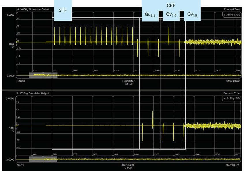
Figure 9. the Ga128 and Gb128 correlator outputs for the SCPHY preamble of an ideal signal.
Looking at Figure 9, for the STF field we can see the correlation spike for each of the 16
repetitions of Ga128 followed by a single negative spike for the terminating -Ga128. This is
followed by the sequence of 9 pulses across Ga128 and Gb128 that constitute the CEF.
14Overview of IEEE 802.11ad-2012 PHY
Packet structure Header
In all cases the preamble is followed by a header field that conveys information about the
rest of the packet. Most importantly it signals the Modulation and Coding Scheme (MCS)
being used for the payload part of the packet.
The information encoded in the header is very similar for Single Carrier and OFDM pack-
ets, except that the OFDM header defines a couple of additional OFDM-specific fields; the
Tone Pairing Type and Dynamic Tone Pairing (DTP) Indicator flags.
The Control packet header is an abbreviated but otherwise consistent version of the stan-
dard header. The header field structures are illustrated in Figure 10.
Control
1 4 10 bits 1 5 bits 1 2 16 bits
Reserved (diff detector init)
Scrambler Initialization
Length
Packet type
Training Length
Turnaround
Reserved bits
HCS
Single Carrier
7 bits 5 bits 18 bits 1 1 5 bits 1 1 4 bits 1 4 bits 16 bits
Scrambler Initialization
MCS
Length
Additional PPDU
Packet type
Training Length
Aggregation
Beam Tracking Request
Last RSSI
Turnaround
Reserved
HCS
OFDM
7 bits 5 bits 18 bits 1 1 5 bits 1 1 1 1 4 bits 1 2 16 bits
Scrambler Initialization
MCS
Length
Additional PPDU
Packet type
Training Length
Aggregation
Beam Tracking Request
Tone Pairing Type
DTP Indicator
Last RSSI
Turnaround
Reserved
HCS
Figure 10. Header field structures
Some of the more important fields are,
• Scrambler Initialization: This field seeds the scrambler which is applied to the remainder
of the header and the payload for data whitening purposes.
• MCS: This field indicates the modulation and coding scheme employed in the payload
part of the packet.
• Length: This field indicates the number of octets of data in the payload.
• Training Length: This field indicates the length of the optional beam forming training
field at the end of the packet.
• Packet Type: This flag indicates whether the optional beam forming training field is
configured for transmitter or receiver training.
• HCS: This is a CRC-32 checksum over the header bits.
Payload
The packet payload content is a stream of octets. As mentioned, the header Length field
quantifies the useful content of the payload. Prior to encoding, the payload data, depend-
ing on the chosen length, may be extended by a small amount, using “stuffing bits”, so
that the encoding process will produce a whole number of modulation blocks or symbols.
These dummy data are discarded by the decoding process.
15Overview of IEEE 802.11ad-2012 PHY
Modulation and coding The specification tabulates 32 different modulation and coding schemes. However, as we
schemes have seen in the preceeding paragraphs, there are just a few variations in the modulation
and encoding of the preamble and header fields across all 32 MCS.
The packet type, and therefore the modulation of the header field is signalled by modest
variations in the preamble’s fields; the use of Gb128 rather than Ga128 sequences in the STF
signals a Control packet, while the ordering of the Gu512 and Gv512 fields in the CEF signals
whether this is an SC or OFDM packet.
Thus we can quickly simplify the picture by dividing the MCS list into four basic classifications.
Table 2. Summary of P802.11ad Modulation and Coding Schemes (MCS)
Control (CPHY)
Coding Modulation Raw Bit Rate
Shortened 3/4 LDPC, p/2-DBPSK 27.5 Mbps
32x Spreading
Single Carrier (SCPHY)
Coding Modulation Raw Bit Rate
1/2 LDPC, 2x repetition p/2-BPSK, 385 Mbps
1/2 LDPC, p/2-QPSK, to
5/8 LDPC p/2-16QAM 4620 Mbps
3/4 LDPC
13/16 LDPC
Orthogonal Frequency Division Multiplex (OFDMPHY)
Coding Modulation Raw Bit Rate
1/2 LDPC, OFDM-SQPSK 693 Mbps
5/8 LDPC OFDM-QPSK (DCM) to
3/4 LDPC OFDM-16QAM 6756.75 Mbps
13/16 LDPC OFDM-64QAM
Low-Power Single Carrier (LPSCPHY)
Coding Modulation Raw Bit Rate
RS(224,208) + p/2-BPSK, 625.6 Mbps
Block p/2-QPSK to
Code(16/12/9/8,8) 2503 Mbps
Table 2 illustrates the underlying order and purpose in such an apparently large choice of MCS.
It is clearly important, for the reliable establishment and maintenance of connectivity, that
the control channel should be as robust as possible. The purpose of the control PHY, and
the reasons for its emphasis on reliability over raw speed are considered evident.
It is perhaps less clear why so many MCS are required.
Given the anticipated diversity of device type that will want to support 802.11ad there are
persuasive arguments for and against both OFDM and Single Carrier based modulations,
and for seriously constrained devices there is a further argument in favour of trading the
strength of LDPC-based error correction for further power savings.
Within each of the SC, OFDM and LPSC categories, the specific MCS selects a different
pairing of error protection coding and modulation depth, which taken together provide the
user with a logical progression of link quality versus throughput operating points.
16Overview of IEEE 802.11ad-2012 PHY
Modulation and coding Control PHY
schemes Modulation and Coding Scheme 0 (MCS0) is by far the most robustly coded (and conse-
quently, lowest throughput) mode. Its purpose is exclusively to transmit control channel
messages and it is referred to as the Control PHY (CPHY). Support for MCS0 is mandatory.
The CPHY robustness is evident from its use of differential encoding, code spreading
and BPSK modulation. Differential encoding eliminates the need for carrier tracking, 32x
spreading contributes a theoretical 15 dB gain to the link budget, and BPSK is, of course,
very noise tolerant.
A Ga32 Golay complementary code is used as the spreading code, so we can see the
result of the despreading process directly by looking at the Ga32 correlator output.
LDPC differential 32x
scrambler
(x 7+x 4+1) encoder encoding spreading
(shortened 3/4)
p/2-BPSK spectrum
up conversion
modulation shaping
Figure 11. Summary block diagram of CPHY encoding and modulation steps
Single carrier PHY
Modulation and Coding Schemes 1 through 12 (MCS1 – MCS12) employ single-carrier
modulation; specifically BPSK, QPSK or 16-QAM modulation of a (suppressed) carrier at
the channel center frequency, at a fixed symbol rate of 1.76 Gsym/s. All 12 modes are
essentially identical in their channel encoding steps, they differ only in the choice of error
protection ratio and modulation density, to allow the appropriate tradeoff between through-
put and robustness to be determined operationally (by mode selection). These 12 modes
are collectively referred to as the Single Carrier PHY (SCPHY). Support for modes MCS1 to
MCS4 is mandatory, to ensure that all compliant devices are capable of data interchange
at rates in excess of 1Gbps as required by the original TGad PAR.
The Low-Density Parity Check (LDPC) error correcting coding technique that is common
to the CPHY, SCPHY and OFDMPHY MCS is based on a common codeword length of 672
bits each carrying either 336, 504, 420 or 546 payload bits to achieve rate 1/2, 3/4, 5/8
or 13/16 as required.
LDPC 2X data blocking
scrambler
(x 7+x 4+1) encoder repetition guard interval
(1/2, 3/4, 5/8, 13/16) (header only) (448 blocks + 64 GI = 512)
p/2-BPSK
p/2-QPSK spectrum
up conversion
p/2-16QAM shaping
modulation
Figure 12. Summary block diagram of SCPHY encoding and modulation steps
17Overview of IEEE 802.11ad-2012 PHY
Modulation and coding Single carrier PHY
schemes The LDPC code employs a Cyclic Shifted Identity (CSI) construction based on a submatrix
size of 42 and was designed to permit very efficient encoding using back substitution, and
decoding using either fully parallel or layered decoding techniques.
512 symbol modulation block
Ga64 guard 448 symbols
interval
Figure 13. SC PHY payload modulation block
The data blocking and guard interval divides the modulation symbols into groups of 448
symbols interspersed with 64 symbol “Golay sequence guard intervals” (GI) that provide
the receiver with a periodic known reference signal to assist with gain and phase tracking.
The 64 symbol guard interval is a Ga64 Golay sequence and its periodic occurrence can be
confirmed by examining the output of the Ga64 correlator.
The modulation is very conventional single-carrier modulation which is p/2 rotated to mini-
mise the peak to average power ratio (PAPR) of the BPSK modulation (the GI’s are always
BPSK modulated) and to allow equivalent GMSK modulation.
Spectrum shaping is mandated but the details are not specified, to permit some design
freedom.
OFDM PHY
Modulation and Coding Schemes 13 through 24 (MCS13 – MCS24) employ multi-carrier
modulation; specifically Orthogonal Frequency Division Multiplex (OFDM) modulation,
which can provide higher modulation densities and hence higher data throughput than the
single carrier modes. As for the single carrier modes, all 12 OFDM modes have near iden-
tical encoding, varying only in choice of error protection ratio and the depth of modulation
applied to the OFDM data carriers, again to provide operational control over the robust-
ness/throughput trade-off. Support for OFDM modulation is not required by the specifica-
tion, but if it is implemented, then MCS13 to MCS16 are mandatory to ensure some level
of interoperability between OFDM-capable devices.
LDPC 3X carrier pilot and
scrambler DC null
(x 7+x 4+1) encoder repetition mapping
(1/2, 3/4, 5/8, 13/16) (header only) (QPSK, QAM16, QAM64) insertion
cyclic window
IFFT up conversion
(512 points) prefix functioning
(25% repetition) (transition smoothing)
Figure 14. Summary block diagram of OFDMPHY encoding and modulation steps
18Overview of IEEE 802.11ad-2012 PHY
Modulation and coding OFDM PHY
schemes With regard to the choice of single carrier or OFDM modulation; the generally accepted
reason for favouring one over the other is the relative importance, in a given application, of
power consumption (i.e. maximizing battery life) compared with maximizing data throughput.
OFDM modulation has a large and often unpredictable peak to average power ratio (PAPR)
which is challenging for a linear power amplifier to accommodate efficiently. On the other
hand, single-carrier modulation typically has a low or even unity PAPR, which lends itself to
very efficient and battery-friendly power amplification.
Conversely, OFDM has a significant advantage over single carrier modulation in terms of
energy per bit and is particularly robust in the presence of multi-path distortion, both of
which give it the edge in the data throughput achievable for a given channel.
That said, such distinctions are shifting and eroding all the time as the technologies develop.
The LDPC encoding is identical to that used in the single carrier modes.
The OFDM is based on a 512-point FFT with 336 active data carriers, and 16 fixed pilot
tones. The carriers at DC and on either side of DC are nulled to avoid any issues with car-
rier feed-through and the cyclic prefix is fixed at 25% of the symbol period.
The individual OFDM carrier modulation may be SQPSK, QPSK, QAM16 or QAM64.
SQPSK is Spread QPSK, in this mode, the OFDM carriers are paired and the same data is
modulated onto two carriers maximally separated in frequency to improve the modulation’s
robustness in the presence of selective frequency fading. The idea is that if one carrier is
lost to a null the other is unlikely to be affected at the same time. The pairing of tones is
normally static, but there is an option to pair them dynamically according to channel condi-
tions, which has been shown to provide additional robustness.
MCS15, 16 and 17 are described as using QPSK but in fact use Dual Carrier Modulation,
which is QPSK-like in its performance, but is, nonetheless, a different technique.
Dual carrier modulation also uses frequency diversity to mitigate selective fading, but it
does so in a more subtle way than SQPSK.
In DCM, four bits of payload data are assigned to two subcarriers, which means that, in
terms of “bits per subcarrier” it is similar to QPSK. However, in DCM the state of all four
bits determines the amplitude and phase state of both subcarriers. Put another way, both
subcarriers convey information about all four bits. At the receiver, information from both
subcarriers can be combined to recover the original 4 bits.
The QAM16 and QAM64 modulations are very conventional.
19Overview of IEEE 802.11ad-2012 PHY
Modulation and coding Low power single carrier PHY
schemes Finally, consider Modulation and Coding Schemes 25 to 31 (MCS25 – MCS31). This
distinctly different group of modes also employs single-carrier modulation, specifically
to minimize power consumption, but goes beyond that to specify an alternative channel
encoding scheme that replaces LDPC with a combination of Reed-Solomon and Hamming
block codes.
scrambler RS(224, 208) (N, 8) block 7 x 8 block
(x 7+x 4+1) encoder encoder interleaver
(N=16, 12, 9, 8)
symbol blocks p/2-BPSK
or spectrum
and p/2-QPSK up conversion
shaping
guard insertion modulation
Figure 15. Summary block diagram of LPSCPHY encoding and modulation steps
Again the motivation is to minimize power consumption. In the current state of the art, LDPC
encoding/decoding consumes significantly more IC real-estate and hence power than a
Reed-Solomon based solution, but that power saving comes at the expense of less robust
error correction.
Nonetheless, small battery-powered devices could benefit from the extra power savings and
so these MCS have been included and collectively constitute the Low Power Single Carrier
PHY (LPSC-PHY). Although the LPSC PHY payload encoding is significantly different from the
other modes, the LPSC PHY packets use the common preamble to facilitate coexistence with
devices that do not support these MCS. MCS25 to MCS31 are optional, but a device that
implements the LPSC PHY modes will still have to implement at least MCS0 to MCS4.
512 symbol modulation block
Ga64 guard 56 56 56 56 56 56 56
interval symbols symbols symbols symbols symbols symbols symbols
G8 G8 G8 G8 G8 G8 G8
Figure 16. UPC PHY payload modulation block
The symbol blocking and guard interval divides the modulation symbols into groups of
448 symbols interspersed with 64 symbol GI in a manner compatible with the SCPHY.
However the 448 symbols are further deconstructed into 7 sub-groups of 56 data sym-
bols each postfixed with a “G8” guard interval comprising the first 8 symbols of a Ga64
sequence (7 x 64 = 448). Thus each LPSCPHY block carries 392 data symbols.
20Overview of IEEE 802.11ad-2012 PHY
Beamform training The optional optional beamforming training field is the same for all packet types. It, again,
comprises a pattern of modulated repeating Golay sequences, the details being determined
by the Training Length and Packet Type fields in the header.
Beam Management
The small physical size of an antenna at 60GHz, and the low-cost manufacturing techniques
available, make phased array antenna systems commercially feasable. Beamforming allows
a pair of devices to train their antenna systems to maximize transmission robustness.
Beamforming training is a bi-directional sequence of training frame transmissions that are
appended to each transmission type as shown in the figures above, and are used to shape
either or both transmit and receive antenna patterns in real time to account for local move-
ment and interuptions to line-of-sight communication. Either of the pair of devices can initi-
ate a “beam refinement transaction”, which is a set of beam refinement frames consisting of
beam refinement requests and responses. A beam refinement request can be either a trans-
mit beam refinement request or a receive beam refinement request or both. A beam refine-
ment transaction is complete when the device which initiated it determines that it does not
need further training and it has received a beam refinement frame with no training requests
from the other device of the pair (known as the responder).
2160 GHz PHY Testing
Component and system design and test at 60 GHz is a well-understood and established sci-
ence. Tools for mmWave circuit design and simulation, network analysis, signal analysis and
power measurement have been available for a number of years for use in applications such
as short-range radar and military communications. The major difference required by the new
commercial 60 GHz applications is the much wider modulation bandwidth, and hence the
different test solutions, required.
Agilent’s design simulation and stimulus and analysis solutions are described below.
W1915 SystemVue mmWave SystemVue is a system-level communications design environment that brings together physi-
WPAN baseband verification cal layer baseband algorithmic modelling, accurate RF modelling, standards-based reference
library IP, and direct interaction with test equipment. It is used early in the R&D lifecycle by system
architects, and follows both the RF and Baseband design paths into implementation, provid-
ing continuity for cross-domain verification.
W1915 mmWave WPAN Baseband Verification Library is a SystemVue add-on library that pro-
vides configurable IP references for 802.11ad and 802.15.3c wireless communications physical
layers operating at 60 GHz. It is used by designers to verify baseband algorithms, system perfor-
mance with faded and precisely impaired channels, and various RF components. Because of the
difficulty in making 60 GHz components and measurements, SystemVue simulations are able to
assist in these key ways:
• Validation of early RFIC and MMIC designs in Agilent GoldenGate and ADS, prior to
taping out a wafer.
• Economical system-level validation and high-fidelity early pre-compliance using simulations, so
that final hardware compliance testing can be performed more quickly, with greater confidence.
• Generation of consistent test vectors for simulation vs. hardware testing, using a direct
download to the Agilent M8190A AWG and measurement using the 81199A WWC soft-
ware. The W1915 library is interoperable with the 81199A and 89600 VSA applications.
Download to M8190A
Realistic 60 GHz TX/RX system impairments for hardware test
802.11ad
coded
TX/RX
BB source Upconverter 60 GHz PA Channel Receiver
• Test vector generation • Quantizer (12 b vs. 16 b) • Ideal PA model • Noise, fading • Downconversion
• Coding • Filtering • X-parameters • Multipath • Noise and filtering
• Std pre-compliance • Gain/phase imbalance • FCE from Golden Gate • Interferers • Clock recovery and EQ
• Algorithms • Phase noise (with memory effects) • ADC and jitter
• MIMO/beamforming • Nonlinearities • Live ADS/GG co-sim • Nonlinearities
• Frequency response
• Spurs
Figure 17. SystemVue’s W1915 library provides simulation-based verification of baseband algorithms, difficult RF components, and system-
level physical layer performance, such as EVM and closed-loop BER with fading.
2260 GHz PHY Testing
60 GHz signal generation and When testing 60 GHz wireless signals, one of the biggest challenges is creating and analyz-
analysis system ing signals with 2 GHz modulation bandwidth, which is many times greater than other wire-
less communications systems.
The system shown in Figure 18 combines all the equipment needed for transmitter and
receiver test in one package, controlled by Agilent’s new wideband waveform center
software – signal generation and analysis software tailored to applications running in the
60GHz band. It provides the full range of measurements required to validate components,
subsystems and finished devices. Optional software capabilitites cover the specific needs
and PHY specifications of 802.11ad, WirelessHD and general purpose generation and
analysis.
The signal generation and analysis control software is fully compatible with the SystemVue
libraries described above. See the 81199A data sheet, publication number 5990-9141EN,
for full details and configuration information.
Controlling PC
Desktop, Laptop or Embedded PC M8190A wideband AWG (I/Q generation)
Waveform Data
81199A Wideband Waveform 8267D-520-016 (I/Q modulation)
Center (WWC)
N5152A 5GHz/60 GHz
upconverter
N5183A-520 MXG (Tx LO)
DUT
N5183A-520 MXG (Rx LO)
N1999A 60 GHz/5 GHz
downconverter
Acquired Signal
DSO90804A Infiniium real
- -time oscilloscope
Figure 18. PHY signal generation and analysis system
The signal generation and analysis system is controlled by the 81199A wideband waveform
center software, which provides the fully coded and modulated PHY signal generation
and analysis capability. An arbitrary waveform generator converts the digital waveform
data into baseband I and Q signals which are passed to an RF vector signal generator to
provide an IF signal to the mmWave upconverter which takes it to the channel of interest.
Downconversion to a wideband IF and demodulation is the reverse process, providing the
signal to vector signal analysis software to complete the measurement.
2360 GHz PHY Testing
81199A wideband waveform For each standard, wideband waveform center provides a library of individually-configu-
center rable waveform segments. Assembling a desired signal is a simple matter of dragging and
dropping waveform segments and then asssigning essential attributes to them. Before
downloading to an arbirary waveform generator at an appropriate sample rate, you can
also add noise and other impairments.
On the receiver side, wideband waveform center provides a software environment for
modulation analysis of fully-coded signals using the power of Agilent’s industry-leading
89600 VSA software. 89600 software supports over 30 hardware platforms, including the
Infiniium 90000 X-series oscilloscope used to provide the analog bandwidth needed for
wideband demodulation, EVM measurement and analysis of other important signal char-
acteristics at 60 GHz. The combination of tabular and graphical results presentation makes
at-a-glance analysis and problem detection simple.
M8190A arbitrary waveform The Agilent M8190A arbitrary waveform generator provides 8.0 GSa/s, 2 GHz IQ modula-
generator tion bandwidth and 14-bit vertical resolution for applications where waveform resolution
is an issue. High-bandwidth setups require a reliable and precise modulation source.
Any signal distortion gets multiplied by each of the test instruments, making it difficult to
pinpoint a failure in the device under test. When the foundation for your signals is more
precise, your test results are more meaningful.
2460 GHz PHY Testing
N5183A-520 MXG microwave Excellent power and level accuracy make the N5183A MXG microwave analog signal
signal generator (local oscil- generator a reliable stimulus for driving high power devices, with all the performance
lators) needed for LO substitution.
8267D performance signal With the PSG vector signal generator, it is easier to create realistic signal simulations
generator (vector signal to test broadband wireless communications systems. Whether performing parametric
generator) tests on components and devices, or functional tests on subsystems and systems, test-
ing with realistic signal simulations allows you to identify and address issues early in the
design process and gain confidence that, when deployed, your designs will be success-
ful. Featuring support for external arbitrary waveform generators with RF modulation
bandwidths up to 2 GHz, you now have convenient access to advanced signal simulation
technology for generating real-world test signals. With integrated, calibrated, wideband
vector signal generation at your fingertips, the signal simulation possibilities are endless.
The PSG is the perfect complement to your RF and microwave signal simulation and
analysis lab. With the PSG vector signal generator, you have the bandwidth and dynamic
range to develop your high-performance radio designs, and the flexibility to ensure you’ve
exercised all possible operating conditions.
N5152A 60GHz up converter These modules convert an IF of approximately 5 GHz to and from the 60 GHz channel for
and N1999A 60GHz down the DUT tests. The 60 GHz connection in each case is V-band waveguide. Connection to
converter the device can be via either a waveguide to coax adaptor (Agilent V281A) (if the device
has a metalic connection) or a horn antenna with known gain.
2560 GHz PHY Testing
DSO-X91604A InfiniiMax When you’re identifying spectral content of wide-bandwidth RF signals, you need the tru-
digital signal oscilloscope and est representation of your signals under test. Agilent invested in leading edge technology
DSA-X91604A digital Signal to bring you the highest real-time oscilloscope measurement accuracy available today.
analyzer New custom integrated circuits using a proprietary Indium Phosphide (InP) process and
breakthrough packaging technology enable industry-leading performance.
The VSA software architecture provides DSP demodulation algorithms with user-controlled
89600 VSA software
modulation parameters for flexible demodulation of a range of new and emerging formats.
Data can come from several sources, including multiple supported hardware platforms,
recorded files, and stream data from Agilent EEsof’s ADS simulation software. In RF/wire-
less communications applications, the 89600 VSA software lets you characterize complex,
time-varying signals with detailed and simultaneous spectrum, modulation and time wave-
form analysis. Use these tools to uncover system problems—problems you really need to
see and track down. The 89600 VSA software connects your measurement hardware to
your PC environment, using familiar, PC-based tools, providing a tightly linked software/
hardware test and measurement environment. Use these tools to track down problems at
any stage of your design process: from simulation to final prototype.
26Agilent’s 60 GHz Product Portfolio
Other Agilent products for use in the 60 GHz frequency range are listed in Table 3 below. For the latest product details,
see www.agilent.com
Table 3. Agilent’s 60 GHz product portfolio
Task Relevant Agilent Products
Design W1461BP SystemVue Communications Architect
Simulation W1915EP mm-Wave WPAN Baseband Verification Library
Signal 81199A Wideband Waveform Center
Creation
Signal 81180A Wideband Arbitrary Waveform Generator (2 channel, 64Msamples, 10 bit, 4.2Gsa/s)
Generation M8190A Wideband Arbitrary Waveform Generator (2 channel, 2Gsamples, 14 bit, 12Gsa/s)
E8267D PSG Vector Signal Generator, up to 44 GHz + Opt 016 Wideband External I/Q Inputs
E8257D-567 Frequency Range from 250 kHz to 67 GHz (CW)
N5152A 5GHz / 57-66GHz Up-Converter
N5183A-520 MXG Microwave Signal Generator (as U/C Local Oscillator)
Network N5227A PNA Series Microwave Network Analyzer, 10 MHz to 67 GHz
Analysis V11644A Mechanical Calibration Kit, 40 to 75 GHz, Waveguide, WR-15
Spectrum E4448A PSA Series Spectrum Analyzer, 3 Hz - 50 GHz + Option AYZ (External Mixing)
Analysis 11974V Preselected Millimeter Mixer, 50 GHz to 75 GHz + Option 001 (Cal accessory)
N9030A PXA Series Spectrum Analyzer, 3 Hz - 50 GHz
M1970V 50 – 75 GHz Waveguide Harmonic Mixer
RF Power N1913/14A, EPM Series Power Meters
Measurement V8486A, V-band Power Sensor -30dBm to +20dBm
Option H02, V-band Power Sensor -60dBm to +20dBm
N8488A, 10 MHz – 67GHz Power Sensor -35dBm to +20dBm
Signal N1999A 57-66GHz Down-Converter
Acquisition N5183A-520 MXG Microwave Signal Generator (as D/C Local Oscillator)
DSO90000 Series Infiniium High Performance Oscilloscope: up to 13 GHz
1169A 12 GHz InfiniiMax II series probe amplifier
+ N5380A InfiniiMax II 12 GHz differential SMA adapter
DSO90000X Series Infiniium High Performance Oscilloscope: up to 32 GHz
Vector Signal 89601B - 89600 Vector Signal Analysis Software
Analysis 81199A - Wideband Waveform Cente
DC Power 66300 Mobile Communications DC Sources
Measurement
Protocol N5998A HDMI Protocol / Audio / Video Analyzer and Generator
Analysis
27You can also read