ARMORBLOCK DUAL-PORT ETHERNET/IP 4-POINT ANALOG INPUT AND OUTPUT MODULES - USER MANUAL
←
→
Page content transcription
If your browser does not render page correctly, please read the page content below

ArmorBlock Dual-Port
  EtherNet/IP 4-point Analog
  Input and Output Modules
  Catalog Numbers 1732E-IF4M12R, 1732E-OF4M12R

User Manual                               Original Instructions
ArmorBlock Dual-Port EtherNet/IP 4-point Analog Input and Output Modules User Manual

Important User Information
Read this document and the documents listed in the additional resources section about installation, configuration, and
operation of this equipment before you install, configure, operate, or maintain this product. Users are required to familiarize
themselves with installation and wiring instructions in addition to requirements of all applicable codes, laws, and standards.

Activities including installation, adjustments, putting into service, use, assembly, disassembly, and maintenance are required to
be carried out by suitably trained personnel in accordance with applicable code of practice.

If this equipment is used in a manner not specified by the manufacturer, the protection provided by the equipment may be
impaired.

In no event will Rockwell Automation, Inc. be responsible or liable for indirect or consequential damages resulting from the use
or application of this equipment.

The examples and diagrams in this manual are included solely for illustrative purposes. Because of the many variables and
requirements associated with any particular installation, Rockwell Automation, Inc. cannot assume responsibility or liability for
actual use based on the examples and diagrams.

No patent liability is assumed by Rockwell Automation, Inc. with respect to use of information, circuits, equipment, or software
described in this manual.

Reproduction of the contents of this manual, in whole or in part, without written permission of Rockwell Automation, Inc., is
prohibited.

Throughout this manual, when necessary, we use notes to make you aware of safety considerations.

              WARNING: Identifies information about practices or circumstances that can cause an explosion in a hazardous environment,
              which may lead to personal injury or death, property damage, or economic loss.

              ATTENTION: Identifies information about practices or circumstances that can lead to personal injury or death, property
              damage, or economic loss. Attentions help you identify a hazard, avoid a hazard, and recognize the consequence.

    IMPORTANT        Identifies information that is critical for successful application and understanding of the product.
Labels may also be on or inside the equipment to provide specific precautions.

              SHOCK HAZARD: Labels may be on or inside the equipment, for example, a drive or motor, to alert people that dangerous
              voltage may be present.

              BURN HAZARD: Labels may be on or inside the equipment, for example, a drive or motor, to alert people that surfaces may
              reach dangerous temperatures.

              ARC FLASH HAZARD: Labels may be on or inside the equipment, for example, a motor control center, to alert people to potential
              Arc Flash. Arc Flash will cause severe injury or death. Wear proper Personal Protective Equipment (PPE). Follow ALL Regulatory
              requirements for safe work practices and for Personal Protective Equipment (PPE).

2                                   Rockwell Automation Publication 1732E-UM005B-EN-E - February 2022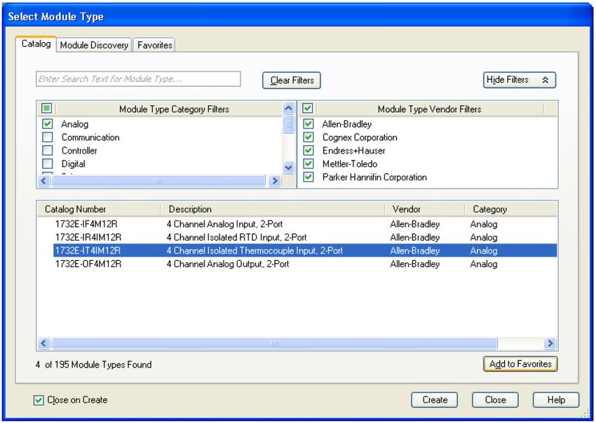
Table of Contents

                                                  Preface
                                                  About This Publication . . . . . . . . . . . . . . . . . . . . . . . . . . . . . . . . . . . . . . . . . . .                   7
                                                  Who Should Use this Manual. . . . . . . . . . . . . . . . . . . . . . . . . . . . . . . . . . . . . .                          7
                                                  Download Firmware, AOP, EDS, and Other Files . . . . . . . . . . . . . . . . . . . .                                           7
                                                  Studio 5000 Logix Designer Application. . . . . . . . . . . . . . . . . . . . . . . . . . . .                                  7
                                                  Summary of Changes. . . . . . . . . . . . . . . . . . . . . . . . . . . . . . . . . . . . . . . . . . . . .                    7
                                                  Additional Resources . . . . . . . . . . . . . . . . . . . . . . . . . . . . . . . . . . . . . . . . . . . . .                 8

                                                  Chapter 1
About the ArmorBlock Analog                       Overview . . . . . . . . . . . . . . . . . . . . . . . . . . . . . . . . . . . . . . . . . . . . . . . . . . . . . . . . 9
Input and Output Modules                          Module Features . . . . . . . . . . . . . . . . . . . . . . . . . . . . . . . . . . . . . . . . . . . . . . . . . 9
                                                  Physical Features of
                                                  Your Modules. . . . . . . . . . . . . . . . . . . . . . . . . . . . . . . . . . . . . . . . . . . . . . . . . . . 10
                                                  Types of Modules . . . . . . . . . . . . . . . . . . . . . . . . . . . . . . . . . . . . . . . . . . . . . . . 10
                                                  Hardware/Software Compatibility. . . . . . . . . . . . . . . . . . . . . . . . . . . . . . . . 11
                                                  Input and Output Types . . . . . . . . . . . . . . . . . . . . . . . . . . . . . . . . . . . . . . . . . 11
                                                  Alarms/Limits . . . . . . . . . . . . . . . . . . . . . . . . . . . . . . . . . . . . . . . . . . . . . . . . . . 11
                                                      Process Alarms . . . . . . . . . . . . . . . . . . . . . . . . . . . . . . . . . . . . . . . . . . . . . . 11
                                                      Clamping . . . . . . . . . . . . . . . . . . . . . . . . . . . . . . . . . . . . . . . . . . . . . . . . . . . 12
                                                      Overrange and Underrange Detection . . . . . . . . . . . . . . . . . . . . . . . . . 12
                                                  Digital Filters . . . . . . . . . . . . . . . . . . . . . . . . . . . . . . . . . . . . . . . . . . . . . . . . . . . 12
                                                  Chapter Summary . . . . . . . . . . . . . . . . . . . . . . . . . . . . . . . . . . . . . . . . . . . . . . 12

                                                  Chapter 2
Install Your ArmorBlock Module Overview . . . . . . . . . . . . . . . . . . . . . . . . . . . . . . . . . . . . . . . . . . . . . . . . . . . . . . . 13
                                                  Install the Module. . . . . . . . . . . . . . . . . . . . . . . . . . . . . . . . . . . . . . . . . . . . . . .               13
                                                      Set the Network Address . . . . . . . . . . . . . . . . . . . . . . . . . . . . . . . . . . . . .                         13
                                                  Mount the Module . . . . . . . . . . . . . . . . . . . . . . . . . . . . . . . . . . . . . . . . . . . . . .                  14
                                                  Wire the Module . . . . . . . . . . . . . . . . . . . . . . . . . . . . . . . . . . . . . . . . . . . . . . . .               16
                                                  Chapter Summary . . . . . . . . . . . . . . . . . . . . . . . . . . . . . . . . . . . . . . . . . . . . . .                   18

                                                  Chapter 3
Configure Your Analog Input and Overview . . . . . . . . . . . . . . . . . . . . . . . . . . . . . . . . . . . . . . . . . . . . . . . . . . . . . . . 19
Output Modules                  Set Up the Hardware . . . . . . . . . . . . . . . . . . . . . . . . . . . . . . . . . . . . . . . . . . . . 19
                                                  Create the
                                                  Example Application . . . . . . . . . . . . . . . . . . . . . . . . . . . . . . . . . . . . . . . . . . . . 20
                                                  Configure Your I/O Module . . . . . . . . . . . . . . . . . . . . . . . . . . . . . . . . . . . . . . 21
                                                  Overview of the Configuration Process in Studio 5000 Logix Designer
                                                  . . . . . . . . . . . . . . . . . . . . . . . . . . . . . . . . . . . . . . . . . . . . . . . . . . . . . . . . . . . . . . . . 21
                                                  Add a New Bridge and Module to Your Project . . . . . . . . . . . . . . . . . . . . . 21
                                                         Add the Local EtherNet/IP Bridge to the I/O Configuration . . . . . . 22
                                                         Add the I/O module as a child of the 1756-EN2T module . . . . . . . . . 23
                                                  Download the Program to Your Controller. . . . . . . . . . . . . . . . . . . . . . . . . 25
                                                  Edit Your 1732E-IF4M12R Configuration . . . . . . . . . . . . . . . . . . . . . . . . . . 25
                                                         General Tab . . . . . . . . . . . . . . . . . . . . . . . . . . . . . . . . . . . . . . . . . . . . . . . . . 27

                                         Rockwell Automation Publication 1732E-UM005B-EN-E - February 2022                                                                        3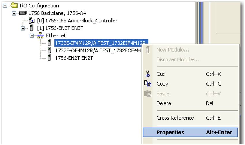
Table of Contents

                                        Connection Tab . . . . . . . . . . . . . . . . . . . . . . . . . . . . . . . . . . . . . . . . . . . . . 28
                                        Configuration Tab . . . . . . . . . . . . . . . . . . . . . . . . . . . . . . . . . . . . . . . . . . . 29
                                        Alarm Configuration Tab . . . . . . . . . . . . . . . . . . . . . . . . . . . . . . . . . . . . . 30
                                        Internet Protocol Tab . . . . . . . . . . . . . . . . . . . . . . . . . . . . . . . . . . . . . . . . 31
                                        Port Configuration Tab . . . . . . . . . . . . . . . . . . . . . . . . . . . . . . . . . . . . . . 32
                                        Calibration Tab. . . . . . . . . . . . . . . . . . . . . . . . . . . . . . . . . . . . . . . . . . . . . . 33
                                    Edit Your 17 32E-OF4M12R Configuration . . . . . . . . . . . . . . . . . . . . . . . . . 34
                                        General Tab . . . . . . . . . . . . . . . . . . . . . . . . . . . . . . . . . . . . . . . . . . . . . . . . . 35
                                        Connection Tab . . . . . . . . . . . . . . . . . . . . . . . . . . . . . . . . . . . . . . . . . . . . . 36
                                        Configuration Tab . . . . . . . . . . . . . . . . . . . . . . . . . . . . . . . . . . . . . . . . . . 37
                                        Limits Configuration Tab . . . . . . . . . . . . . . . . . . . . . . . . . . . . . . . . . . . . 38
                                        Fault/Program Action Tab . . . . . . . . . . . . . . . . . . . . . . . . . . . . . . . . . . . . 39
                                        Internet Protocol Tab . . . . . . . . . . . . . . . . . . . . . . . . . . . . . . . . . . . . . . . . 40
                                        Port Configuration Tab . . . . . . . . . . . . . . . . . . . . . . . . . . . . . . . . . . . . . . 41
                                        Calibration Tab. . . . . . . . . . . . . . . . . . . . . . . . . . . . . . . . . . . . . . . . . . . . . . 42
                                    Status and Monitoring Tabs. . . . . . . . . . . . . . . . . . . . . . . . . . . . . . . . . . . . . . 43
                                    Chapter Summary . . . . . . . . . . . . . . . . . . . . . . . . . . . . . . . . . . . . . . . . . . . . . . 43

                                    Chapter 4
Configurable Features for the       Overview . . . . . . . . . . . . . . . . . . . . . . . . . . . . . . . . . . . . . . . . . . . . . . . . . . . . . . .   45
Analog Input and Output             Configurable Features for the 1732E-IF4M12R Input Module . . . . . . . .                                                 45
                                       Input Types and Ranges . . . . . . . . . . . . . . . . . . . . . . . . . . . . . . . . . . . . . .                    45
Modules
                                       Digital Filters . . . . . . . . . . . . . . . . . . . . . . . . . . . . . . . . . . . . . . . . . . . . . . .         46
                                       High Engineering/Low Engineering. . . . . . . . . . . . . . . . . . . . . . . . . . .                                 47
                                       Real-time Sampling. . . . . . . . . . . . . . . . . . . . . . . . . . . . . . . . . . . . . . . . . .                 47
                                       Process Alarms . . . . . . . . . . . . . . . . . . . . . . . . . . . . . . . . . . . . . . . . . . . . . .            47
                                    Configurable Features for the 1732E-OF4M12R Output Module . . . . . .                                                    48
                                       Output Types and Ranges . . . . . . . . . . . . . . . . . . . . . . . . . . . . . . . . . . . .                       48
                                       High Engineering/Low Engineering. . . . . . . . . . . . . . . . . . . . . . . . . . .                                 48
                                       Fault Mode and Program Mode . . . . . . . . . . . . . . . . . . . . . . . . . . . . . . .                             48
                                       Clamping/Limiting . . . . . . . . . . . . . . . . . . . . . . . . . . . . . . . . . . . . . . . . . .                 49
                                    Data Tables. . . . . . . . . . . . . . . . . . . . . . . . . . . . . . . . . . . . . . . . . . . . . . . . . . . . .     50
                                    Chapter Summary . . . . . . . . . . . . . . . . . . . . . . . . . . . . . . . . . . . . . . . . . . . . . .              52

                                    Chapter 5
Calibrate Your Modules              Overview . . . . . . . . . . . . . . . . . . . . . . . . . . . . . . . . . . . . . . . . . . . . . . . . . . . . . . . 53
                                    Difference of Calibrating an Input Module and an Output Module. . . 53
                                        Calibrate in Program or Run Mode . . . . . . . . . . . . . . . . . . . . . . . . . . . . 54
                                    Calibrate the Input Module (1732E-IF4M12R) . . . . . . . . . . . . . . . . . . . . . . 54
                                    Calibrate the Output Module (1732E-OF4M12R) . . . . . . . . . . . . . . . . . . . . 57
                                        Current Meter Calibrations . . . . . . . . . . . . . . . . . . . . . . . . . . . . . . . . . . . 57
                                        Voltage Meter Calibrations . . . . . . . . . . . . . . . . . . . . . . . . . . . . . . . . . . . 60
                                    Chapter Summary . . . . . . . . . . . . . . . . . . . . . . . . . . . . . . . . . . . . . . . . . . . . . . 63

                                    Chapter 6
Troubleshoot the Modules            Interpret Status Indicators. . . . . . . . . . . . . . . . . . . . . . . . . . . . . . . . . . . . . . . 65
                                    Check for Faults . . . . . . . . . . . . . . . . . . . . . . . . . . . . . . . . . . . . . . . . . . . . . . . . 66

4                          Rockwell Automation Publication 1732E-UM005B-EN-E - February 2022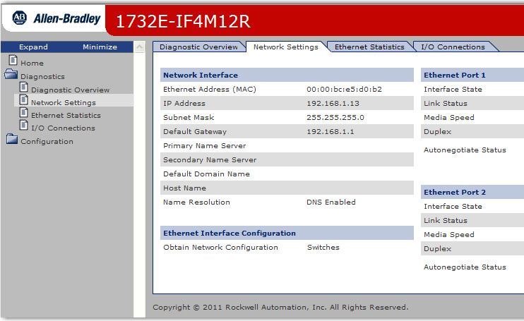
Table of Contents
Appendix A
Specifications General Specifications. . . . . . . . . . . . . . . . . . . . . . . . . . . . . . . . . . . . . . . . . . . 69
Input Specifications. . . . . . . . . . . . . . . . . . . . . . . . . . . . . . . . . . . . . . . . . . . . . 69
Output Specifications . . . . . . . . . . . . . . . . . . . . . . . . . . . . . . . . . . . . . . . . . . . 70
Environmental Specifications . . . . . . . . . . . . . . . . . . . . . . . . . . . . . . . . . . . . 70
Certifications. . . . . . . . . . . . . . . . . . . . . . . . . . . . . . . . . . . . . . . . . . . . . . . . . . . 71
Appendix B
ArmorBlock Embedded Web Introduction. . . . . . . . . . . . . . . . . . . . . . . . . . . . . . . . . . . . . . . . . . . . . . . . . . . . 73
Server Typical Applications . . . . . . . . . . . . . . . . . . . . . . . . . . . . . . . . . . . . . . . . . . . . . 73
Browser Requirements . . . . . . . . . . . . . . . . . . . . . . . . . . . . . . . . . . . . . . . . . . 73
Enable or Disable the Web Server. . . . . . . . . . . . . . . . . . . . . . . . . . . . . . . . . 74
Access the Home Page of the Web Server . . . . . . . . . . . . . . . . . . . . . . . . . . 75
Log On to the Web Server . . . . . . . . . . . . . . . . . . . . . . . . . . . . . . . . . . . . . . . . 75
Navigate the ArmorBlock
I/O Module . . . . . . . . . . . . . . . . . . . . . . . . . . . . . . . . . . . . . . . . . . . . . . . . . . . . . 76
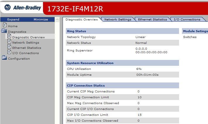
Access Diagnostic Information . . . . . . . . . . . . . . . . . . . . . . . . . . . . . . . . . . . 76
Access Configuration Information. . . . . . . . . . . . . . . . . . . . . . . . . . . . . . . . 77
Appendix C
Module Tag Definitions Module Tags for 1732E-IF4M12R. . . . . . . . . . . . . . . . . . . . . . . . . . . . . . . 79
Module Tags for 1732E-OF4M12R . . . . . . . . . . . . . . . . . . . . . . . . . . . . . . 81
Access the Module Tags. . . . . . . . . . . . . . . . . . . . . . . . . . . . . . . . . . . . . . . . . . 82
Index
. . . . . . . . . . . . . . . . . . . . . . . . . . . . . . . . . . . . . . . . . . . . . . . . . . . . . . . . . . . . . . . . 83
Rockwell Automation Publication 1732E-UM005B-EN-E - February 2022 5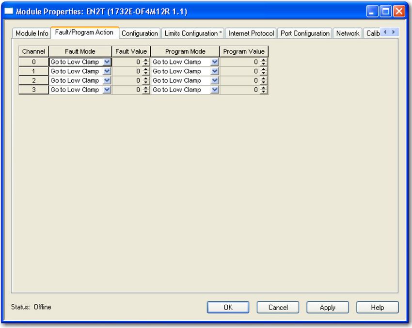
Table of Contents

Notes:

6                   Rockwell Automation Publication 1732E-UM005B-EN-E - February 2022
Preface

About This Publication            This manual is a reference guide for the 1732E-IF4M12R, 1732E-OF4M12R
                                  modules. It describes the procedures that you use to install, wire, configure,
                                  troubleshoot, and use your module.

                                  Rockwell Automation recognizes that some of the terms that are currently
                                  used in our industry and in this publication are not in alignment with the
                                  movement toward inclusive language in technology. We are proactively
                                  collaborating with industry peers to find alternatives to such terms and
                                  making changes to our products and content. Please excuse the use of such
                                  terms in our content while we implement these changes.

Who Should Use this Manual        Use this manual if you are responsible for designing, installing, programming,
                                  or troubleshooting control systems that use ArmorBlock® EtherNet/IP™ Dual
                                  Port Dual-Port 4-Point Analog Input and Output Modules.

                                  You should have a basic understanding of electrical circuitry and familiarity
                                  with relay logic. If you do not, obtain the proper training before using this
                                  product.

Download Firmware, AOP,           Download firmware, associated files (such as AOP, EDS, and DTM), and access
EDS, and Other Files              product release notes from the Product Compatibility and Download Center at
                                  rok.auto/pcdc.

Studio 5000 Logix Designer        The Studio 5000 Logix Designer® application is the rebranding of
Application                       RSLogix 5000® software and continues to be the product to program
                                  Logix 5000™ controllers for discrete, process, batch, motion, safety, and drive
                                  based solutions.

Summary of Changes                This publication contains the following new or updated information. This list
                                  includes substantive updates only and is not intended to reflect all changes.

                                  Topic                                                                Page
                                  Updated template                                                  Throughout
                                  Added inclusive language acknowledgment                                7
                                  Added section Enable or Disable the Web Server to Appendix B          74
                                  Corrected web server user name and password details                   75

                         Rockwell Automation Publication 1732E-UM005B-EN-E - February 2022                          7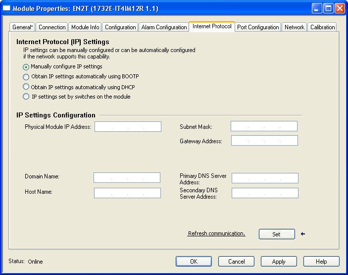
Preface

Additional Resources                                   These documents contain additional information concerning related products
                                                       from Rockwell Automation.

Resource                                                                      Description
1732E ArmorBlock Dual-Port EtherNet/IP 4-Point Analog Modules,                Information on wiring the ArmorBlock Dual-Port EtherNet/IP 4-point Analog Modules
publication 1732E-WD003
1732E ArmorBlock Dual-Port EtherNet/IP 4-Point Analog Input and Output        Information on installing the ArmorBlock EtherNet/IP module.
Modules Installation Instructions, publication 1732E-IN006
                                                                            A manual on how to install, configure, and maintain linear and Device Level Ring (DLR)
EtherNet/IP Embedded Switch Technology Application Guide,                   networks using Rockwell Automation EtherNet/IP devices with embedded switch
publication ENET-AP005                                                      technology.
                                                                            Describes how to configure and use EtherNet/IP devices to communicate on the EtherNet/IP
EtherNet/IP Network Devices User Manual, ENET-UM006                         network.
Ethernet Reference Manual, ENET-RM002                                       Describes basic Ethernet concepts, infrastructure components, and infrastructure features.
                                                                            Provides guidance on how to conduct security assessments, implement Rockwell
System Security Design Guidelines Reference Manual, SECURE-RM001            Automation products in a secure system, harden the control system, manage user access,
                                                                            and dispose of equipment.
Industrial Components Preventive Maintenance, Enclosures, and Contact       Provides a quick reference tool for Allen-Bradley industrial automation controls and
Ratings Specifications, publication IC-TD002                                assemblies.
                                                                            Designed to harmonize with NEMA Standards Publication No. ICS 1.1-1987 and provides
Safety Guidelines for the Application, Installation, and Maintenance of     general guidelines for the application, installation, and maintenance of solid-state control in
Solid-state Control, publication SGI-1.1                                    the form of individual devices or packaged assemblies incorporating solid-state
                                                                            components.
Industrial Automation Wiring and Grounding Guidelines, publication 1770-4.1 Provides general guidelines for installing a Rockwell Automation industrial system.
Product Certifications website, rok.auto/certifications.                    Provides declarations of conformity, certificates, and other certification details.

                                                       You can view or download publications at rok.auto/literature.

8                                            Rockwell Automation Publication 1732E-UM005B-EN-E - February 2022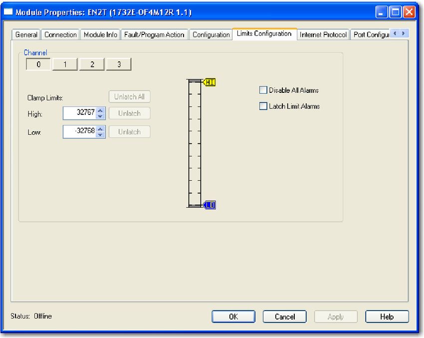
Chapter     1

                           About the ArmorBlock Analog Input and Output
                           Modules

Overview                   This chapter provides an introduction to the features and functionalities of the
                           ArmorBlock EtherNet/IP Dual-Port 4-point Analog Input and Output Modules,
                           1732E-IF4M12R and 1732EOF4M12R.

                           Topic                                                      Page
                           Module Features                                            9
                           Physical Features of Your Modules                          10
                           Types of Modules                                           10
                           Hardware/Software Compatibility                            11
                           Input and Output Types                                     11
                           Alarms/Limits                                              11
                           Digital Filters                                            12

Module Features            ArmorBlock analog I/O modules are interface modules that convert analog
                           signals to digital values for inputs and convert digital values to analog signals
                           for outputs. Controllers can then use these signals for control purposes.

                           By using the producer/consumer network model, ArmorBlock analog I/O
                           modules produce information when needed.

                           The modules have the following features:
                              •   Multiple preset ranges of voltage or current inputs/outputs
                              •   Process alarms and limits
                              •   Overrange and underrange detection
                              •   Digital filter for 1732E-IF4M12R

                           To learn more about module features, see Configurable Features for the Analog
                           Input and Output Modules on page 45.

                           You must use the Studio 5000 Logix Designer application to configure these
                           features. For a detailed how-to-configure instructional guide, see the chapter,
                           Configure Your Analog Input and Output Modules on page 19.

                  Rockwell Automation Publication 1732E-UM005B-EN-E - February 2022                            9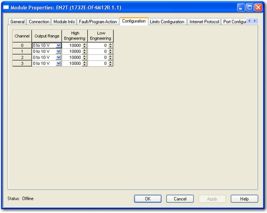
Chapter 1   About the ArmorBlock Analog Input and Output Modules

Physical Features of                           The modules have the following components:
Your Modules                                         •       Node address switches
                                                     •       Connectors (two EtherNet/IP D-code M12 connectors, two micro-style
                                                             Power in/out connectors, four I/O M12 connectors)
                                                     •       Status indicators (Link, I/O, Module, Network, and Auxiliary power
                                                             status indicators)
                                                     •       Functional earth ground
                                               Physical Features of 1732E-IF4M12R and 1732E-OF4M12R Modules
                                                                                                                                          Functional earth ground(1)

                                                                       EtherNet/IP D-code                                                 EtherNet/IP D-code
                                                                     M12 connector - Link 1                                               M12 connector - Link 2

                                                                     Link 1 status indicator                                              Link 2 status indicator
                                                                    Module status indicator                                               Network status indicator

                                                                   Node address switches                                                      Node address switches

                                                                                I/O status
                                                                               indicators
                                                                                                                                            M12 style, A-coded
                                                                                                                                            I/O connectors

                                                                               Auxiliary power
                                                                              status indicator

                                                                         Micro-style power in                                           Micro-style power out

                                               (1)       Functional earth grounds the I/O block’s EtherNet/IP communication circuitry, which is designed to mitigate the effect of
                                                         noise on the network. The device requires a solid earth ground connection, either through a metal screw to a grounded metal
                                                         panel or through a wire.

Types of Modules                               The analog input and output modules are as follows.

                                               Module Description
                                                                                                                                      Network                    Power
                                                Catalog Number                    Description                                         Connector                  Connector
                                                                                  24V DC power, 4-point Analog Input, Dual-
                                                1732E-IF4M12R                     port EtherNet/IP Module
                                                                                                                                      Dual D-code M12            Dual 4-pin micro
                                                                                  24V DC power, 4-point Analog Output, Dual-
                                                1732E-OF4M12R                     port EtherNet/IP Module

10                                    Rockwell Automation Publication 1732E-UM005B-EN-E - February 2022
Chapter 1 About the ArmorBlock Analog Input and Output Modules
Hardware/Software The module and the applications described in this manual are compatible with
Compatibility the following firmware revisions and software versions.
Module Compatibility
Product Firmware Revision / Software Version
1732E-IF4M12R and 1732E-OF4M12R Firmware revision 1.1 or later
1756-EN2T, 1756-EN2TR, 1756-EN3TR 3.x revision when using Studio 5000 Logix Designer v20 or later
Studio 5000 Logix Designer application 20 or later
RSLinx software 2.56 or later
Input and Output Types The 1732E-IF4M12R module supports four input channels, while the
1732E-OF4M12R supports four output channels. Each of the four input/output
channels can be configured as either current or voltage input/output, with
current mode as default configuration.
You can select from a series of operational ranges for each channel. The range
designates the minimum and maximum signals that are detectable by the
module.
Input/Output Ranges for 1732E-IF4M12R and 1732E-OF4M12R
Module Input/Output Range
1732E-IF4M12R 0…20 mA
4…20 mA
0…10 V
1732E-OF4M12R -10…10 V
0…5 V
-5…5 V
To use an input or output as a current or voltage device, you must:
• Wire the input/output connector for the correct input type (see page 16).
• Configure the input/output as current or voltage using Studio 5000
Logix Designer application (see page 29 and page 37).
Alarms/Limits The modules are capable of generating the following alarms:
• Process alarms (low, low-low, high, high-high) for 1732E-IF4M12R
• Clamp/limits alarm for 1732E-OF4M12R
Process Alarms
The following level alarms are available for the for 1732E-IF4M12R module:
• Low
• Low-Low
• High
• High-High
When the channel input goes below a low alarm or above a high alarm, a bit is
set in the data table. All Alarm Status bits can be read individually or by reading
the Channel Status Byte (see page 50).
Rockwell Automation Publication 1732E-UM005B-EN-E - February 2022 11Chapter 1 About the ArmorBlock Analog Input and Output Modules
You can configure each channel alarm individually. See Alarm Configuration
Tab on page 30 to learn how to configure the alarms.
Clamping
Clamping limits the output from the analog module to remain within a range
configured by the controller, even when the controller commands an output
outside that range. This safety feature sets a high clamp and a low clamp.
Once clamps are determined for a module, any data received from the
controller that exceeds those clamps sets an appropriate limit alarm and
transitions the output to that limit but not beyond the requested value.
Clamping alarms can be disabled or latched on a per channel basis.
To learn how to set clamp limits, see Limits Configuration Tab on page 38.
Overrange and Underrange Detection
This feature detects when the input module is operating beyond limits set by
the input range. For example, if you are using the 1732E-IF4M12R module in
the 0V…10V input range and the module voltage increases to 11V, the
overrange detects this condition.
The table shows the input ranges of the input module and the lowest/highest
signal available in each range before the module detects an underrange/
overrange condition.
Lowest and Highest Signal for Overrange and Underrange Detection
Available Range Lowest Signal in Range Highest Signal in Range
0…20 mA 0 mA 20 mA
4…20 mA 4 mA 20 mA
0…10 V 0V 10 V
-10…10 V -10 V 10 V
0…5 V 0V 5V
-5…5 V -5 V 5V
Digital Filters The 1732E-IF4M12R module also supports a digital filter to smooth input data
noise transients on each input channel. This value specifies the time constant
for a digital first order lowpass filter on the input. It is specified in units of
milliseconds. A value of 0 disables the filter.
To learn more about digital filter, see page 46.
Chapter Summary In this chapter, you were introduced to the features of the analog input and
output modules.
12 Rockwell Automation Publication 1732E-UM005B-EN-E - February 2022Chapter 2
Install Your ArmorBlock Module
Overview This chapter shows you how to install and wire the analog input and output
modules. The only tools you require are a screwdriver and drill.
Topics Page
Install the Module 13
Set the Network Address 13
Mount the Module 14
Wire the Module 16
Install the Module To install the module:
• Set the network address
• Mount the module
• Connect I/O, Network, and Auxiliary cables to the module
Set the Network Address
The I/O block ships with the rotary switches set to 999 and DHCP enabled. To
change the network address, you can do one of the following:
• Adjust the node address switches on the front of the module.
• Use a Dynamic Host Configuration Protocol (DHCP) server, such as
Rockwell Automation BootP/DHCP.
• Retrieve the IP address from nonvolatile memory.
The I/O block reads the switches first to determine if the switches are set to a
valid number. To set the network address:
1. Remove power.
2. Remove the switch dust caps.
3. Rotate the three (3) switches on the front of the module using a small
blade screwdriver.
4. Line up the small notch on the switch with the number setting you wish
to use.
Valid settings range from 001…254.
5. Replace switch dust caps. Make sure not to over tighten.
6. Reapply power.
7. Record IP address on product label found on the side of enclosure.
Rockwell Automation Publication 1732E-UM005B-EN-E - February 2022 13Chapter 2 Install Your ArmorBlock Module
Set Network Address
Example shows network switches set at 2
163, which sets the module IP address to 0 4
192.168.1.163.
8 6
2 2
Note: You need to remove the protective 4
0 4
switch dust caps before you can adjust 0
the address settings. 6
8 6
8
When the switches are set to a valid number, the I/O block’s IP address is
192.168.1.xxx, where xxx represents the number set on the switches. The I/O
block’s subnet mask is 255.255.255.0 and default gateway address is set to
192.168.1.1.
When the I/O block uses the network address set on the switches, the I/O block
does not have a host name assigned to it or use any Domain Name Server.
If the switches are set to an invalid number (for example, 000 or a value greater
than 254 excluding 888), the I/O block checks to see if DHCP is enabled. If
DHCP is enabled, the I/O block asks for an address from a DHCP server. The
DHCP server also assigns other Transport Control Protocol (TCP) parameters.
(The modules are shipped with the network switches set to 999.)
If DHCP is not enabled, the I/O block uses the IP address (along with other
TCP configurable parameters) stored in nonvolatile memory.
Network Address Switch value 001
The module IP address cannot be the same as the gateway address. If the
address switches are set to 001, the module IP address becomes 192.168.1.1,
which is the same as the default gateway address. In this case, the module
gateway address will be set to 0.0.0.0.
Default Factory Configuration
The switch value 888 resets the module to default factory configuration on
power up. The module will not operate properly when powered up with this
setting. The switches must be set to a different (and valid) value and then
power cycled after a reset.
While in reset state, the module LED flashes red and the network LED goes off.
Mount the Module Two sets of mounting holes are used to mount the module directly to a panel or
machine. Mounting holes accommodate #6 (M3) pan head screws. The torque
specification is 0.68 N•m (6 lb•in).
To mount the module on a wall or panel, use the screw holes provided in the
module. Refer to the drilling dimensions illustration to guide you in mounting
the module.
14 Rockwell Automation Publication 1732E-UM005B-EN-E - February 2022Chapter 2 Install Your ArmorBlock Module
Mounting Dimensions
37 (1.46) 19.8 Millimeters
16.2 (0.64) (0.78)
(Inches)
Functional Earth
Grounds the I/O block EtherNet/IP
communication circuitry which is
designed to mitigate the effect of
noise on the network. It requires a
solid earth ground connection, either
through a metal screw to a grounded
metal panel or through a wire.
166.5 (6.56)
179 (7.05)
168.6 (6.64)
27
(1.06)
Side mounting
6LGH0RXQWLQJ
43.3
(1.70)
32 18
(1.26) (0.71)
Front mounting
)URQW0RXQWLQJ 45870
Install the mounting base as follows:
1. Lay out the required points as shown above in the drilling dimension
drawing.
2. Drill the necessary holes for #6 (M3) pan head screws.
3. Mount the module using #6 (M3) screws.
Mount the Module in High Vibration Areas
If you mount the module in an area that is subject to shock or vibration, we
recommend you use a flat and a lock washer to mount the module. Mount the
flat and the lock washer as shown in the mounting illustration. Torque the
mounting screws to 0.68 N•m (6 lb•in).
Rockwell Automation Publication 1732E-UM005B-EN-E - February 2022 15Chapter 2 Install Your ArmorBlock Module
High Vibration Area Mounting
Lock washer
Flat washer
45768
Wire the Module The 1732E-IF4M12R, 1732E-OF4M12R ArmorBlock EtherNet/IP modules have 5-
pin micro-style M12 I/O connectors. We provide caps to cover the unused
connectors on your module. Connect the quick-disconnect cord sets you
selected for your module to the appropriate ports.
I/O Connectors(a)
Figure 1 - Micro-style M12 5-Pin Input Female Connector – 1732E-IF4M12R
(View into connector)
3 Pin 1 Current Input +
2 Pin 2 Current Common
5 Pin 3 Voltage Input +
4 Pin 4 Voltage Common
1 Pin 5 No Connect
45868
Micro-style M12 5-Pin Input Female Connector – 1732E-OF4M12R
(View into connector)
3 Pin 1Current Output +
2 Pin 2Current Common
5 Pin 3Voltage Output +
4 Pin 4Voltage Common
1 Pin 5No Connect
45868
Ethernet Connector
D-Code Micro Network Female Connector
5 (View into connector 1)
1 Pin 1M12_Tx+
Pin 2 M12_Rx+
4 2 Pin 3 M12_Tx-
Pin 4 M12_Rx-
3 Pin 5 Connector shell shield GND
44808
(a) Only 4 of the 5 pins are active. The center pin (5) is internally tied to signal ground to minimize external noise pickup.
16 Rockwell Automation Publication 1732E-UM005B-EN-E - February 2022Chapter 2 Install Your ArmorBlock Module
IMPORTANT Use the 1585D–M4DC–H: Polyamide small body unshielded mating
connectors for the D-Code M12 female network connector.
Note that the distance between the center of each Ethernet
connector is 16.2 mm (see Mounting Dimensions on page 15).
Rockwell Automation recommends the use of suitable cable based on
this measurement. Some of the recommended cables are 1585D-
M4TBJM-x and 1585D-M4TBDM-x for daisychains.
IMPORTANT Use two twisted pair CAT5E UTP or STP cables.
D-Code M12 Pin Wire Color Signal 8-way Modular RJ45 Pin
1 White-orange TX+ 1
2 White-green RX+ 3
3 Orange TX- 2
4 Green RX- 6
Power Connectors
Attach the mini-style 4-pin connector to the mini-style 4-pin receptacle as
shown below.
Micro-style 4-Pin Input Male Receptacle
Male Input Female Output
(View into receptacle)
2 Pin 1 Auxiliary power+ 2
Pin 2 Module power+
3 1 Pin 3 Module power- 1 3
Pin 4 Auxiliary power-
4 4
45764 45763
The power required by the module is based on a 4-pin micro-style connector
system. Power can be daisy chained through the module either left to right or
right to left. The standard configuration is with Module/Auxiliary power
entering the module on the left connector.
Both modules require two 24V DC (nominal) supplies. These supplies are called
the Module Power and the Auxiliary Power. The Module power supplies the
microprocessor and Ethernet portions of the module. The Auxiliary Power
provides power for the voltage or current outputs on the 1732E-OF4M12R
analog output module.
Internally, the Module Power and Auxiliary Power are electrically isolated.
IMPORTANT The maximum current that any pin on the power connectors can
carry is 4 A.
ATTENTION: To comply with the CE Low Voltage Directive (LVD), this
equipment and all connected I/O must be powered from a source compliant
with the following:
Safety Extra Low Voltage (SELV) or Protected Extra Low Voltage (PELV).
ATTENTION: To comply with UL restrictions, this equipment must be
powered from a source compliant with the following: Limited Voltage/
Limited Current.
ATTENTION: The device meets UL Type 1 Enclosure rating.
Rockwell Automation Publication 1732E-UM005B-EN-E - February 2022 17Chapter 2 Install Your ArmorBlock Module
Chapter Summary In this chapter, you learned how to install and wire your module. The following
chapter describes how to configure your module to communicate on the
EtherNet/IP network by providing an IP address, gateway address, and Subnet
mask.
18 Rockwell Automation Publication 1732E-UM005B-EN-E - February 2022Chapter 3
Configure Your Analog Input and Output Modules
Overview This chapter guides you through the steps required to configure your modules
using the Studio 5000 Logix Designer application. Note that the modules
presented in this chapter can be configured using Studio 5000 Logix Designer
application, version 20 or later.
Topic Page
Set Up the Hardware 19
Create the Example Application 20
Configure Your I/O Module 21
Overview of the Configuration Process in Studio 5000 Logix Designer 21
Add a New Bridge and Module to Your Project 21
Download the Program to Your Controller 25
Edit Your 1732E-IF4M12R Configuration 25
Edit Your 1732E-OF4M12R Configuration 34
Status and Monitoring Tabs 43
Adding the two modules through the Studio 5000 Logix Designer application
involve the same general procedure. Note, however, that the two modules do
not have exactly similar Module Definition properties or configuration
parameters. Both modules are distinctly covered in this chapter.
Set Up the Hardware In this example, a ControlLogix® chassis contains the Logix 5565 controller in
slot 1 and a 1756-EN2T bridge module in slot 3. The ArmorBlock module is
mounted remotely.
ArmorBlock Ethernet
Slot 0 1 2 3 module
192.168.1.3
Logix5565 EtherNet/IP
Local
chassis ArmorBlock
1756-EN2T
Logix5565
Data module
Logix 5565 1756-EN2T
controller (slot 1) 192.168.1.20 (slot 3)
Switch
Embedded
technology
192.168.1.100
Programming
terminal
44971
Rockwell Automation Publication 1732E-UM005B-EN-E - February 2022 19Chapter 3 Configure Your Analog Input and Output Modules
To work along with this example set up your system as shown:
• Note that in the example application, the Logix 5565 controller and
1756-EN2T module (firmware revision 2.3 or higher) are assumed to be in
the slots shown.
• Verify the IP addresses for your programming terminal, 1756-EN2T
module and ArmorBlock Ethernet module.
• Verify that you connected all wiring and cabling properly.
• Be sure you configured your communication driver (for example,
AB_ETH-1 or AB-ETHIP-1) in RSLinx® software.
Create the Perform the following steps to create the example application:
Example Application 1. From the File menu, select New.
The New Controller dialog opens.
2. Enter an appropriate name for the Controller, for example,
ArmorBlock_IO_Controller.
20 Rockwell Automation Publication 1732E-UM005B-EN-E - February 2022Chapter 3 Configure Your Analog Input and Output Modules
3. Select the correct version, chassis type, and slot number of the controller,
and the folder where you want to save the Studio 5000 Logix Designer
application file (Create In). The Description is optional.
To use redundancy in your system, select the Redundancy Enabled
checkbox.
4. Click OK.
Configure Your I/O Module You must configure your module upon installation. The module will not work
until it has been configured with at least the default configuration.
You must use Studio 5000 Logix Designer application, version 20 or later, to
configure your module. You have the option of accepting default configuration
for your module or writing point-level configuration specific to your
application.
Both options are explained in detail, including views of software screens, in
this chapter.
Overview of the When you use the Studio 5000 Logix Designer application to configure a
Configuration Process in module, you must perform the following steps:
Studio 5000 Logix Designer 1. Add the Local EtherNet/IP Bridge (1756-EN2T, 1756-EN2TR, or
1756-EN3TR) to your project’s I/O Configuration.
2. Add the 1732E-IF4M12R or 1732E-OF4M12R module as a child of the
1756-EN2T module.
3. Accept the default configuration or change it to specific configuration
for the module.
4. Edit configuration for a module when changes are needed.
Add a New Bridge and After you have started Studio 5000 Logix Designer application and created a
Module to Your Project controller, you must add a new bridge and a new module to your project. The
bridge allows your module to communicate with the controller.
The wizard allows you to create a new module and write configuration. You
can use default configuration or write specific configuration for your
application.
IMPORTANT Click Help on the configuration dialogs shown in this section if you
need assistance in selecting and setting the parameters.
Rockwell Automation Publication 1732E-UM005B-EN-E - February 2022 21Chapter 3 Configure Your Analog Input and Output Modules
Add the Local EtherNet/IP Bridge to the I/O Configuration
1. If necessary, go offline.
If you are not offline, use this
pull-down menu to go offline.
2. Add the EtherNet/IP Bridge to your Studio 5000 Logix Designer project.
1. Right-click 1756 Backplane.
2. Select New Module.
3. Expand Communications and select the new module in the Select
Module dialog that appears. Select the 1756-EN2T EtherNet/IP Bridge.
1. Select the 1756-EN2T EtherNet/IP Bridge.
2. Click OK.
22 Rockwell Automation Publication 1732E-UM005B-EN-E - February 2022Chapter 3 Configure Your Analog Input and Output Modules
4. The New Module dialog opens.
Configure the bridge module as illustrated below.
1. Name the bridge.
2. Enter the IP address.
3. Select slot 3 for the EtherNet/IP bridge.
4. Make sure the Minor Revision number matches
your module revision number.
5. Choose an Electronic Keying method.
For more information, see page 27.
6. Click OK.
The local 1756-EN2T communication module will communicate with the
ArmorBlock module on Ethernet. Before you can communicate with your
module, you need to add it as a child of the 1756-EN2T communication module.
For more information about using 1756 controller and EtherNet/IP products,
see the EtherNet/IP Network Devices User Manual, publication ENET-UM006.
Add the I/O module as a child of the 1756-EN2T module
1. Right-click the Ethernet folder that appears below the 1756-EN2T bridge
you added to the I/O Configuration tree and select New Module.
2. On the Select Module Type dialog that appears, select the 1732E-IF4M12R
module and click Create.
If the 1732E-IF4M12R, 1732E-OF4M12R modules are not listed in the analog category
of the Select Module Type dialog, you may need to download the Add-On Profile
(AOP) and install it as an add-on to Studio 5000 Logix Designer application. The
AOP file can be downloaded from: rok.auto/pcdc.
Rockwell Automation Publication 1732E-UM005B-EN-E - February 2022 23Chapter 3 Configure Your Analog Input and Output Modules
3. The New Module dialog appears.
Fill in the Module Properties information as shown, and then click OK.
Module Properties Example
Field Name Value
Name TEST_1732EIF4M12R
IP Address 192.168.1.3
Electronic Keying Compatible Module
Revision 1.1
Input Only
Connection (This parameter is Exclusive Owner for 1732E-OF4M12R)
To add the 1732E-OF4M12R Analog output module, follow the same steps.
After adding the modules to your project, the I/O Configuration tree
should appear as follows:
This example uses default Module Definition and configuration
properties. To customize your module configuration, go to:
• Edit Your 1732E-IF4M12R Configuration on page 25
• Edit Your 1732E-OF4M12R Configuration on page 34
24 Rockwell Automation Publication 1732E-UM005B-EN-E - February 2022Chapter 3 Configure Your Analog Input and Output Modules
Download the Program to After you write configuration for your module, the module does not use this
Your Controller configuration until you download it to the owner-controller. The download
transfers the entire program to the controller, overwriting any existing
program.
Download module configuration as shown below:
1. Click here to see the
pull-down menu.
2. Click download.
Depending on your application, a variety of Studio 5000 Logix Designer
application screens may appear to choose a path to your ControlLogix
controller and to verify the download. Navigate those screens as best fits your
application.
This completes the download process.
Edit Your 1732E-IF4M12R Studio 5000 Logix Designer application automatically creates module-defined
Configuration data types and tags when a module is created. This section describes how to
modify the default configuration for input modules.
Data types symbolically name module configuration, input and output data.
Tags let you provide each a unique name, such as where the user-defined data
type and slot reside on the controller. This information is used to
communicate data between the controller and module.
After you have set configuration for a module, you can review and change your
choices. You can change configuration data and download it to the controller
while online. This is called dynamic reconfiguration.
Your freedom to change some configurable features, though, depends on
whether the controller is in Remote Run Mode or Program Mode.
IMPORTANT Although you can change configuration while online, you must go
offline to add or delete modules from the project.
The editing process begins on the main page of Studio 5000 Logix Designer
application.
Rockwell Automation Publication 1732E-UM005B-EN-E - February 2022 25Chapter 3 Configure Your Analog Input and Output Modules
1. On the I/O Configuration tree for your project, right-click the name of
your module.
2. Select Properties. The Module Properties dialog appears and has the
following tabs available for configuration.
3. Click any of the tabs to edit the parameters for your module.
The next sections show you how to edit the different tabs in the Module
Properties dialog.
Tabs can be selected in any order. The following examples are for
instructional purposes.
26 Rockwell Automation Publication 1732E-UM005B-EN-E - February 2022Chapter 3 Configure Your Analog Input and Output Modules
General Tab
The General tab allows you to edit general properties such as Name, IP
Address, and Description for your module. You also can edit Module
Definition properties such as revision, electronic keying, and data. To do so,
click Change.
Module Definition Fields
Field Name Description
Series Specifies the module series.
Revision Specifies the module’s major and minor revision.
The electronic keying feature automatically compares the expected module, as
shown in the Studio 5000 Logix Designer application I/O Configuration tree, to the
physical module before
I/O communication begins. You can use electronic keying to help prevent
communication to a module that does not match the type and revision expected.
For each module in the I/O Configuration tree, the user-selected keying option
determines if, and how, an electronic keying check is performed.
Typically, three keying options are available:
• Exact Match
• Compatible Module (default value)
• Disable Keying
Exact Match is an electronic keying protection mode that requires the physical
Electronic Keying module and the module configured in the software to match according to vendor,
catalog number, major revision and minor revision.
Compatible Module indicates that the module determines whether to accept or
reject communication. Compatible Keying is the default setting. It allows the
physical module to accept the key of the module configured in the software,
provided that the configured module is one the physical module is capable of
emulating. The exact level of emulation required is product and revision specific.
Disable Keying indicates the keying attributes are not considered when
attempting to communicate with a module. Other attributes, such as data size and
format, are considered and must be acceptable before I/O communication is
established. With Disabled Keying, I/O communication may occur with a module
other than the type specified in the I/O configuration tree with unpredictable
results. We generally do not recommend using Disabled Keying.
Available options are Data, Input Only, Exclusive Owner, and Listen Only.
Calibration and Configuration options are not available for Listen Only option.
Input Only specifies an independent connection where a device receives inputs
from the target device and sends configuration data to the target device. An Input
Only connection does not send outputs; it only receives inputs. You can specify
multiple Input Only connections to the target device from different originators.
Exclusive Owner specifies an independent connection where a single device
controls the output states in the target device. If you have an existing Exclusive
Connection Owner connection to a target device, you cannot specify another Exclusive Owner
or Redundant connection to that same target device.
Listen Only specifies a dependent connection where a device receives inputs
from the target device, but does not send configuration data with the target
device. A Listen Only connection only functions properly when another non-Listen
Only connection exists to the same target device. A Listen Only connection does
not send outputs; it only receives inputs. You can specify multiple Listen Only
connections to the target device from different originators.
Rockwell Automation Publication 1732E-UM005B-EN-E - February 2022 27Chapter 3 Configure Your Analog Input and Output Modules
Connection Tab
The Connection tab on the Module Properties dialog box lets you enter a
requested packet interval (RPI), inhibit a module, and set a connection fault
when the controller is in Run mode. The RPI provides a defined, maximum
period of time when data is transferred to the owner-controller.
1. Choose from the options on the Connection tab.
Connection Tab Fields
Field Description
A user-defined rate at which the module updates the information sent to its
Requested Packet Interval (RPI) owner-controller.
This interval defines the slowest rate at which a module sends its data to the
(ms) owner-controller. The time ranges from 2.0…750 ms and is sent to the module
with all other configuration parameters.
Check the box to prevent communication between the ownercontroller and the
Inhibit Module module. This option allows for maintenance of the module without faults being
reported to the controller.
Major Fault On Controller If Check the box to create a major fault if there is a connection failure with the
Connection Fails While in Run controller while in Run mode.
Mode
This option is enabled by default.
Use Unicast Connection over Unicast connections are point to point transmissions between a source node
EtherNet/IP and destination node on the network. A Frame is sent to
a single destination.
The fault box is empty if you are offline. The type of connection fault
Module Fault appears in the text box if a fault occurs when the module is online.
2. Do one of the following:
• Click Apply to store a change but stay on the dialog box to choose
another tab.
• Click OK if you are finished making changes.
28 Rockwell Automation Publication 1732E-UM005B-EN-E - February 2022Chapter 3 Configure Your Analog Input and Output Modules
Configuration Tab
The Configuration tab on the Module Properties dialog box lets you program
information on each of the four channels on the 1732E-IF4M12R module.
1. Choose from the options on the Configuration tab.
Configuration Tab Fields
Field Description
Channel Indicates the four input channels 0…3.
Input can be voltage or current, with current mode as default.
It has the following input range options:
Input Range
Serves to reject higher frequency noise and harmonics.
Digital Filter Choose a value in milliseconds that specifies the time constant for a digital first order
lowpass filter on the input. A value of 0 disables the filter.
High engineering value helps determine the engineering units the signal values scale
into. The high engineering term corresponds to the high signal value. The scaling
equation used is shown below.
High Engineering (Signal-LowSignal)(HighEngineering-LowEngineering)
Data = + Low Engineering
High Signal - Low Signal
One of four points used in scaling. The low engineering helps determine the
engineering units the signal values scale into. The low engineering term corresponds
to the low signal value. The scaling equation used is as follows:
Low Engineering (Signal-LowSignal)(HighEngineering-LowEngineering)
Data = + Low Engineering
High Signal - Low Signal
This parameter instructs the module how often to scan its input channels and obtain
Real Time Sample (RTS) all available data. This feature is applied on a module-wide basis.
Rockwell Automation Publication 1732E-UM005B-EN-E - February 2022 29Chapter 3 Configure Your Analog Input and Output Modules
2. Do one of the following:
• Click Apply to store a change but stay on the dialog box to choose
another tab.
• Click OK if you are finished making changes.
Alarm Configuration Tab
The Alarm Configuration tab on the Module Properties dialog box lets you
program high and low limits, and disable and latch alarms per channel.
Click Channel button to set limits and
alarm configuration for each of the 4
channels.
Use the sliders to set limits. HH slider
sets High High limits; HI sets High
limits; LL for Low Low; and LO for Low.
1. Choose from the options on the Alarm Configuration tab.
Alarm Configuration Tab Fields
Field What to do Description
Select a push button to
Channel correspond to a channel Click the channel that is being configured.
(0…3)
Type a value for each of the four alarm trigger points that
alert you when the module has exceeded these limitations.
You also can use the respective slider icon to set a trigger
Process Alarms value.
The Unlatch buttons are enabled only when the module is
online.
See Process Alarms on page 47 for more information.
Select a value so that any value out of range in this field
Choose from causes a profile validation error. This value also appears in
High High -32,768...32,767 the HH slider on
this dialog.
Select a value so that any value out of range in this field
Choose from
High causes a profile validation error. This value also appears in
-32,768...32,767 the HI slider on this dialog.
Select a value so that any value out of range in this field
Choose from
Low causes a profile validation error. This value also appears in
-32,768...32,767 the LO slider on this dialog.
30 Rockwell Automation Publication 1732E-UM005B-EN-E - February 2022Chapter 3 Configure Your Analog Input and Output Modules
Alarm Configuration Tab Fields (Continued)
Field What to do Description
Select a value so that any value out of range in this field
Choose from
Low Low causes a profile validation error. This value also appears in
-32,768...32,767 the LL slider on this dialog.
Check the box to disable all alarms.
Important: When you disable all alarms, you disable
Click to check the process, and channel diagnostic alarms (for example,
Disable All Alarms checkbox underrange and overrange). We recommend that you
disable only unused channels so extraneous alarm bits are
not set.
Check the box to latch an alarm in the set position even if
Click to check the the condition that causes the alarm disappears.
Latch Process Alarms checkbox Click to unlatch all alarms together. This feature is
disabled when offline
2. After the channels are configured, do one of the following:
• Click Apply to store a change but stay on the dialog box to choose
another tab.
• Click OK to apply the change and close the dialog box.
• Click Cancel to close the dialog box without applying changes.
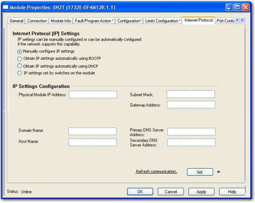
Internet Protocol Tab
1. To configure your IP settings, click the Internet Protocol tab. This tab is
only available for editing when the device is online. To manually
configure your IP settings, specify the IP address in the Physical Module
IP Address field.
2. On other fields (Domain Name, Host Name, Primary DNS Server
Address, Secondary DNS Server Address), specify the corresponding
parameter. Click Set and then click OK.
Rockwell Automation Publication 1732E-UM005B-EN-E - February 2022 31Chapter 3 Configure Your Analog Input and Output Modules
Port Configuration Tab
To configure the Ethernet ports, click the Port Configuration tab.
This tab is only available for editing when the device is online.
To configure the ports:
To Then
Leave Auto-negotiate port speed and duplex checked.
Use the default port speed and duplex settings This setting determines the actual speed and duplex
setting.
Follow these steps.
1. Clear the Auto-negotiate port speed and duplex
checkbox.
Manually configure your port’s speed and duplex 2. From the Current Port Speed pull-down menu, choose a
settings port speed.
3. From the Current Duplex pull-down menu, choose the
appropriate Duplex value, that is, Half Duplex or Full
Duplex.
IMPORTANT Consider the following when you configure the module’s port settings:
• If the module is connected to an unmanaged switch, leave Auto-
negotiate port speed and duplex checked or the module will fail.
• If you are forcing the port speed and duplex with a managed switch, the
corresponding port of the managed switch must be forced to the same
settings or the module will fail.
32 Rockwell Automation Publication 1732E-UM005B-EN-E - February 2022Chapter 3 Configure Your Analog Input and Output Modules
Calibration Tab
The Calibration tab on the Module Properties dialog box lets you recalibrate
the module, if necessary. Calibration corrects any hardware inaccuracies on a
particular channel.
For detailed information about calibration, see Calibrate Your Modules on
page 53.
Rockwell Automation Publication 1732E-UM005B-EN-E - February 2022 33Chapter 3 Configure Your Analog Input and Output Modules
Edit Your 1732E-OF4M12R Studio 5000 Logix Designer application automatically creates module-defined
Configuration data types and tags when a module is created. This section describes how to
modify the default configuration for input modules.
Data types symbolically name module configuration, input and output data.
Tags let you provide each a unique name, such as where the user-defined data
type and slot reside on the controller. This information is used to
communicate data between the controller and module.
After you have set configuration for a module, you can review and change your
choices. You can change configuration data and download it to the controller
while online. This is called dynamic reconfiguration.
Your freedom to change some configurable features, though, depends on
whether the controller is in Remote Run Mode or Program Mode.
IMPORTANT Although you can change configuration while online, you must go
offline to add or delete modules from the project.
The editing process begins on the main page of Studio 5000 Logix Designer
application.
1. On the I/O Configuration tree for your project, right-click the name of
your module.
2. Select Properties. The Module Properties dialog appears and has the
following tabs available for configuration.
3. Click any of the tabs to edit the parameters for your module.
The next sections show you how to edit the different tabs in the Module
Properties dialog.
Tabs can be selected in any order. The following examples are for
instructional purposes.
34 Rockwell Automation Publication 1732E-UM005B-EN-E - February 2022Chapter 3 Configure Your Analog Input and Output Modules
General Tab
The General tab allows you to edit general properties such as Name, IP
Address, and Description for your module.
You also can edit Module Definition properties such as revision, electronic
keying, and data. To do so, click Change.
General Tab Field Description
Field Name Description
Series Specifies the module series.
Revision Specifies the module’s major and minor revision.
The electronic keying feature automatically compares the expected module, as
shown in the Studio 5000 Logix Designer application I/O Configuration tree, to the
physical module before I/O communication begins. You can use electronic keying to
help prevent communication to a module that does not match the type and revision
expected.
For each module in the I/O Configuration tree, the user-selected keying option
determines if, and how, an electronic keying check is performed.
Typically, three keying options are available:
• Exact Match
• Compatible Module (default value)
• Disable Keying
Exact Match is an electronic keying protection mode that requires the physical
Electronic Keying module and the module configured in the software to match according to vendor,
catalog number, major revision and minor revision.
Compatible Module indicates that the module determines whether to accept or
reject communication. Compatible Keying is the default setting. It allows the
physical module to accept the key of the module configured in the software,
provided that the configured module is one the physical module is capable of
emulating. The exact level of emulation required is product and revision specific.
Disable Keying indicates the keying attributes are not considered when attempting
to communicate with a module. Other attributes, such as data size and format, are
considered and must be acceptable before I/O communication is established. With
Disabled Keying, I/O communication may occur with a module other than the type
specified in the I/O configuration tree with unpredictable results. We generally do
not recommend using Disabled Keying.
Available options are Data and Listen Only, with Data as default.
Calibration and Configuration options are not available for Listen Only option.
Listen Only specifies a dependent connection where a device receives inputs from
the target device, but does not send configuration data with the target device. A
Connection Listen Only connection only functions properly when another non-Listen Only
connection exists to the same target device. A Listen Only connection does not send
outputs; it only receives inputs. You can specify multiple Listen Only connections to
the target device from different originators.
Rockwell Automation Publication 1732E-UM005B-EN-E - February 2022 35You can also read