Assessing Changes in Dielectric Properties Due to Nanomaterials Using a Two-Port Microwave System - MDPI
←
→
Page content transcription
If your browser does not render page correctly, please read the page content below
sensors
Article
Assessing Changes in Dielectric Properties Due to
Nanomaterials Using a Two-Port Microwave System
Mohammed Rahman 1 , Rachita Lahri 1 , Syed Ahsan 2 , Maya Thanou 1
and Panagiotis Kosmas 2, *
 1    Institute of Pharmaceutical Sciences, King’s College London, Strand, London WC2R 2LS, UK;
      mohammed.3.rahman@kcl.ac.uk (M.R.); rachita3.lahri@gmail.com (R.L.); maya.thanou@kcl.ac.uk (M.T.)
 2    Faculty of Natural and Mathematical Sciences, King’s College London, Strand, London WC2R 2LS, UK;
      sayyed.n.ahsan@gmail.com
 *    Correspondence: panagiotis.kosmas@kcl.ac.uk

 Received: 24 August 2020; Accepted: 30 October 2020; Published: 31 October 2020

 Abstract: Detecting changes in the dielectric properties of tissues at microwave frequencies can offer
 simple and cost effective tools for cancer detection. These changes can be enhanced by the use of
 nanoparticles (NPs) that are characterised by both increased tumour uptake and high dielectric
 constant. This paper presents a two-port experimental setup to assess the impact of contrast
 enhancement on microwave signals. The study focuses on carbon nanotubes, as they have been
 previously shown to induce high microwave dielectric contrast. We investigate multiwall carbon
 nanotubes (MWNT) and their -OH functionalised version (MWNT-OH) dispersed in tissue phantoms
 as contrast enhancing NPs, as well as salt (NaCl) solutions as reference mixtures which can be easily
 dissolved inside water mixtures and thus induce dielectric contrast changes reliably. MWNT and
 MWNT-OH are characterised by atomic force microscopy, and their dielectric properties are measured
 when dispersed in 60% glycerol–water mixtures. Salt concentrations between 10 and 50 mg/mL
 in 60% glycerol mixtures are also studied as homogeneous samples known to affect the dielectric
 constant. Contrast enhancement is then evaluated using a simplified two-port microwave system to
 identify the impact on microwave signals with respect to dielectric contrast. Numerical simulations
 are also conducted to compare results with the experimental findings. Our results suggest that this
 approach can be used as a reliable method to screen and assess contrast enhancing materials with
 regards to a microwave system’s ability to detect their impact on a target.

 Keywords: microwave imaging; nanoparticles; contrast enhancement

1. Introduction
     Microwave tomography (MWT) and imaging (MWI) are currently being developed for various
applications [1–3]. In breast cancer detection, for example, MWI is currently tested using both
qualitative (radar-based) and quantitative (tomography) techniques. MWI systems utilise non-ionising,
low power microwaves, and have the potential to be inexpensive, portable, and produce images in
real (or quasi-real) time. Clinical studies such as those of the Dartmouth MWT system [3] and the
MARIA M4 radar-based imaging system [4] indicate that MWI has potential to provide a reliable and
safe alternative tumor detection method.
     Various dielectric spectroscopy studies [5–9] of excised healthy and cancerous tissues have
suggested that the dielectric contrast between (dense) healthy and cancerous breast tissue can be
as low as 10%. These tissue characterisation studies show variation in dielectric measurements,
which can be explained by the sample preparation and measurement technique. The accuracy
of dielectric spectroscopy [10,11] and the impact of the tissue sample’s hydration level [12,13]

Sensors 2020, 20, 6228; doi:10.3390/s20216228                                 www.mdpi.com/journal/sensors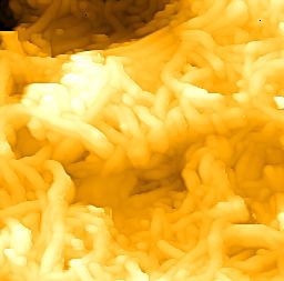
Sensors 2020, 20, 6228                                                                              2 of 19

complicate further the goal of assessing tissue contrast based on dielectric spectroscopy measurements.
Indeed, tissue hydration can pose challenges in producing consistent dielectric measurements, as it can
affect the complex dielectric constant. For example, dielectric measurements of excised rodent tissues
(fat and muscle) were recently compared with in vivo measurements and showed a correlation between
dehydration and reduced dielectric properties [14]. Dielectric profiles of excised rodent liver tissues
were taken over time in [15], which showed a similar trend of dielectric properties being reduced
because of dehydration. Dielectric characterisations of breast cancer cells have also been conducted to
further assess the dielectric components in the tumours [16,17].
      Contrast agents are used widely in imaging and screening techniques to overcome issues of
poor low contrast between healthy and malignant tissue [18]. Contrast-enhanced MW imaging
has been studied in clinical scenarios, but mostly with hypothetical simulation models [19,20].
Clinically accepted contrast agents must be biocompatible and chemically modified for intravenous
delivery. Their size should be suitable to take advantage of the enhanced permeation and retention
effect observed in solid tumours, and they should induce detectable dielectric contrast for radar and
tomographic MWI techniques. Moreover, contrast agents should show preferential accumulation to
the tumours and achieve high contrast concentration in the tumour region. To this end, the contrast
agents can be decorated with specific antibodies for cancer biomarkers, such as trastuzumab antibodies
in the case of breast cancer [21,22].
      Various studies have looked at the possibility of microwave contrast enhancement for
biocompatible agents such as functionalised iron oxide NPs [23]. Dispersed iron oxide NPs have
shown magnetic contrast which can be detected in phantoms using a microwave setup coupled with
a magnet to turn on and off the polarizing magnetic field [24–26]. Recent work on metal-based
nanomaterials suggests that ferrite and titanate NPs may have a strong effect on the dielectric
properties of tissues. These NPs are characterised by a more biocompatible profile relative to carbon
nanotubes [27]. Gold nanoparticles have also been proposed as a promising biocompatible alternative
to other metal contrast agents, but previous studies have shown very limited ability on affecting the
dielectric constant of water [28,29].
      Our group has identified highly dispersible and biocompatible zinc ferrite NPs as agents
that may induce detectable dielectric contrast in a background medium at microwave frequencies.
These particles may be also able to increase the conductivity of the targeted region, suggesting
potential to be used as thermal agents for localised microwave hyperthermia [30]. PEGylated zinc
oxide NPs have also been shown to induce dielectric contrast in aqueous suspensions, and their
resulting dielectric properties are heavily dependent on the molecular weight of the polyethylene
glycol [31,32]. Reduced graphene oxide (RGO) and modified RGO with zinc oxide nanowires
(ZnO/RGO) have also shown high dielectric properties at higher frequencies, between 8.0 and
12.0 GHz [33,34]. Prior to these studies, carbon nanotubes (CNTs) were proposed as nanomaterials that
can induce microwave dielectric contrast. Standard CNTs were shown to exhibit dielectric contrast
over ∼40% and conductivity contrast of ∼80% [35], and experiments of dispersing CNTs into breast
tumour mimicking phantoms have been reported [36]. Moreover, it has been shown that purification
method and solvent choice have significant affect on the CNTs dielectric properties [37,38].
      CNTs have unique electrical properties, which can be attributed to their distinctive structure [39].
As such, they have been characterised in the microwave spectrum to identify their benefits for
several applications. They have also been assessed as potential microwave nano-absorbers and have
been modified in several ways to enhance these properties [40]. For example, single-walled carbon
nanotubes (SWCNTs) filled with cobalt nanoparticles and dispersed in cured epoxy resin has shown
enormous dielectric and magnetic contrast with respect to the controls between 2.0 and 18.0 GHz,
as measured by the coaxial transmission line technique [41]. Similarly, multi-walled carbon nanotubes
(MWNTs) filled with samarium oxide nanoparticles have shown significant dielectric contrast in the
order of ∼40% compared with pristine MWNTs in the range of 2.0–14.0 GHz [42]. The microwave
characterisation of Nickle-filled MWNTs dispersed in paraffin also demonstrated that doubling the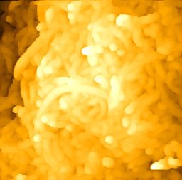
Sensors 2020, 20, 6228                                                                               3 of 19

concentration of the composite increases significantly the permittivity and permeability properties
between 2.0 and 18.0 GHz [43]. Iron filled MWNTs dispersed in olefin at 20%wt ratio have shown
extreme dielectric loss compared with basic MWNTs, between 8 and 18 GHz [44,45]. Iron oxide NPs
attached to the outer surface of MWNTs exhibit varying microwave absorption properties, when mixed
with/out poly(N-vinyl-2-pyrrolidone) dispersant [46]. Fusion between CNTs and other metallic and
semiconductor materials offer higher microwave absorption capacities [47,48].
      Based on the above, this work uses MWNTs as a nanomaterial reference for assessing the
impact of contrast enhancement at microwave frequencies. In particular, our aim is to suggest a
methodology which can assess whether the impact of dielectric contrast enhancement can be detected
in a MWI system. Our results can serve as reference for future studies of more biocompatible but
less strong contrast-enhancing agents such as the PEGylated zinc oxide NPs that we have proposed
recently [31,32]. To this end, we have employed an experimental two-port microwave measurement
system, basic and functionalised multi-walled carbon nanotubes (MWNT and MWNT-OH) as contrast
agents, and varying concentrations of salt mixed in 60% glycerol as materials with the potential of
altering the dielectric constant. Salt has two main functions in this study: first, to induce significant
change in dielectric properties as observed in previous spectroscopy studies of saline [49] and
aqueous-based materials [50]. Second, salt dissolves in aqueous solutions and is considered isotropic,
thus presenting a reliable means of inducing consistent dielectric properties that depend on its salt
concentration in the 60% glycerol water mixtures.
      Our microwave experiments employ the same bi-static (two-port) microwave (2PMW) setup as
in [51], but for a very different purpose. While experiments in [51] were set up to test reconstructions of
high contrast dielectric targets, our focus here is to assess the impact of dielectric contrast enhancement
on a potential MWI system for medical applications. In a clinical scenario, the contrast-enhanced
target will represent a small region inside a lossy background medium, and the interaction of these
two “regions” will have a significant impact on the measured signals. The lossy surrounding region
will cause significant attenuation in the signal scattered by the contrast-targeted region, resulting
in a very weak signal which may not be detectable by our measurement apparatus (VNA) for
certain receiver positions (Rx) relative to the transmitting antenna (Tx). To answer these questions
without over-complicating the measurement, we chose to use an imaging tank with a liquid phantom
resembling fatty human tissue, a cylindrical target filled with a liquid phantom resembling malignant
tissue with and without contrast agents, four Tx/Rx pairs, and antennas that can be realistic candidates
for microwave medical imaging [51].
      We note that our approach is more complicated and prone to errors than a direct measurement
with two antennas facing the contrast-enhanced liquid phantom, which could produce a more reliable
method to assess the impact of contrast enhancement on the microwave signals transmitted and
received by the antenna pair. Our choice of a more complicated setup is motivated by our interest in
studying how contrast enhancement can impact the signals produced and processed by a multi-view
MWI system that we are currently developing. Our MWI system is intended to exploit signals that can
be either mostly due to back-scatter from the target at oblique angles, or due to signals transmitted
through the background medium and the target. The 2PMW setup with four Tx/Rx pairs studied in
this paper serves this purpose as an initial investigation. Future work should extend this study to a fully
multi-static system, as well as compare these findings to more robust measurements with an antenna
pair only. This comparison would answer the question on how the impact of contrast enhancement
measured by the antenna pair is translated to a system designed for a practical MWI application.
      To evaluate the impact of contrast enhancement for our imaging prototype under development,
we have selected a NP concentration of 2 mg/mL for the CNTs in agreement with previous
studies [32,52]. We also note that carbon nanotubes are known to be toxic and non-biocompatible.
Multiple pathways of administration have shown cytotoxic effects through in vitro and in vivo [53,54].
Recent in-vivo studies have shown success in making CNTs biocompatible for anti-cancer drugs [55,56]
and bone regeneration [57]. However, these studies do not administer the NPs intravenously, and thus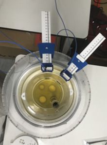
Sensors 2020, 20, 6228 4 of 19
delivery to the targeted location without damaging other areas remains a challenge. Despite these
limitations, the deployment of CNTs as contrast agents for our experiments is necessary as a reference
for assessing the NP agent’s impact on microwave signals.
Our phantoms comprise only a background medium with a low dielectric constant (safflower
oil) and a cylindrical target with a high dielectric constant (mixture of 60% glycerol and RO water),
where the NPs or salt are introduced. Specifically, the dielectric constant for safflower oil is 2.9 at
1.0 GHz, which is comparable to the dielectric constant of fatty breast tissue in this frequency
range [5,6,58]. The mixture of 60% glycerol and RO water has a high dielectric constant (56.6 at
1.0 GHz) and allows better dispersibility of the NPs. This high dielectric constant liquid can serve as
initial phantom for tumour tissue, for which the dielectric constant varies between 50 and 60 [59–61].
To ensure that results are conclusive and not due to possible measurement errors, we have performed
realistic simulations of our experiments which have reaffirmed our experimental findings.
2. Materials and Methods
2.1. Atomic Force Microscopy (AFM)
MWNT and MWNT-OH aqueous suspensions were prepared in water at 2 mg/mL, and 100 µL
was pipetted on the glass microscopic slide which was dried using nitrogen gas. Images were taken
using the Bruker icon dimension atomic force microscope (Bruker Corporation, Billerica, MA, USA),
with the standard tapping mode applied. The scanning area started at a large region of 10.0 × 10.0 µm
and was decreased to a smaller region of interest (ROI) of 1.7 × 1.7 µm. The scan rate decreased from
0.9 Hz to 0.7 Hz as the scan size decreased, to improve image quality. The software uses a PID feedback
system to improve the trace and retrace signals. To improve the reliability of image acquisition, the scan
angle of the probe is altered from 0◦ to 90◦ and the raster scan for the images is repeated. This is a
confidence check to observe any artifacts produced because of particles stuck onto the cantilever.
2.2. Dielectric Characterisation
Dielectric characterisation was recorded using a an open-ended coaxial cable probe kit (85070E)
(Keysight Technologies, Santa Rosa, CA, United States) and a performance vector analyser PNA
E8362B (Keysight Technologies, Santa Rosa, California, United States). The slim-form probe was
calibrated using three known dielectric materials: air, short block (conductive elastomer that mimics
electrical properties of metal), and reverse osmosis purified (RO) water. The minimum and maximum
frequencies for the dielectric measurements was set to 1.0–4.0 GHz, respectively. This frequency
range is motivated by our aim to compare the impact of changes in dielectric contrast with the
resulting changes in the microwave signals recorded by our experimental setup, which operates in
the range of 1.0–4.0 GHz [51]. The probe operates in a much wider range, between 0.5 and 50 GHz,
and needs a minimum of 5 mm sample thickness for measurements. We note that ideal measurements
require that the probe is immersed into an isotropic medium. The complex permittivity for a given
σ(ω )
material is e∗ (ω ) = e0 (ω ) − je00 (ω ) = e0 (ω ) − j ωe0 , and is measured by the dielectric probe kit
through measurement of e0 (ω ) and e00 (ω ). The dielectric constant e0 (ω ) is the real part of the complex
permittivity. The effective conductivity σ (ω ) can be easily calculated from the loss index e00 (ω ) for a
given angular frequency ω, where e0 is the dielectric constant of free space.
2.3. Microwave Experimental Method
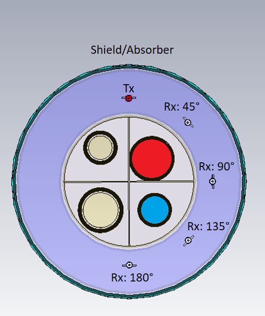
The microwave experimental system to assess the impact of contrast agents is shown in Figure 1,
and is comprised of two concentric cylindrical tanks with an inner and outer radius of 60 and 100 mm,
respectively. The tank is made of acrylic, and the height of the inner and outer tanks are 300 and
200 mm, respectively. The base of the inner tank contains a target holder designed to support four
liquid-filled targets at fixed locations. Two targets of the same height of 300mm but different radii are
used in this study, Target 1 (T1) with radius r = 15 mm, and Target 2 (T2) with r = 10 mm. The targets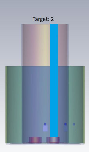
Sensors 2020, 20, 6228                                                                                          5 of 19

are positioned in a custom acrylic cap which is attached on top of the inner tank at different locations.
Outside the target cylinder, the inner tank is filled with safflower oil which has very low dielectric
properties and corresponds to a homogeneous high adipose (fatty) tissue layer. The outer tank is filled
with a 9/1 mixture of glycerol and RO water, in which the transmitting and receiving antenna are
immersed. This mixture has a high loss tangent, and is chosen to minimise multipath signals [51].
To minimise multipath signals and external interference further, we used a microwave absorbing sheet
(1mm thickness and height of 150 mm) around the periphery of the 200 mm tank and covered the
external face with aluminium foil.

            (a) T1                  (b) T2                   (c) 3-D model                  (d) Experiment

      Figure 1. The modelled 3-D simulated and experimental configuration used to observe the transmitted
      signal differences caused by different dielectric targets: Drawings of (a) Target T1 (r = 15mm), (b) Target
      T2 (r = 10mm), and (c) the 3-D model used in simulations; (d) Photo of the experimental setup shown
      in these drawings.

     The system uses printed monopole antennas that operate in the frequency range between 1.0 and
3.0 GHz when immersed into the glycerol–water mixture [51]. The antennas are designed with a funnel
shaped patch constructed on a FR-4 substrate and a partial ground. These antennas were designed to be
small with a 180 mm2 surface area, which may help prevent multipath signals. Also, smaller antennas
allow more elements in an antenna array, hence increasing the accuracy of received data. The SMA
connectors were soldered on to the bottom face of the antennas and were joined to flexible coaxial cables
with a dedicated internal O-ring, which prevented the coupling liquid leaking into the connectors.
L-shaped calipers were used to position the antennas and move radially to take concentric scattering
measurements. The experimental process used a fixed transmitter and a receiver which was radially
positioned between 45◦ and 180◦ with respect to the tank centre. For each target scenario, we measured
at four angles (45◦ , 90◦ , 135◦ , and 180◦ ), allocating a time interval for the forward scattering data
to settle before restarting the average, and repeated the process 5 times to assess the variability in
our measurements. The antennas were connected to a two-port vector network analyser (VNA),
and S-parameter (Sθ ) measurements were recorded between 1.0 and 3.0 GHz with 201 sample points.
The intermediate frequency (IF) was 200 Hz and the average factor set to 10.
     For every angle, the cylindrical target T1 (or smaller target T2) was filled with different materials
prior to taking measurements at the next interval. These included samples of salt concentrations
(10–50 mg/mL) dissolved in 60% glycerol water mixture, which were used as a reference in this
study to investigate the correlation between dielectric contrast and transmitted signals difference.
Furthermore, MWNT and MWNT-OH of diameter 20–30 nm and length 10–30 µm (Cheap Tubes,
Grafton, VT, USA) at a concentration of 2 mg/mL dispersed in a 60% glycerol–water mixture were
used as targets to correlate their contrast enhancement measured from dielectric spectroscopy with
their impact on the signals recorded by the receiving antenna. The specific concentration was selected
because of previous nanoparticle spectroscopy studies showing large dielectric contrast [32,35].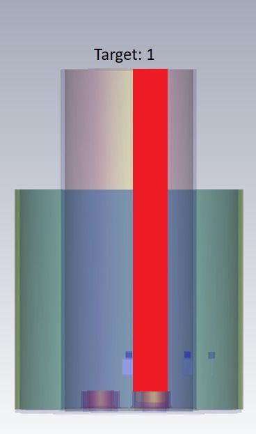
Sensors 2020, 20, 6228                                                                                 6 of 19

     We also simulated these experiments in CST Microwave Studio, in order to study the impact of
the contrast enhancement on transmitted signals in the absence of measurement errors. The simulated
2PMW setup was imported from STL files preserving the geometry of the experiment as shown in
Figure 1. The phantom liquids with or without the contrast agents were assigned dielectric properties
based on their dielectric spectroscopy measurements, while the acrylic used to model the imaging tank
was assigned dielectric values taken from CSTs library of materials. The antennas were fully modelled
as in [51]. Open space boundary conditions were used to terminate the computational domain outside
the imaging tank. CSTs frequency solver was used with tetrahedral meshing, and with an initial
mesh size of 105 cells which evolved to 106 cells after adaptive mesh refinement with a minimum and
maximum of four and eight passes, respectively.
     To quantify this impact, we plot (as function of frequency) the difference in transmitted signal
for a given measurement angle, ∆Sθ = |Sθ,homog − Sθ,contrast |, where Sθ,homog and Sθ,contrast are the
transmission coefficients at each receiver location in the absence (target filled with 60% glycerol–water
mixture only) or presence of the contrast agent (target filled with the MWNT or salt solutions).

3. Results

3.1. Size Characterisation for MWNT and MWNT-OH NPs
     AFM images are shown in Figure 2 and suggest that these nanomaterials have a tube/rod-like
structure in nature. Moreover, analysis of the AFM micrographs gave an average diameter tube size
of 32nm and 26nm for MWNT-OH and MWNT, respectively, which agrees with the width stated
by the manufacturers (see Table 1). It was difficult to measure the length of CNTs because of their
entanglement. However, the diameter of the CNTs obtained agreed with stated manufacturer size.

                         500 nm                           500 nm

                                  (a) MWNT                      (b) MWNT-OH

      Figure 2. Atomic force microscopy (AFM) images of (a) MWNT and (b) MWNT-OH at a concentration
      of 2 mg/mL with scanned dimension of 1.7 µm × 1.7 µm.

      Table 1. The manufacturer-stated and AFM-calculated width of basic and functionalised multi-walled
      carbon nanotubes (MWNT and MWNT-OH, respectively).

                               CNT        Stated Width (nm)     AFM Width (nm)
                             MWNT               20 – 30             26.4 ± 5.1
                            MWNT-OH             20 – 30             32.1 ± 4.7
Sensors 2020, 20, 6228 7 of 19
3.2. Dielectric Spectroscopy Measurements
Dielectric spectroscopy measurements with the probe kit were used to determine the level of
dielectric contrast caused by the salt or MWNTs. As explained in the Methodology section, the dielectric
properties were characterised between 1.0 and 4.0 GHz. A mixture consisting of 60% glycerol and 40%
water was chosen as the background liquid in which the agents were dispersed, as our experiments
have shown that this mixture improves the stability of colloidal dispersions. Furthermore, the dielectric
properties of 60% glycerol–water mixture are similar to breast tumour tissue with a value of 56.6 at
1.0 GHz, which makes this choice relevant to a realistic scenario of detecting contrast agents in the
tumour area.
Figure 3 plots the dielectric constant and conductivity vs. frequency for different concentrations of
our contrast agents suspended/dissolved in 60% glycerol–water mixtures. As expected, the addition
of salt decreases the dielectric constant over the whole frequency range, and this decrease is monotonic
with respect to salt concentrations between 10–50 mg/mL. Conversely, the conductivity is increased
for frequencies up to 2.0 GHz. At 1.0 GHz, for example, the dielectric constant drops from 56.4 for 60%
glycerol to 44.8 for 60% glycerol with 50mg/mL dissolved salt. The effective conductivity increase
is 20.1%, 39.7%, and 68.0% for 10, 20 and 50 mg/mL salt concentration, respectively. The increase in
conductivity at lower frequencies is dependent on free drift ions while dielectric loss is prominent [62]
at higher frequencies. In particular, the dielectric loss is masked at lower frequencies due to ionic
conduction, but becomes more noticeable as frequency increases [62,63].
The dielectric values plotted in Figure 3 are averaged over 10 measurements for each salt solution
sample. The measurement variations (σstd ) in all samples are small compared to the measured values.
The standard deviation of the dielectric constant of the 60% glycerol mixture at 1.0 GHz is ±0.005.
Homogeneous liquids tend to show small measurement variation due to isotropy of the material.
The σstd of the dielectric constant at 1.0 GHz for saline samples are ±0.054, ±0.034, and ±0.027 for
ascending concentrations of salt. The measurement variation increased with the addition of salt in
these solutions and this level of error is similar throughout the frequency ranges, suggesting that the
increase in salt (and thus in conductivity) may lead in an increase in the measurement uncertainty.
As discussed in the Introduction, CNTs have been previously proposed as contrast agents for
microwave imaging, and their dielectric properties have been measured when dispersed in liquid or
solid phantoms. However, there is no study that looks at the effect of functionalisation. MWNTs are
functionalised to increase their water association, which leads to better dispersion and thus more
biocompatibility. The dielectric properties of MWNTs dispersed in 60% glycerol at 2 mg/mL are
presented in Figure 3c,d. Both samples show significant increase in the dielectric contrast with respect
to the background 60% glycerol–water mixture over the measured frequency range, and the increase
is more pronounced for higher frequencies (e.g., 12.93% and 17.41% for MWNT and MWNT-OH,
respectively, at 1.0 GHz, and 67.79% and 60.47% at 4.0 GHz). Similar to the plots for salt concentrations,
the dielectric values plotted in Figure 3 are averaged over 10 measurements of MWNT and MWNT-OH
samples, and the measurement variations (σstd ) in all samples are small compared to the measured
values. The σstd of the dielectric constant at 1.0 GHz for the MWNT and MWNT-OH NP samples
are ±0.043 and ±0.092, respectively. At 4.0 GHz, the σstd of the dielectric constant for MWNT and
MWNT-OH samples are ±0.044 and ±0.022, respectively.
The hydroxylated NPs show slightly larger contrast in comparison to the unfunctionalised
multi-wall NPs up to 2.0 GHz, but this trend is reversed for higher frequencies. Dielectric properties
are increased by functionalised MWNTs because dispersion properties of MWNTs are improved in 60%
glycerol. At higher frequencies, however, it appears that more pristine CNTs lead to higher dielectric
constant. The large contrast increase suggests that these NPs can impact transmitted and received
signals in a microwave system.Sensors 2020, 20, 6228 8 of 19
55 10mg/mL
(S/m)
20mg/mL 5
50 50mg/mL
60% Glycerol
Dielectric Constant
45
Effective Conductivity
4
40
3
35
30 10mg/mL
2 20mg/mL
25 50mg/mL
60% Glycerol
1
1 1.5 2 2.5 3 3.5 4 1 1.5 2 2.5 3 3.5 4
Frequency (GHz) Frequency (GHz)
(a) Dielectric Constant e (b) Effective Conductivity σ
65 MWNT 7
(S/m)
MWNT-OH
60 60% Glycerol 6
Dielectric Constant
55
Effective Conductivity
5
50
4
45
3
40
35 2 MWNT
MWNT-OH
30 1 60% Glycerol
1 1.5 2 2.5 3 3.5 4 1 1.5 2 2.5 3 3.5 4
Frequency (GHz) Frequency (GHz)
(c) Dielectric Constant e (d) Effective Conductivity σ
Figure 3. Microwave dielectric properties of the target materials used for dielectric contrast
enhancement. (a) Dielectric constant, and (b) effective conductivity of 60% glycerol mixed with a range
(10 mg/mL–50 mg/mL) of salt concentrations. (c) Dielectric constant, and (d) and effective conductivity
of 60% glycerol suspensions with basic (MWNT) and functionalised (MWNT-OH) multi-walled carbon
nanotubes at 2 mg/mL. The average values over 10 measurements (n = 10) of each salt solution and
NP dispersion samples are plotted with ±1 σstd .
3.3. Microwave System Measurements
As detailed in the Methodology section, microwave measurements were taken with our 2PMW
setup, where the transmitter was at a fixed position and the receiver was positioned at angles 45◦ –180◦
relative to the transmitter. Different-diameter cylinders T1 and T2 (see Figure 1) were used as targets
to understand how the volumetric difference affected the system response. The 60% glycerol–water
mixture was used as the background, “non-agent” case.
3.3.1. Salt (NaCl)
Salt concentrations between 10 and 50mg/mL dissolved in 60% glycerol were used inside either
the T1 or T2 target cylinders to correlate their dielectric contrast effect with the impact on microwave
signals recorded by the 2PMW system. The difference between the background (60% glycerol) and
the inclusion (60% glycerol and salt concentration) was calculated at each receiver location. Figure 4
shows the difference in received signal strength at each receiver position due to the different salt
concentrations, for both experimental and simulated data.Sensors 2020, 20, 6228 9 of 19
10-5 10-5
1.5
1
1 0.8
| S45 °|
| S45 °|
0.6
0.5 0.4
0.2
0 0
1 1.5 2 2.5 3 1 1.5 2 2.5 3
Frequency (GHz) Frequency (GHz)
(a) 45◦ (Sim) (b) 45◦ (Exp)
10-4 10-4
3 4
Glycerol(60%) - 10mg/mL Glycerol(60%) - 10mg/mL
Glycerol(60%) - 20mg/mL Glycerol(60%) - 20mg/mL
Glycerol(60%) - 50mg/mL 3
Glycerol(60%) - 50mg/mL
2
| S90 °|
| S90 °|
2
1
1
0 0
1 1.5 2 2.5 3 1 1.5 2 2.5 3
Frequency (GHz) Frequency (GHz)
(c) 90◦ (Sim) (d) 90◦ (Exp)
10-4 10-4
3 2
1.5
2
| S135°|
| S135°|
1
1
0.5
0 0
1 1.5 2 2.5 3 1 1.5 2 2.5 3
Frequency (GHz) Frequency (GHz)
(e) 135◦ (Sim) (f) 135◦ (Exp)
10-4 10-4
1.5 2
1.5
1
| S180°|
| S180°|
1
0.5
0.5
0 0
1 1.5 2 2.5 3 1 1.5 2 2.5 3
Frequency (GHz) Frequency (GHz)
(g) 180◦ (Sim) (h) 180◦ (Exp)
Figure 4. Difference in received signal strength between “no-target” and “target T1” cases, plotted for
each receiver position against frequency. T1 is filled with salt concentrations between 10 and 50mg/mL
dissolved in 60% glycerol. The simulated (left) and experimental (right) signal differences are plotted
between 1.0 and 3.0 GHz, which is the operational frequency range for the employed antennas.
These results confirm that larger concentrations of salt cause stronger signal differences at the
lower end of the frequency spectrum, where the antenna operates optimally and signal losses are lower.
Impact on higher frequencies is difficult to detect with these experiments, due to the very low signal
levels. For example, the experimental signal difference at 45◦ shows a maximum value of −98.4 dB,
which is close to the noise level of the VNA. For the more accurate lower frequency range of up to 2 GHz,Sensors 2020, 20, 6228 10 of 19
receiver angles 90◦ –180◦ show that the signal difference increases as the salt concentration increases,
particularly for the highest concentration of 50 mg/mL. The level of experimentally measured signal
difference agrees well with the simulation results, although the two signals are very different. There are
however cases of fairly good agreement between the measured and simulated signals, such as in the
range 1.2–1.5 GHz for the 135◦ location.
The received signal difference using the smaller target cylinder, T2, is plotted in Figure 5 for the
different receiver positions. In this case, ∆S45◦ (Figure 5a) is less than −90.0dB. The signal difference at
position 90◦ peaks around −80.0dB for the 50mg/mL salt target, for both experimental and simulation
data. Simulated differences at position 90◦ do show a clear monotonic behaviour between 1.0 and
1.5 GHz, but this is less evident in the experimental results, and particularly for the two lower NaCl
concentrations. The 10mg/mL experimental difference at position 90◦ is unexpected for both T1 and
T2 targets. This is in contrast to the simulated difference at 90◦ , where again a monotonic behaviour
is observed.
Significant signal differences for both experimental and simulated signals are observed for ∆S135◦ ,
with a clear monotonic dependence on salt concentrations. The peak experimental values S135◦ are
−79.2 dB, −75.9 dB, and −73.2 dB for 10 mg/mL, 20 mg/mL, and 50 mg/mL salt concentrations,
respectively, at 1.3 GHz. Experimental signal differences ∆S180◦ are concentration-dependent between
1.0 and 1.4GHz, with a maximum contrast of −80.0 dB for the 50 mg/mL salt target.
3.3.2. MWNT and MWNT-OH Suspensions
The signal differences due to the salt concentrations analysed in the previous section showed
that a measured dielectric contrast decrease in the range of 12–26% can have a detectable impact on
received signal strength measured by the 2PMW system. We now repeat this analysis to observe the
effect of the MWNTs suspensions in the 60% glycerol background for targets T1 and T2.
Simulated and experimental signal differences for MWNT and MWNT-OH dispersions in target
T1 are plotted in Figure 6. Similar to the cases with salt, the receiver position at 45◦ is affected the least
by the contrast, with experimental and simulated signal differences showing a maximum contrast
of −84.4 dB and −97.1 dB, respectively. The simulated ∆S90◦ has a maximum value of −67.8 dB
(MWNT), while the maximum experimental ∆S90◦ is −70.5 dB. The signals of ∆S90◦ shows good
agreement between simulation and experiment in 1.0–1.5 GHz, although the simulated MWNT-OH
target response is lower in magnitude. MWNT and MWNT-OH suspensions show a maximum
contrast of −68.0 dB and −70.5 dB for position 135◦ , respectively, and good agreement is observed
for ∆S135◦ between simulation and experiment in the range 1.5–2.0 GHz, but not between 1.0 and
1.5 GHz. Experimental and simulated ∆S180◦ show good agreement, although the peak value is larger
for the experiment.
The simulated and experimental signal differences for MWNT and MWNT-OH suspension in
target T2 are plotted in Figure 7. The simulated ∆S90◦ shows a maximum contrast of −80.5 dB, however
the experimental ∆S90◦ shows a significantly larger signal difference of −69.6 dB. The experimental
∆S135◦ shows a large difference due to the MWNT suspension, with a maximum of −67.1dB and
−67.5 dB for MWNT and MWNT-OH suspensions, respectively. In simulation, the maximum
difference at position 135◦ for MWNT and MWNT-OH targets are −72.0 dB and −73.7 dB, respectively.
The simulated difference is lower in magnitude and the peak is shifted in frequency in comparison with
the experimental signal difference. The experimental and simulated transmission contrast observed at
∆S180◦ have some agreement between 1.2 and 2.5 GHz, however the experimental difference has large
variation between frequency points.Sensors 2020, 20, 6228 11 of 19
10-5 10-5
3 3
Glycerol(60%) - 10mg/mL Glycerol(60%) - 10mg/mL
Glycerol(60%) - 20mg/mL Glycerol(60%) - 20mg/mL
Glycerol(60%) - 50mg/mL Glycerol(60%) - 50mg/mL
2 2
| S45 °|
| S45 °|
1 1
0 0
1 1.5 2 2.5 3 1 1.5 2 2.5 3
Frequency (GHz) Frequency (GHz)
(a) 45◦ (Sim) (b) 45◦ (Exp)
10-4 10-4
1 1
0.8 0.8
| S90 °|
| S90 °|
0.6 0.6
0.4 0.4
0.2 0.2
0 0
1 1.5 2 2.5 3 1 1.5 2 2.5 3
Frequency (GHz) Frequency (GHz)
(c) 90◦ (Sim) (d) 90◦ (Exp)
10-4 10-4
2 2.5
2
1.5
| S135°|
| S135°|
1.5
1
1
0.5
0.5
0 0
1 1.5 2 2.5 3 1 1.5 2 2.5 3
Frequency (GHz) Frequency (GHz)
(e) 135◦ (Sim) (f) 135◦ (Exp)
10-4 10-4
1
1 0.8
| S180°|
| S180°|
0.6
0.5 0.4
0.2
0 0
1 1.5 2 2.5 3 1 1.5 2 2.5 3
Frequency (GHz) Frequency (GHz)
(g) 180◦ (Sim) (h) 180◦ (Exp)
Figure 5. Difference in received signal strength between “no-target” and “target T2” cases, plotted for
each receiver position against frequency. T2 is filled with salt concentrations between 10–50 mg/mL
dissolved in 60% glycerol. The simulated (left) and experimental (right) signal differences are plotted
between 1.0–3.0 GHz, which is the operational frequency range for the employed antennas.Sensors 2020, 20, 6228 12 of 19
10-5 10-5
1.5 6
5
1
| S45 °|
| S45 °|
4
3
0.5
2
0 1
1 1.5 2 2.5 3 1 1.5 2 2.5 3
Frequency (GHz) Frequency (GHz)
(a) 45◦ (Sim) (b) 45◦ (Exp)
10-4 10-4
5 3
Glycerol(60%) - MWNT Glycerol(60%) - MWNT
4 Glycerol(60%) - MWNT-OH Glycerol(60%) - MWNT-OH
2
| S90 °|
| S90 °|
3
2
1
1
0 0
1 1.5 2 2.5 3 1 1.5 2 2.5 3
Frequency (GHz) Frequency (GHz)
(c) 90◦ (Sim) (d) 90◦ (Exp)
10-4 10-4
2.5 3
2
2
| S135°|
| S135°|
1.5
1
1
0.5
0 0
1 1.5 2 2.5 3 1 1.5 2 2.5 3
Frequency (GHz) Frequency (GHz)
(e) 135◦ (Sim) (f) 135◦ (Exp)
10-4 10-4
1.5 3
1 2
| S180°|
| S180°|
0.5 1
0 0
1 1.5 2 2.5 3 1 1.5 2 2.5 3
Frequency (GHz) Frequency (GHz)
(g) 180◦ (Sim) (h) 180◦ (Exp)
Figure 6. Difference in received signal strength between “no-target” and “target T1” cases, plotted for
each receiver position against frequency. T1 is filled with MWNT and MWNT-OH colloidal suspensions
with a concentration of 2 mg/mL dispersed in 60% glycerol. The simulated (left) and experimental
(right) signal differences are plotted between 1.0–3.0 GHz, which is the operational frequency range for
the employed antennas.Sensors 2020, 20, 6228 13 of 19
10-5 10-5
1.5 6
Glycerol(60%) - MWNT
5 Glycerol(60%) - MWNT-OH
1
| S45 °|
| S45 °|
4
3
0.5
2
0 1
1 1.5 2 2.5 3 1 1.5 2 2.5 3
Frequency (GHz) Frequency (GHz)
(a) 45◦ (Sim) (b) 45◦ (Exp)
10-4 10-4
1 4
0.8
3
| S90 °|
| S90 °|
0.6
2
0.4
1
0.2
0 0
1 1.5 2 2.5 3 1 1.5 2 2.5 3
Frequency (GHz) Frequency (GHz)
(c) 90◦ (Sim) (d) 90◦ (Exp)
10-4 10-4
2.5 5
2 4
| S135°|
| S135°|
1.5 3
1 2
0.5 1
0 0
1 1.5 2 2.5 3 1 1.5 2 2.5 3
Frequency (GHz) Frequency (GHz)
(e) 135◦ (Sim) (f) 135◦ (Exp)
10-4 10-4
1.5 1.5
1 1
| S180°|
| S180°|
0.5 0.5
0 0
1 1.5 2 2.5 3 1 1.5 2 2.5 3
Frequency (GHz) Frequency (GHz)
(g) 180◦ (Sim) (h) 180◦ (Exp)
Figure 7. Difference in received signal strength between “no-target” and “target T2” cases, plotted for
each receiver position against frequency. T2 is filled with MWNT and MWNT-OH colloidal suspensions
with a concentration of 2 mg/mL dispersed in 60% glycerol. The simulated (left) and experimental
(right) signal differences are plotted between 1.0 and 3.0 GHz, which is the operational frequency range
for the employed antennas.Sensors 2020, 20, 6228 14 of 19
4. Discussion
4.1. Dielectric Spectroscopy Analysis
The contrast in conductivity due to the salt or the MWNTs is surprisingly lower than when these
are in water. Glycerol forms hydrogen bond networks when mixed in water, which has an unusual
increase in dielectric loss at higher frequencies, leading to a departure from Debye-type relaxations [64].
This phenomenon is called excess wing and is caused by glass forming materials. Depending on the
glycerol–water mixture ratio, interactions between glycerol–glycerol regions, water–water regions
and glycerol–water regions affect the dielectric relaxation [65]. This causes two overlapping dielectric
relaxations process; alpha(α) relaxation, which is caused by the glycerol–water and glycerol–glycerol
interactions, and beta(β)relaxations, which is caused by water–water interactions [66].
MWNTs are generally conductive because of delocalised electrons. These electrons can travel a
distance without being scattered, a phenomenon known as ballistic conduction. MWNTs are shown to
be ballistic conductors at room temperatures, with mean free paths of the order of tens of microns [67].
Longer and thicker CNTs ensure a better conduction pathway, hence larger dielectric properties are
observed with MWNTs. Also, there is an increase in space charge polarisation, due to the accumulation
of electrons at the surface, which has an additive effect [68].
4.2. Microwave System Analysis
We have built the 2PMW system as a simple tool to assess dielectric constant of phantoms with
and without contrast agents. Our approach relies on observations of the raw scattering data from
the 2PMW system, rather than attempting to reconstruct images from the system. Reconstructions
with limited view data are susceptible to various measurement and imaging model errors and would
require a more sophisticated system. In contrast, our approach can offer a simple way to assess the NPs
impact directly on signals similar to what a MWI system would record, rather than relying on dielectric
spectroscopy measurements which are not directly correlated with MWI measurements. Interpreting
these experimental signal differences is also challenging, however, as they are caused by various
interactions of the transmitted signal with the system and target. The opportunity to observe contrast
is between 1.0 and 1.5 GHz, as our 2PMW system’s antennas are better matched in this band [51] and
the 60% glycerol–water mixture becomes very lossy for higher frequencies (its loss tangent tanδ is in
the range 0.4–0.8 for the 1.5–3.0 GHz band).
As shown in Figure 1, the experimental setup was built to assess the impact of contrast
enhancement for two different targets and locations. As the two cases differ both is size and
location, they cannot be compared directly. These two cases represent only two out of many possible
responses from the contrast-enhanced target region. The impact of the target’s size and location on
the contrast-enhanced signals is of course a very important topic which we intend to examine in a
future study. This will include more Tx/Rx pairs and will aim at estimating the target size and position
using our MWI algorithms. We also note that the dielectric spectroscopy results show enhanced
contrast at higher frequencies than the range of the 2PMW. According to our dielectric spectroscopy
measurements, MWNTs induce maximum dielectric contrast in high frequencies, where high tissue
losses in a realistic medical MWI system may result in received signals below the noise level of the
VNA. Our 2PMW experiments allow assessing the impact of contrast enhancement in frequencies that
could be exploited by a practical MWI data acquisition system.
Although simulations do not agree well with experiments due to the very low signal levels,
the observed agreement in order of magnitude and frequency dependence trend suggests that the
system can provide an estimation of the impact of the contrast agent enhancement on the microwave
signals. Simulation results exhibit signal peaks at certain frequencies which can only be interpreted
as numerical errors. They are mostly present for the lowest contrast enhancement case and at high
frequencies, where the lowest signal differences are produced. In addition to calculating very lowSensors 2020, 20, 6228 15 of 19
signals, the simulations model the materials as frequency dispersive based on their dielectric probe
measurements, and numerical modelling of dispersive materials is more susceptible to numerical error.
As the microwave signals of interest are quite weak and thuThis averaging was performed to
account for random experimental errors such as those from connectors and cables. To minimise
systematic errors from the measurement due to the VNA, the cables and the connectors, we calibrated
our measurement up to the plane of the antennas using a standard calibration procedure with
Keysight’s E-Cal module, without assessing further the accuracy of this calibration process. Overall,
we have found that variations between measurements were insignificant compared to the level of
signals due to the targets. For example, between angles 135◦ and 180◦ where we identify signal
contrast, the measurement variations at 1.0 GHz were below −88 dB for all salt and NP target samples
and both T1 and T2 targets. Furthermore, measurement variations for all salt targets at 1.0 GHz and all
10–50 mg/mL concentrations in T1 and T2 were below −100 dB. The lower measurement variations
for salt targets relative to NP targets is expected as the salt mixtures are more homogeneous than the
NP dispersions.
It is also important to note that the experiments were performed in a way to ensure that the
contrast medium was injected and removed inside the cylindrical tubes without affecting the setup or
the antennas, so that these signal differences are only due to the contrast enhancement. The dielectric
spectroscopy data of MWNT and MWNT-OH suspensions suggests that they can produce detectable
signal differences, which are indeed observed in our simulation and experimental results, with small
differences between MWNT and MWNT-OH. The likely aggregation of these MWNT may have
contributed to a non-homogenous dispersion leading to mismatch between simulation and experiment,
besides inevitable experimental measurement errors. As an example, there is much better agreement
between simulation and experiment for salt than for MWNT, as observed for ∆S135◦ and both targets
T1 and T2.
4.3. Contributions
This study presented two experimental approaches to test the efficacy of candidate contrast
agents for microwave sensing and imaging. First, the selected contrast targets were dispersed inside a
glycerol/water mixture with dielectric properties resembling malignant tissue, and the properties of
the resulting solutions were measured with dielectric spectroscopy. These measurements were also
used to account for the agents’ properties in CST simulations of a microwave experimental system,
which was proposed to study the impact of the contrast agents on the received signals. Simulations
and experimental measurements were conducted with different target sizes and locations to observe
the effect of contrast enhancement for salt and MWNTs, and correlate it to the dielectric measurements.
Our results show that a dielectric contrast of 12–26% induced by the salt concentrations results in
signal difference above −70 dB. MWNTs induce significant dielectric contrast, e.g., around 13–17%
at 1.0 GHz, which again led to detectable signal difference above −75 dB. Although the dielectric
contrast for the MWNT suspensions increases for higher frequencies, the signal difference strength is
mostly observed in the range 1.0–2.0 GHz. This is not only due to the greater signal losses in higher
frequencies, but also because the antennas used by the microwave system operate best in this range.
These results suggest that achieving differences above 10% in dielectric contrast as measured by the
probe can be exploited by a MWI system. Notably our 2PMW system is able to detect the contrast of
isotropic salt solutions and, more importantly, the contrast of non-homogenous MWNT/MWNT-OH
colloidal dispersions, which is a good indicator that contrast enhancement has significant potential
for microwave imaging and sensing techniques. This important finding can guide future work on
what contrast levels should be sought in dielectric spectroscopy measurements used to assess NPs as
contrast agents.
Based on the above, the 2PMW system is a useful tool in reliably screening nanomaterials for
microwave contrast in a robust way, to identify optimal variation, concentration and frequency for
maximum contrast enhancement. It offers the possibility to screen candidate nanomaterials as contrastSensors 2020, 20, 6228 16 of 19
agents and develop them to demonstrate high dielectric constant while maintaining their dispersion in
phantoms. Nanomaterial dispersion in aqueous or oil-based solutions may result in non-homogenous
mixtures, which imposes limitations for the coaxial probe method that requires homogenous samples.
For example, we have observed in our experiments that MWNTs tend to aggregate inside the 60%
glycerol mixture in which they are added, and this results in a non-linear dependence of the dielectric
contrast enhancement on the NPs concentration. Potential NPs for contrast-enhanced cancer detection,
therefore, will require optimisation for size, functionalisation for blood compatibility, as well as
addition of moieties for receptor targeting. All these processes will require assessing their impact on
dielectric properties, which can be conducted with the proposed approach.
Author Contributions: Conceptualization, M.R., M.T. and P.K.; Methodology, M.R., R.L., S.A., M.T. and P.K.;
Software, M.R. and S.A.; Validation, M.R., R.L. and S.A.; Resources, M.T. and P.K.; Writing–original draft
preparation, M.R., M.T. and P.K.; Supervision, M.T. and P.K.; Project Administration, M.T. and P.K.; Funding
Acquisition, M.T. and P.K. All authors have read and agreed to the published version of the manuscript.
Funding: The research was funded in part by the Engineering and Physical Sciences Research Council
grant number EP/R013918/1, and in part by a Biotechnology and Biological Sciences Research Council PhD
CASE award.
Conflicts of Interest: The authors declare no conflict of interest.
References
1. Asefi, M.; Jeffrey, I.; LoVetri, J.; Gilmore, C.; Card, P.; Paliwal, J. Grain bin monitoring via electromagnetic
imaging. Comput. Electron. Agric. 2015, 119, 133–141. [CrossRef]
2. Wu, Z.; McCann, H.; Davis, L.E.; Hu, J.; Fontes, A.; Xie, C.G. Microwave-tomographic system for oil- and
gas-multiphase-flow imaging. Meas. Sci. Technol. 2009, 20, 1–8. [CrossRef]
3. Meaney, P.M.; Fanning, M.W.; Li, D.; Poplack, S.P.; Paulsen, K.D. A clinical prototype for active microwave
imaging of the breast. IEEE Trans. Microw. Theory Tech. 2000, 48, 1841–1853.
4. Preece, A.W.; Craddock, I.; Shere, M.; Jones, L.; Winton, H.L. MARIA M4: Clinical evaluation of a prototype
ultrawideband radar scanner for breast cancer detection. J. Biomed. Imaging 2016, 3, 1–7. [CrossRef] [PubMed]
5. Lazebnik, M.; McCartney, L.; Popovic, D.; Watkins, C.B.; Lindstrom, M.J.; Harter, J.; Sewall, S.; Magliocco, A.;
Booske, J.H.; Okoniewski, M.; et al. A large-scale study of the ultrawideband microwave dielectric properties
of normal breast tissue obtained from reduction surgeries. Phys. Med. Biol. 2007, 52, 2637. [CrossRef]
[PubMed]
6. Lazebnik, M.; Popovic, D.; McCartney, L.; Watkins, C.B.; Lindstrom, M.J.; Harter, J.; Sewall, S.; Ogilvie, T.;
Magliocco, A.; Breslin, T.M.; et al. A large-scale study of the ultrawideband microwave dielectric properties
of normal, benign and malignant breast tissues obtained from cancer surgeries. Phys. Med. Biol. 2007,
52, 6093. [CrossRef] [PubMed]
7. Cheng, Y.; Fu, M. Dielectric properties for non-invasive detection of normal, benign, and malignant breast
tissues using microwave theories. Thoracic Cancer 2018, 9, 459–465. [CrossRef]
8. Joines, W.T.; Zhang, Y.; Li, C.; Jirtle, R.L. The measured electrical properties of normal and malignant human
tissues from 50 to 900 MHz. Med. Phys. 1994, 21, 547–550. [CrossRef]
9. Surowiec, A.J.; Stuchly, S.S.; Barr, J.R.; Swarup, A. Dielectric properties of breast carcinoma and the
surrounding tissues. IEEE Trans. Biomed. Eng. 1988, 35, 257–263. [CrossRef]
10. Popovic, D.; Hagl, D.; Beasley, C.; Okoniewski, M.; Hagness, S.C.; Booske, J.H. Sensing volume of open-ended
coaxial probes for dielectric characterization of breast tissue at microwave frequencies. IEEE Trans. Microwave
Theory Tech. 2003, 51, 1194–1206.
11. Meaney, P.M.; Gregory, A.P.; Epstein, N.R.; Paulsen, K.D. Microwave open-ended coaxial dielectric probe:
Interpretation of the sensing volume re-visited. BMC Med. Phys. 2014, 14, 3. [CrossRef] [PubMed]
12. Sabouni, A.; Hahn, C.; Noghanian, S.; Sauter, E.; Weiland, T. Study of the Effects of Changing Physiological
Conditions on Dielectric Properties of Breast Tissues. ISRN Biomed. Imaging 2013, 2013, 1–5. [CrossRef]
13. La Gioia, A.; Porter, E.; Merunka, I.; Shahzad, A.; Salahuddin, S.; Jones, M.; O’Halloran, M. Open-Ended
Coaxial Probe Technique for Dielectric Measurement of Biological Tissues: Challenges and Common Practices.
Diagnostics 2018, 8, 40. [CrossRef] [PubMed]Sensors 2020, 20, 6228 17 of 19
14. Pollacco, D.A.; Farina, L.; Wismayer, P.S.; Farrugia, L.; Sammut, C.V. Characterization of the dielectric
properties of biological tissues and their correlation to tissue hydration. IEEE Trans. Dielectr. Electr. Insul.
2018, 25, 2191–2197. [CrossRef]
15. Shahzad, A.; Khan, S.; Jones, M.; Dwyer, R.M.; O’Halloran, M. Investigation of the effect of dehydration on
tissue dielectric properties in ex vivo measurements. Biomed. Phys. Eng. Express 2017, 3, 045001. [CrossRef]
16. Jithin, D.; Hussein, M.I.; Awwad, F.; Irtini, R. Dielectric characterization of breast cancer cell lines using
microwaves. In Proceedings of the 2016 5th International Conference on Electronic Devices, Systems and
Applications (ICEDSA), Ras Al Khaimah, UAE, 6–8 December 2016.
17. Ahmad, M.A.; Natour, Z.A.; Mustafa, F.; Rizvi, T.A. Electrical Characterization of Normal and Cancer Cells.
IEEE Access 2018, 6, 25979–25986. [CrossRef]
18. Caschera, L.; Lazzara, A.; Piergallini, L.; Ricci, D.; Tuscano, B.; Vanzulli, A. Contrast agents in diagnostic
imaging: Present and future. Pharmacol. Res. 2016, 110, 65–75. [CrossRef]
19. Shea, J.D.; Kosmas, P.; Hagness, S.C.; Veen, B.D.V. Contrast-enhanced microwave breast imaging.
In Proceedings of the 2009 13th International Symposium on Antenna Technology and Applied
Electromagnetics and the Canadian Radio Science Meeting, Toronto, ON, Canada, 15–18 February 2009.
20. Chen, Y.; Kosmas, P.; Martel, S. A feasibility study for microwave breast cancer detection using
contrast-agent-loaded bacterial microbots. Int. J. Antennas Propag. 2013, 2013, 11. [CrossRef]
21. Colzani, B.; Pandolfi, L.; Hoti, A.; Iovene, P.A.; Natalello, A.; Avvakumova, S.; Colombo, M.; Prosperi, D.
Investigation of antitumor activities of trastuzumab delivered by PLGA nanoparticles. Int. J. Nanomed. 2018,
13, 957–973. [CrossRef]
22. Dziawer, L.; Majkowska-Pilip, A.; Gawel, D.; Godlewska, M.; Pruszynski, M.; Jastrz˛ebski, J.; Was, ˛ B.;
Bilewicz, A. Trastuzumab-Modified Gold Nanoparticles Labeled with 211At as a Prospective Tool for Local
Treatment of HER2-Positive Breast Cancer. Nanomaterials 2019, 9, 632. [CrossRef]
23. Ogunlade, O.; Beard, P. Exogenous contrast agents for thermoacoustic imaging: An investigation into the
underlying sources of contrast. Med. Phys. 2015, 42, 170–181. [CrossRef] [PubMed]
24. Bucci, O.M.; Bellizzi, G.; Bellizzi, G.G. Microwave Broadband Characterization of a Diluted Water-Based
Ferrofluid in Presence of a Polarizing Magnetic Field. IEEE Trans. Magn. 2017, 53, 1–8. [CrossRef]
25. Bucci, O.M.; Bellizzi, G.; Borgia, A.; Costanzo, S.; Crocco, L.; Massa, G.D.; Scapaticci, R. Experimental
feasibility assessment of MNP enhanced microwave diagnostics of breast cancer. In Proceedings of the 2016
10th European Conference on Antennas and Propagation (EuCAP), Davos, Switzerland, 10–15 April 2016.
26. Bucci, O.M.; Bellizzi, G.; Borgia, A.; Costanzo, S.; Crocco, L.; Massa, G.D.; Scapaticci, R. Characterization of
a laboratory set-up for assessing the feasibility of magnetic nanoparticles enhanced microwave imaging.
In Proceedings of the 2016 10th European Conference on Antennas and Propagation (EuCAP), Davos,
Switzerland, 10–15 April 2016.
27. Green, M.; Chen, X. Recent progress of nanomaterials for microwave absorption. J. Materiomics 2019,
5, 503–541. [CrossRef]
28. Liu, X.; Chen, H.j.; Chen, X.; Parini, C.; Wen, D. Low frequency heating of gold nanoparticle dispersions for
non-invasive thermal therapies. Nanoscale 2012, 4, 3945–3953. [CrossRef]
29. Abdelhalim, M.A.K.; Mady, M.M.; Ghannam, M.M. Rheological and dielectric properties of different gold
nanoparticle sizes. Lipids Health Dis. 2011, 10, 208. [CrossRef]
30. Lahri, R.; Rahman, M.; Hernández-Gil, J.; Long, N.; Kosmas, P.; Thanou, M. Examination of zinc ferrites vs.
iron oxides as contrast agents for microwave systems. In Proceedings of the 2019 13th European Conference
on Antennas and Propagation (EuCAP), Krakow, Poland, 31 March–5 April 2019.
31. Rahman, M.W.; Lahri, R.; Wright, M.; Koutsoupidou, M.; Kallos, T.; Thanou, M.; Kosmas, P. Characterisation
of ZnO NPs as contrast agents for MWI. In Proceedings of the 2017 International Conference on
Electromagnetics in Advanced Applications (ICEAA), Verona, Italy, 11–15 September 2017.
32. Lahri, R.; Rahman, M.; Wright, M.; Kosmas, P.; Thanou, M. Zinc oxide nanoparticles as contrast-enhancing
agents for microwave imaging. Med. Phys. 2018, 45, 3820–3830. [CrossRef]
33. Ding, Y.; Zhang, Z.; Luo, B.; Liao, Q.; Liu, S.; Liu, Y.; Zhang, Y. Investigation on the broadband electromagnetic
wave absorption properties and mechanism of Co3O4-nanosheets/reduced-graphene-oxide composite.
Nano Res. 2017, 10, 980–990. [CrossRef]You can also read