Chapter 10 Gully Treatment - Part 650 Engineering Field Handbook National Engineering Handbook - USDA
←
→
Page content transcription
If your browser does not render page correctly, please read the page content below
Title 210 – National Engineering Handbook

         Part 650 Engineering Field Handbook
               National Engineering Handbook

Chapter 10        Gully Treatment

                 (210-650-10, 2020 Ed., Feb 2021)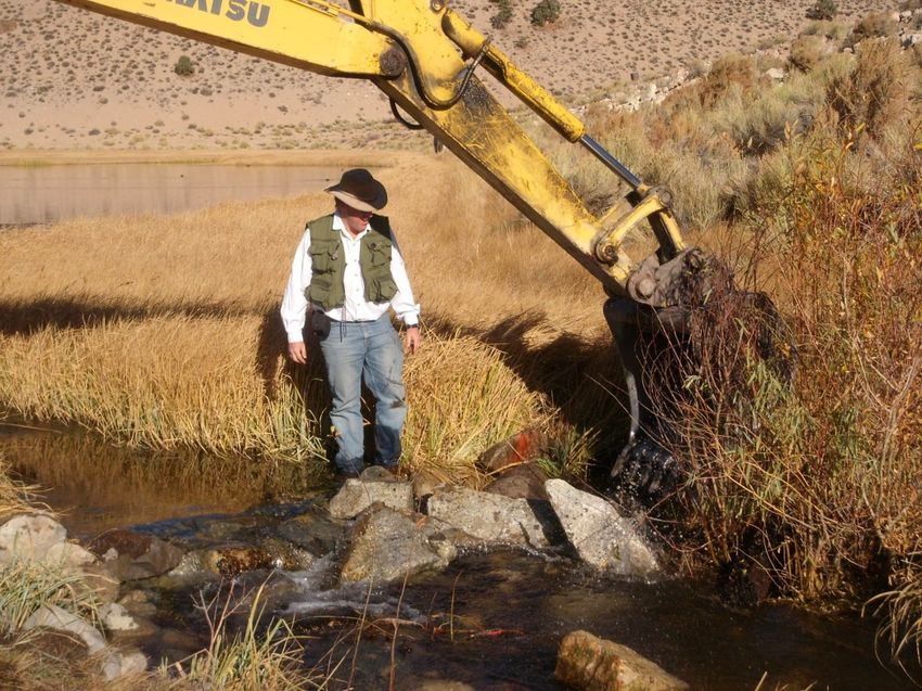
Title 210 – National Engineering Handbook

Issued February 2021

In accordance with Federal civil rights law and U.S. Department of
Agriculture (USDA) civil rights regulations and policies, the USDA, its
Agencies, offices, and employees, and institutions participating in or
administering USDA programs are prohibited from discriminating based
on race, color, national origin, religion, sex, gender identity (including
gender expression), sexual orientation, disability, age, marital status,
family/parental status, income derived from a public assistance program,
political beliefs, or reprisal or retaliation for prior civil rights activity, in
any program or activity conducted or funded by USDA (not all bases
apply to all programs). Remedies and complaint filing deadlines vary by
program or incident.

Persons with disabilities who require alternative means of
communication for program information (e.g., Braille, large print,
audiotape, American Sign Language, etc.) should contact the responsible
Agency or USDA's TARGET Center at (202) 720-2600 (voice and TTY)
or contact USDA through the Federal Relay Service at (800) 877-8339.
Additionally, program information may be made available in languages
other than English.

To file a program discrimination complaint, complete the USDA
Program Discrimination Complaint Form, AD-3027, found online at
How to File a Program Discrimination Complaint and at any USDA
office or write a letter addressed to USDA and provide in the letter all of
the information requested in the form. To request a copy of the complaint
form, call (866) 632-9992. Submit your completed form or letter to
USDA by: (1) mail: U.S. Department of Agriculture, Office of the
Assistant Secretary for Civil Rights, 1400 Independence Avenue, SW,
Washington, D.C. 20250-9410; (2) fax: (202) 690-7442; or (3) email:
program.intake@usda.gov.

USDA is an equal opportunity provider, employer, and lender.

        (210-650-10, 2020 Ed., Feb 2021)
                                                                        650.10-i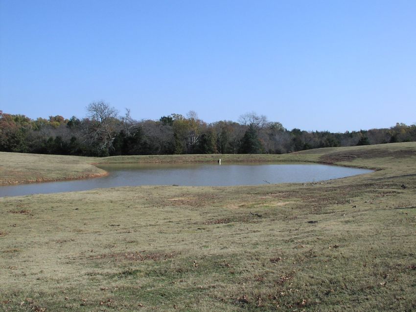
Title 210 – National Engineering Handbook

                                              Chapter 10             Gully Treatment

                                                  Table of Contents
650.1000 Introduction .............................................................................................................. 10.1
     (A) Purpose and Scope....................................................................................................... 10.1
     (B) Definition..................................................................................................................... 10.1
     (C) Impacts of Gullies ........................................................................................................ 10.2
     (D) Causes of Gullies ......................................................................................................... 10.3
650.1001 Planning .................................................................................................................... 10.4
     (A) Process Overview ........................................................................................................ 10.4
     (B) General Planning Considerations ................................................................................. 10.4
     (C) Channel Evolution Model ............................................................................................ 10.5
650.1002 Gully Treatments ...................................................................................................... 10.8
     (A) Overview ..................................................................................................................... 10.8
     (B) Gully Treatment by Vegetative Means ........................................................................ 10.8
     (C) Gully Treatment by Filling and Shaping .................................................................... 10.10
     (D) Gully Treatment by Water Diversion or Retention .................................................... 10.11
           (i) Water Diversion .................................................................................................... 10.11
           (ii) Water Retention ................................................................................................... 10.12
     (E) Gully Treatment by Grade Stabilization Structures.................................................... 10.13
           (i) Structural Measures .............................................................................................. 10.14
           (ii) Earthfill Structures with Vegetated Spillway Only: ............................................. 10.16
           (iii) Gully Plugs ......................................................................................................... 10.16
           (iv) Gully Farming..................................................................................................... 10.16
     (F) Gully Treatment and Sediment Control with Water and Sediment Control Basins .... 10.16
     (G) Gully Treatment by Structures for Water Control...................................................... 10.17
650.1003 Surveys ................................................................................................................... 10.19
650.1004 Design Guidelines................................................................................................... 10.19
650.1005 Installation of Measures .......................................................................................... 10.21
650.1006 Maintenance ........................................................................................................... 10.22
650.1007 References .............................................................................................................. 10.23
650.1008 Acknowledgments .................................................................................................. 10.24

                                             (210-650-10, 2020 Ed., Feb 2021)
                                                                                                                               650.10-ii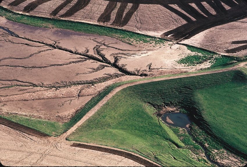
Title 210 – National Engineering Handbook

                                                       Table of Figures
Figure 10-1: Typical gully formation showing steep sides and upslope expansion ................. 10.1
Figure 10-2: Gullies can rapidly expand and adversely impact farmland ................................ 10.2
Figure 10-3: Floodwater storage in this watershed dam has been severely impacted by
  sedimentation ......................................................................................................................... 10.3
Figure 10-4: The Channel Evolution Model (from Figure 3-4a 210-NEH-654-3) ................... 10.6
Figure 10-5: A vegetated swale - CEM Type I without channel .............................................. 10.6
Figure 10-6: Newly formed gully advancing into a HGM Slope wetland ............................... 10.8
Figure 10-7: Gully site stabilized with shaping and vegetation ............................................... 10.9
Figure 10-8: Gully site stabilized with filling, shaping and planting to a grass waterway ..... 10.11
Figure 10-9: Gully forming by emptying terraces into an unprotected outlet ........................ 10.12
Figure 10-10: Terrace system protecting field from gully formation ..................................... 10.13
Figure 10-11: Concrete drop structures at outlet of grassed waterways ................................. 10.14
Figure 10-12: Gullies treated with aluminum drop structure, shaping, and critical area planting
  ............................................................................................................................................. 10.15
Figure 10-13: Gully treated with a pond structure ................................................................. 10.15
Figure 10-14: Gullies treated with low structures and gully farming..................................... 10.16
Figure 10-15: Critical water flow profile ............................................................................... 10.17
Figure 10-16: Layout of Structures........................................................................................ 10.18
Figure 10-17: Stone water control structures used for stabilization of a slope wetland ......... 10.18

                                                (210-650-10, 2020 Ed., Feb 2021)
                                                                                                                                      650.10-iii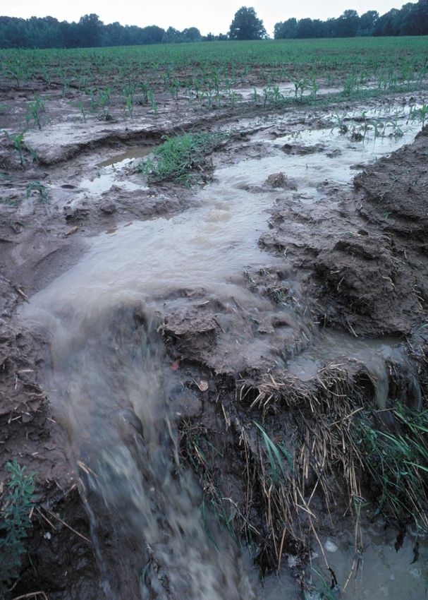
Title 210 – National Engineering Handbook

                   Part 650 – Engineering Field Handbook
                           Chapter 10 – Gully Treatment

650.1000 Introduction

  (A) Purpose and Scope
     (1) Chapter 10 provides conservation professionals with a guide for the stabilization of
         active gullies by vegetative, structural measures or a combination thereof. The focus
         of this chapter is on gullies formed by precipitation runoff and seeps.
     (2) This chapter is national in scope and will often be supplemented with regional and
         local information. Additional background on specific designs and sample calculations
         are available in other sources such as Title 210, National Engineering Handbook, Part
         654, “Stream Restoration Design Guide” (210-NEH-654)– Technical Supplement
         14P, “Gullies and Their Control”.
  (B) Definition
     (1) One of the most severe erosion forms addressed by the Natural Resources
         Conservation Service (NRCS) measures are gullies. Gullies are entrenched channels
         extending into areas with previously undefined or weakly defined channels. Gullies
         can be thought of as extensions of a watershed drainage system up into the landscape.
     (2) If unchecked, gullies can erode and deliver sediment through a variety of processes
         that cause loss in soil productivity, channel entrenchment and headward expansion
         into the landscape. Under extreme conditions, gullies can expand into hillslopes
         extending up to the topographic watershed divide. Active gullies are recognized by
         headcuts (primary nickpoints), where there is an abrupt drop in elevation. A
         photograph of a gully impacting a steep field is shown in Figure 10-1.

         Figure 10-1: Typical gully formation showing steep sides and upslope expansion

                              (210-650-H, 2nd Ed., Feb 2021)
                                                                                          650-10.1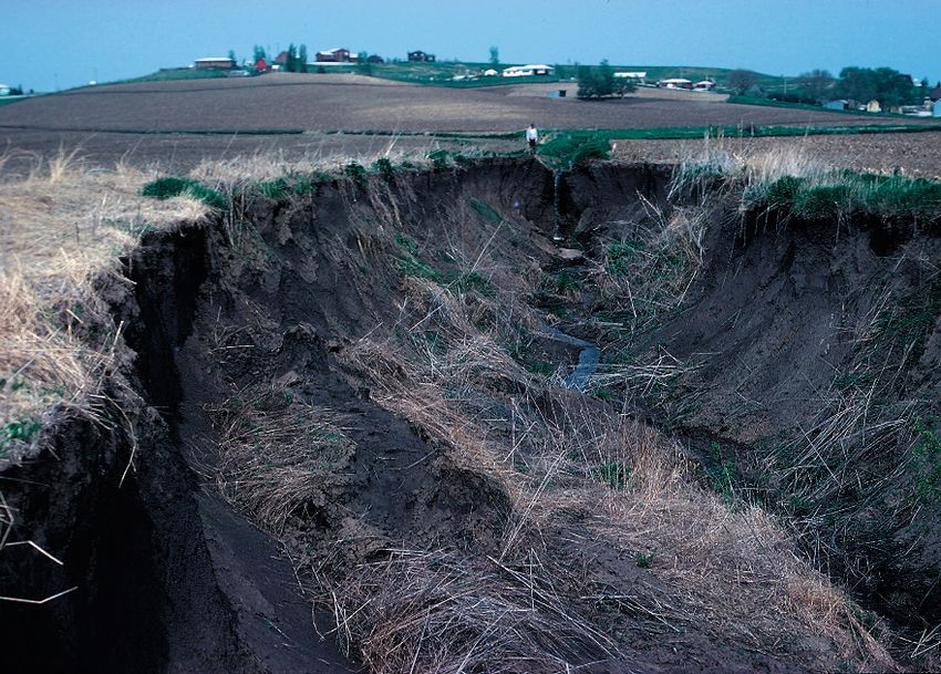
Title 210 – National Engineering Handbook

(C) Impacts of Gullies
   (1) Gullies are significant erosion forms that adversely impact the economy by reducing
       agricultural productivity, lowering the value of farmland, and increasing the cost of
       constructing and maintaining rural infrastructure.
   (2) Gullies directly reduce productivity by making areas of land unfarmable (Figure 10-
       2). Gullies are part of the system where fertile topsoil is transported off the sloped
       areas of fields lowering yields. The degradation of farmland interferes with farm
       operations, undermine farm improvements, endangers livestock, covers bottom lands
       with deposits of soil, and mars the natural beauty of the landscape.

       Figure 10-2: Gullies can rapidly expand and adversely impact farmland

   (3) Gullies can lower the local groundwater table, which reduces water storage in
       headwater stream reaches. The reduction in groundwater can decrease baseflow in
       downstream reaches.
   (4) Gullies increase the cost of public infrastructure when they encroach on highways
       and roads, force the lengthening of bridges, and increase sediment deposition that
       fills road ditches, plugs road culverts and reduces the capacity of drainage channels.
   (5) Gullies can extend into wetland areas, adversely altering wetland hydrology and even
       serving to drain them. The impact of gullies is particularly pronounced on wetlands
       that meet the definition of Slope wetlands in the hydrogeomorphic (HGM)
       classification system where groundwater inflows support wetland hydrology. Further
       discussion on wetland impacts and the definition of wetland types is found in 210-
       NEH-650, Chapter 19, “Hydrology Tools for Wetland Identification and Analysis”
       (210-NEH-650-19)

                            (210-650-H, 2nd Ed., Feb 2021)
                                                                                    650-10.2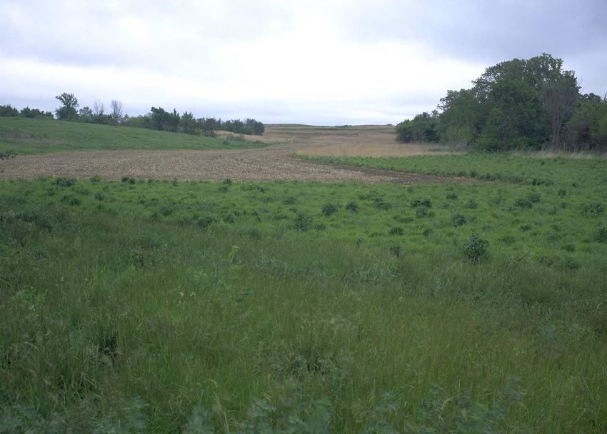
Title 210 – National Engineering Handbook

   (6) The adverse effects of gullies can extend throughout the watershed. Sediment
       sourced from gully erosion can adversely impact water quality, fill channels, increase
       flooding, and kill native vegetation. Sediments from gully erosion can ultimately fill
       reservoirs, shortening their effective life. A reservoir that has been severely impacted
       with excessive sedimentation from its watershed is shown in Figure 10-3.

       Figure 10-3: Floodwater storage in this watershed dam has been severely impacted by
       sedimentation

   (7) Gullies can vary in scale and impact. Some gullies can heal through natural
       vegetative succession over time while many are more permanent and will get larger.
       Still other gullies are ephemeral and can be plowed over, only to reappear during wet
       seasons.
(D) Causes of Gullies
   (1) It is important that conservation professionals be acquainted with the practices and
       conditions that cause gullies. This knowledge is necessary to assist the landowner in
       selecting farming practices, land use changes, structures or even cultural measures
       which will prevent further erosion and help to control existing gullies.
   (2) Gullies are caused by runoff water that concentrates in surface depressions and
       drainageways, flowing at a velocity sufficient to detach and carry away soil particles.
       The power to erode increases as the stream increases in size, velocity, and duration.
       The severity of gully development depends on several factors including soil type,
       vegetation, rainfall, concentration of flow, the presence of springs, and human
       disturbances.
   (3) Gullies on HGM Slope class wetland landscapes will have groundwater discharging
       from the banks and will have continuous baseflow. Groundwater discharge through
       the banks usually contributes to unstable slopes.

                             (210-650-H, 2nd Ed., Feb 2021)
                                                                                       650-10.3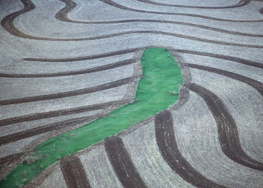
Title 210 – National Engineering Handbook

     (4) If the depression or drainageway is not protected from erosion, a gully will form and
         be enlarged by subsequent flows until the gully system reaches equilibrium. Many
         large gullies have formed because simple steps were not taken to stop them in their
         early stages.
     (5) Drainageways which collect runoff water that may form gullies may be natural or
         may have been caused by:
              • Improperly located farm roads, field and access roads, and trails.
              • Livestock trails.
              • Up-and-down slope cultivation.
              • Unprotected terrace outlets and unvegetated waterways.
              • Unrepaired breaks in terraces and diversions.
              • Improperly designed drainage or diversion channels without needed
                  vegetative or structural protection.
              • Lack of vegetation and rilling on bare slopes.
              • Rainfall that exceeds the capacity of drainage or conservation structures.
              • Improperly designed and/or placed road drainage structures.
              • Built-up fence rows or property boundaries.
              • Grass waterways that need sediment removal.
              • Improper land use
              • Soluble salts or other adverse runoff water components that destroy
                  vegetation.
     (6) It is important for conservation professionals to apply appropriate assessment tools in
         the correct context. For example, the assessment of fluvial concepts is useful in many
         situations but are not applicable in all cases. There are reaches where the landscape
         does not feature a defined floodplain associated with a stream channel. A channel
         may have existed prior to gully formation, but the stable channel capacity often
         cannot be defined in terms of geomorphological principles such as “bankfull
         discharge,” or “channel forming discharge.” In many cases, the pre-gully landscape
         did not feature a channel at all.

650.1001 Planning

  (A) Process Overview
     (1) Gully treatments should be planned according to the NRCS Nine Step Conservation
         Planning Process, described in the National Planning Process Handbook (NPPH).
     (2) In the initial planning phase, it is critical that a planner collect and analyze data about
         a gully erosion site. By identifying existing resource concerns and opportunities for
         improvement the planner facilitates communication with a client so that their
         objectives may also be properly identified. Clear objectives and an accurate
         assessment of existing conditions defines the scope of the project and allows a
         designer to more easily formulate and choose between design alternatives
  (B) General Planning Considerations
     (1) Gully control can best be attained through a plan that considers the cause of the
         gulling including the history of the site, what may have caused the gully to form, the
         watershed conditions, as well as treatment of the gully itself.

                               (210-650-H, 2nd Ed., Feb 2021)
                                                                                           650-10.4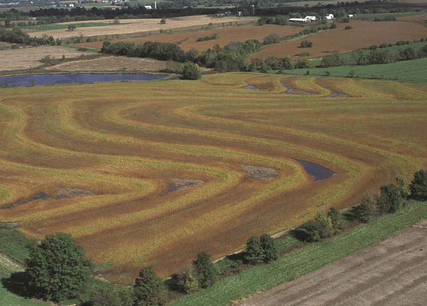
Title 210 – National Engineering Handbook

   (2) Gullies occur on a variety of landscapes and land covers. A conservation plan for, or
       the conservation treatment of, any piece of land should consider all needed and
       feasible gully stabilization work. It is important to determine the planning objectives
       before selecting treatment alternatives. Some gullies can be addressed by simply
       changing grazing or farming practices that reduce the stress while many require
       direct intervention and a comprehensive plan. The plan may include treatments and
       practices such as critical area plantings, grassed waterways or outlets, grade
       stabilization structures, structures for water control, diversions, filter strips, riparian
       forest buffers, ponds, and water and sediment control basins. The plan should
       consider conservation practices that can work singly, or as systems, to accomplish the
       following:
       (i) Interception of runoff water above the gullied area with a diversion or terraces
            that provides for a stable outlet of the runoff.
       (ii) Retention of runoff water on the drainage area by tillage practices, vegetation
            and structures.
       (iii) Drainage of seep water
       (iv) Elimination of the gully by filling and shaping the drainageway to a stable outlet
            with earth moving equipment for critical area planting or grassed waterway
            development.
       (v) Revegetation, either by natural processes or by critical area planting and grassed
            waterway development to a stable outlet.
       (vi) Changing farming practices
       (vii) Construction of grade stabilization structures to control the grade of the gully
            and detain or impound water.
       (viii) Installation of modified subsurface (underground) outlets at tile drain outfalls
            to restore groundwater.
       (ix) Installation of structures for water control (structural and/or plant based) in
            series to raise the water surface profile of surface and groundwater, to induce
            channel aggradation and promote the growth of hydrophytic and phreatophytic
            vegetation.
       (x) Complete exclusion of livestock.
       (xi) Control of sediment from active gullies with Water and Sediment Control
            Basins.
       (xii) Soil Bio-engineering techniques to stabilize wet or unstable banks.
   (3) Problem identification for gully treatment should include an assessment of the cause
       of the erosion as well as how it is expected to proceed. This can be facilitated using a
       variety of evaluation tools including the Channel Evolution Model (CEM) as well as
       an understanding of soils and hydrology at the site.
(C) Channel Evolution Model
   (1) The Channel Evolution Model (CEM) was developed to help predict the changes a
       channel may go through during the process of headcutting. The CEM can be used to
       help determine whether to treat the channel bed, banks, or both. This model is
       expressed as a sequence of Types expressed usually with sections that indexes the
       flow depth (h) occurring during the 2 year storm (Q2) relative to the critical bank
       height (hc) where the banks become geotechnically unstable. The CEM is illustrated
       in Figure 10-4.

                             (210-650-H, 2nd Ed., Feb 2021)
                                                                                        650-10.5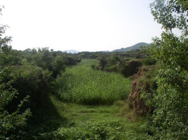
Title 210 – National Engineering Handbook

    Figure 10-4: The Channel Evolution Model (from Figure 3-4a 210-NEH-654-3)

(2) The Type I class in the CEM represents a stable channel or water course. In a field,
    this may also be a swale or a broad, saturated and vegetated slough (Figure 10-5).
    This may be classified as an HGM Slope type wetland.

Figure 10-5: A vegetated swale - CEM Type I without channel

                         (210-650-H, 2nd Ed., Feb 2021)
                                                                                 650-10.6
Title 210 – National Engineering Handbook
(3) Erosive storm events or a reduction in ground cover/channel resistance can cause the
waterway to transition into a Type II and begin to down cut. Increased channel
conveyance due to downcutting, ditch cleanout, or channel bank erosion below a site
can also cause a transition to Type II. As this transition starts, a channel is formed or,
if a stable channel had existed, it deepens. At this point, both channel bed and bank
stabilization must be incorporated. This may be vegetative, structural or a
combination of both.
(4) As the channel forms and deepens, support to the banks is reduced and the channel
begins to widen. This is a Type III. If the waterway is in this stage, vegetative bank
stabilization alone may be adequate. However, significant grading may also be
required, which disturbs potentially stable land and may make the problem worse.
(5) Left untreated, the gully will begin to form a new equilibrium. Sediment from the
banks and from upstream will deposit and form a new quasi floodplain at a lower
elevation. This is a Type IV and will eventually transition into a Type V. The entire
process can result in significant negative impacts to the adjacent land as well as to
receiving waterways below the gully. In addition, the process may cycle and repeat in
an untreated gully. If the Channel is Type IV or V, a vegetative treatment may be
adequate.
(6) If the gully is very large, it may not be possible to restore the original ground surface.
It is also important to determine if the gully channel bottom is actively incising or
there are nick points advancing into the area of interest, or if the active erosion is
limited to the banks.
(7) If the soil map unit on the site is one that is associated with stream floodplains; the
site is probably a degraded stream channel and may not respond well to gully
treatment techniques. If the soil is hydric, or has attributes associated with
groundwater inflow, it may be a degraded wetland.
(8) The site in Figure 10-6 shows a gully that is advancing into an intact HGM Slope
type wetland. Gullies on HGM Slope landscapes will have groundwater discharging
from the banks and will have continuous baseflow. This waterway is draining
groundwater discharge from the wetland. Groundwater discharge through the banks
usually contributes to unstable slopes. The wetland in the background corresponds to
CEM Type I or possibly an old CEM Type IV. The channel in the foreground is in
Type II and transitioning into Type III. Addressing the gully at this point will be
significantly more economical than allowing it to proceed. However, it would be
important to examine downstream conditions as well.
(9) See 210-NEH-654-3 for more information on the development of CEM and its
application in fluvial systems.
(210-650-H, 2nd Ed., Feb 2021)
650-10.7Title 210 – National Engineering Handbook
Figure 10-6: Newly formed gully advancing into a HGM Slope wetland
650.1002 Gully Treatments
(A) Overview
(1) Gullies can be treated by a variety of techniques ranging from land management,
water retention, vegetation control, and/or by structural measures. Different
approaches may be needed for landowners amid differing situations. Not one
approach is suitable in all situations. In many situations a combination of techniques
must be used to address a gully.
(2) The NRCS has several conservation practice standards which address specific
measures. Detailed techniques for gully treatment in a variety of conditions are also
included in 210-NEH-654 – “Stream Restoration Design Guide” – Technical
Supplement 14P, “Gullies and Their Control”.
(B) Gully Treatment by Vegetative Means
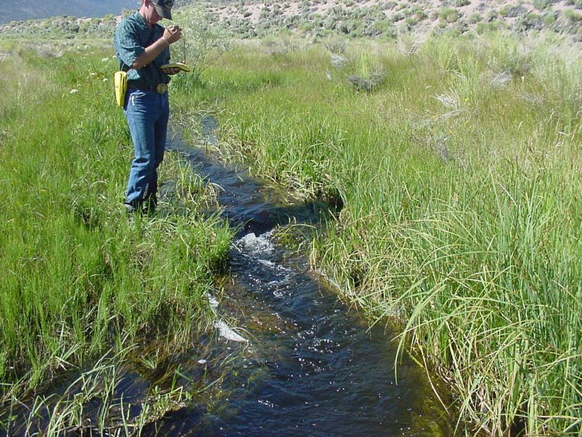
(1) The objective of most gully control work is to stabilize the gully surfaces by
vegetative means. Vegetative techniques are key elements to reversing land uses or
conditions that have artificially left watersheds barren. Vegetation improves soil
cover, promote water absorption, root development, and soil stability. All other
measures should lead to the objective of vegetative stabilization, except in areas
where rainfall is too low to support a good vegetative cover, or a local groundwater
table does not exist to support hydrophytes or phreatophytes.
(2) Many active gully systems, regardless of size or condition, will usually regain a
cover of natural vegetation if it is properly protected and is in an area where
vegetation will readily grow. Diversion or retention of the surface water which
caused the gully, protection from over grazing or heavy use by livestock, protection
from fire, and the removal of other causes of disturbance usually result in growth of
natural vegetation. This vegetation will, in time, cover the gully, promote topsoil
development, and heal the erosion scars (Figure 10-7).
(210-650-H, 2nd Ed., Feb 2021)
650-10.8Title 210 – National Engineering Handbook
Figure 10-7: Gully site stabilized with shaping and vegetation
(3) Nearly all structural measures used, particularly in grassland areas, depend upon
vegetation to support them and to stabilize the soil exposed to excessive runoff.
(4) Of most importance in revegetation is the exclusion of livestock or mechanical
disturbance (vehicle, farm equipment, etc.) from the gullied area.
(5) Many gullied areas or gully banks are not in good condition for vegetative growth
since the fertile topsoil has been washed away, slopes are steep, and the battering of
raindrops on the unprotected soil has produced conditions adverse to plant survival.
Soil tests may be needed to determine if amendments are necessary to reestablish
vegetation. Bank sloping may be necessary before vegetation can be expected to do
an adequate job of gully stabilization. However, it is important to note that bank work
will only be effective if the cause of the downcutting has been fully addressed. Even
after vegetation recovery, gullies remain susceptible to reactivation if conditions
change.
(6) Adapted grasses, trees, shrubs, or vines provide good protection to gullied areas
planned for critical area planting. The desired uses of the area after stabilization helps
to determine the type of vegetation to be established. Treatments that disturb the
ground often need rapid cover and revegetation. Seed mixtures generally include
grasses with quick response. The goal is to provide cover that will help control
erosion, but still allow the desired perennial plants to germinate and grow without
any invasive species getting a chance to establish. The use of sod is an excellent
method of providing cover in disturbed areas where irrigation is available or adequate
rainfall is expected. When available and appropriate to the area of treatment, native
grass, forb, shrub, and tree species should be considered. When rapid cover is
unlikely or added insurance is needed, straw or other mulch is recommended to
protect the topsoil and seed from erosion until the seed germinates and becomes
established. Another option is the use of a manufactured erosion control product such
as erosion control blanket or turf reinforcement mat in combination with seeding.
(7) The restored hydrologic conditions should also be considered when selecting plant
species. The hydrologic condition includes surface flow depth, velocities,
groundwater depth and fluctuations. Landscape Architects and local Plant Materials
Center expertise should be consulted.
(210-650-H, 2nd Ed., Feb 2021)
650-10.9Title 210 – National Engineering Handbook
(8) A stabilized gully may be used for multiple purposes such as a grassed waterway for
terrace outlets, wildlife habitat, woodland area, pasture, or restored headwater
wetland. It should be shaped to the proper size and proportion based on slope,
drainage area and land use. It should not be cultivated, manipulated, or used in a way
that will weaken or destroy the re-established vegetation. The best possible use
should be selected after considering the size of the gully, its location with respect to
other land uses on the farm, the control measures needed, and the type of
maintenance required.
(9) If a gullied drainageway is to be used as a grassed waterway for terrace outlets, the
gully should be shaped to a proper size and proportion to maintain a stable flow
velocity. See 210-NEH-650-7 and 210-NEH-654-8 for more information on stable
velocity calculations. Erosion-resistant grasses or sod should be well established
before any terraces or diversions are constructed to empty into the channel. An
erosion control blanket or turf reinforcement mat can also be used in combination
with vegetative seeding. Trees, vines and shrubs ordinarily are generally not used in
waterways.
(10) If the original conditions supported a headwater wetland, and hydrologic restoration
is the goal, the practices should return the groundwater inflows and groundwater
table as close to prior conditions before gully formation.
(11) Critical area planting of a gullied area in pastureland will be affected by the
intensity of grazing on the area. Limited grazing of a grass vegetation during the
establishment stage is often beneficial in controlling competitive weeds and shrubs.
Overgrazing will seriously hinder establishment. Gullied areas in pastures might be
better managed by permanently protecting these areas from all grazing and retained
for wildlife use after planting with grasses, shrubs, vines or trees suitable for wildlife
habitat. In wooded or gullied areas adjacent to woods, it is desirable to plant trees of
an adapted species and use the area as protected woodland.
(12) In gullied areas where erosion is slow and not having an immediate economic,
safety or environmental impact, the slowest but cheapest method of gully control is
protection from disturbance. Good results may be obtained, and heavy expense
avoided by the simple process of fencing the area to exclude grazing or cultivation.
However, if the gully has progressed to a significant size, protection by itself may not
be sufficient.
(C) Gully Treatment by Filling and Shaping
(1) Elimination of the gully or critically gullied area by filling and shaping may be the
most practical or feasible means of treatment in preparation for critical area planting
or grassed waterway development (Figure 10-8), as long as the downstream end of
the waterway is stabilized first. When this method of treatment is used, the gully or
gullied area is shaped and smoothed so that the area can be established to vegetation
and maintained with regular farm equipment. Where practical, the gully should be
reshaped to provide stable velocities and other desirable hydraulic characteristics. See
210-NEH-650-7, for more information on the design of grassed waterways.
(2) During backfill of gullies, the soil should be compacted since uncompacted material
offers little resistance to erosion. It is best to fill field gullies during the time of year
when a close growing crop may be seeded immediately on the disturbed area to
protect it from erosion. Partial filling or shaping should be discouraged since the
partial blocking of the waterway often causes overfalls and increased gully erosion.
This can result in more land and soil being lost than if the gully were untreated.
(210-650-H, 2nd Ed., Feb 2021)
650-10.10Title 210 – National Engineering Handbook
(3) Reshaped gully slopes on steep slopes (over 25% but can be less for some soil
conditions) can be difficult to stabilize with standard erosion control practices. Soil
from an appropriate borrow area is typically used to fill in and reshape the treatment
area. Adjacent soils may be highly erodible and intensive erosion control measures
may be needed to prevent gully formation in these areas.
Figure 10-8: Gully site stabilized with filling, shaping and planting to a grass waterway
(D) Gully Treatment by Water Diversion or Retention
(1) Reduction of the runoff which flows through a gully is one of the most effective
control measures. This may be accomplished by diverting all or most of the runoff to
a protected outlet or by holding excess rainfall on the land in the drainage area.
Where these methods are feasible, they should be installed before other needed
control measures are attempted within the gully.
(i) Water Diversion
• Water diversions intercept and transmit stormwater away from the gully.
They are appropriate when roads, terraces, parking lots, urban and housing
developments, water transmission or other activities have captured or
diverted flow into the gully channel. Removing other contributing flow
sources can help stabilize active gullies and are used when there is a place to
safely divert the water. However the designer should note that, the larger the
contributing drainage, the less likely this technique will be effective.
• Care should be given to the outlet location of the diverted water to prevent
causing additional problems. The diversion outlet should be on relatively flat
to moderately sloping terrain with good cover and infiltration capability.
Where it is not possible to empty a diversion onto a smooth, well-vegetated
area or into a protected outlet, the water should not be diverted; otherwise,
the diverted runoff may cause gullying in the disposal area (Figure 10-9). It
may be possible to divert water from several gully heads to a common
location and install a single (potentially more economical) stabilizing
structure rather than multiple structures.
• Diversions usually are constructed from the upper side of the diversion ridge
to provide a wide channel section and easier construction. If possible,
diversions constructed adjacent to a gully or at the head of a gully nick point
(210-650-H, 2nd Ed., Feb 2021)
650-10.11Title 210 – National Engineering Handbook
or overfall should be generally located away from the edge of the gully a
distance equal to at least three times the depth of the gully. This will provide
space for the gully banks to slough and stabilize, or to be shaped, without
endangering the diversion. However, this general guidance may need to be
modified for certain soil types.
• Where a small gully has started on an area of sparse vegetation in
pastureland, it is often possible to stop head cutting by constructing an
eyebrow-shaped ridge above the gully head with the ends of the ridge leading
slightly downslope onto good grass cover. This is a temporary measure and
requires considerable skill and care in the selection of outlet areas. Prompt
application of revegetative measures in the gully should follow this practice.
Figure 10-9: Gully forming by emptying terraces into an unprotected outlet
(ii) Water Retention
• Proper land use, management, conservation cropping, and tillage practices
are the first steps in holding water on the drainage area of a gully. These can
be supplemented, as necessary and feasible, by other water-holding measures
to further reduce the runoff into the gully.
• Level impounding terraces provide storage and can be farmed where
cropland is involved in the drainage area of the gully (Figure 10-10) and
works particularly well in in arid and semi-arid climates. The ends may be
left partially open, if necessary, to drain part of the water from the terrace
channel to prevent drowning out of crops or pasture vegetation as long as the
exit area is stabilized to safely handle the overflow. If level terraces are to
retain all the runoff in humid areas, they should be constructed only on
permeable soils and mild slopes. Designers should note that level terraces
can be compromised by overflow during frequent or large storm events. See
210-NEH-650-8 for specifics on terrace design.
• Runoff water often can be prevented from entering or flowing through
relatively large gullies using carefully located earthen dams and graded
terraces. The gully head can be flooded out with a pond which may stop
gully erosion.
(210-650-H, 2nd Ed., Feb 2021)
650-10.12Title 210 – National Engineering Handbook
• Selection of a dam site and the elevation of its spillway is very important.
The dam should be located downstream of the gully head such that the
upstream pool will be high enough, or the long-term upstream channel slope
flat enough to stop the headward (upstream) extension of the gully. The site
should provide enough natural storage so that the auxiliary spillway will not
flow often. Generally, a principal spillway or trickle tube is needed to reduce
frequency and duration of auxiliary spillway flow. In some instances, a good
location for an auxiliary spillway does not exist, so all the design flow will
need to be passed thru the principal spillway.
• In many areas where gullies are formed by runoff from small drainage areas
in arid and semi-arid climates, small earth dams are used to stop headward
cutting and to furnish temporary stock water after periods of rainfall. Such
structures, however, give better protection if equipped with a drop inlet that
will slowly release the impounded runoff water and provide storage space for
runoff from succeeding rains. Since there will be only occasional spillway
discharge, vegetative practices and natural reproduction of native vegetation
below the fill will have an opportunity to control the gully at little cost.
• The two types of earth dam structures described above are often designed as
water and sediment control basins or grade stabilization structures which are
also discussed in the next section.
Figure 10-10: Terrace system protecting field from gully formation
(E) Gully Treatment by Grade Stabilization Structures
(1) It is not always possible to keep runoff water out of gullies by retaining or diverting
the water and the runoff must flow through the gully channel. To do this adequately
may require that both vegetation and structures are planned and established in the
gully at critical times of the year.
(210-650-H, 2nd Ed., Feb 2021)
650-10.13Title 210 – National Engineering Handbook
(2) Planning gully treatment under these conditions may require that the gradient of the
channel be reduced so that water will travel at a nonerosive velocity for the soil type
and vegetative condition. Grade stabilization structures may be required at overfalls,
abrupt changes in gradient, entrances of branch gullies or at other critical points to
supplement vegetation in stabilizing the channel.
(i) Structural Measures
• Structural measures should be used for gully control only when other
measures are not applicable or adequate. Structures are often installed at the
end of grassed waterways to allow runoff to leave the waterway without
causing gully formation.
• The following types of structural measures are used in gully control work.
Photographs are provided in Figures 10-11, 10-12, and 10-13. An outlet
basin or other channel stabilization measures at the downstream end is
generally required for any of these structures. See 210-NEH-650-6,
“Structures” for technical information and design requirements. Figure 6-4 in
210-NEH-650-6 provides a good comparison of the structural measures and
helps with the selection of the most appropriate structure. Guidance is also
available in 210-NEH-654-14, Technical Supplement 14G. Depending on the
amount of elevation drop, multiple structures in series may be needed.
- Straight drop spillway - This type of structure is generally used in the
lower reaches of water diversion systems, such as terraces, diversions,
outlets, and waterways; for large overfalls adjacent to streams; or for
drainage.
- Box inlet drop spillway - This type of structure has the same general usage
as the straight drop spillway but is better adapted to larger flows and sites
where the channel width is limited.
- Hood or canopy inlet spillway - This type of structure uses a straight-pipe
principal spillway in an earth embankment to control head cutting or to
safely drop water to a lower level. This approach is often used where the
topography is sufficient to maintain head on the pipe inlet during design
conditions. This is usually found on a steep slope but can also be found in
confined waterways.
Figure 10-11: Concrete drop structures at outlet of grassed waterways
(210-650-H, 2nd Ed., Feb 2021)
650-10.14Title 210 – National Engineering Handbook
- Drop inlet spillway - This type of structure has the same general usage as
the hood inlet and has the added advantages of permitting drainage of the
pond or fluctuating the water level for management purposes. However, this
type can often handle more flows than a hood inlet. The drop inlet spillway
allows a pipe structure to be used in places where there isn’t enough
topography to implement a hood inlet spillway. The depth of the drop inlet
automatically builds the needed head and the ‘drop’ in a drop inlet absorbs
the energy of the water in the fall.
- Chute spillways - A rock chute, loose riprap, concrete block or formed
concrete structure may be used to safely transfer water to a lower elevation.
Chute spillways are particularly applicable to high flows and where excess
trash and debris may clog a pipe and structure. The chute slope and width
can be adjusted to match the outfall topography. Formless chutes are
limited to areas where temperature variations are moderate, and conditions
are favorable for building the shape of the structure in the soil. The rock
chute or loose riprap structure requires designing and specifying rock size
and gradation. 210-NEH-654, Technical Supplement 14C, “Stone Sizing
Criteria” provides stone sizing techniques.
Figure 10-12: Gullies treated with aluminum drop structure, shaping, and critical area planting
Figure 10-13: Gully treated with a pond structure
(210-650-H, 2nd Ed., Feb 2021)
650-10.15Title 210 – National Engineering Handbook
(ii) Earthfill Structures with Vegetated Spillway Only:
• Earthfill structures with vegetated spillway may be used as grade
stabilization structures and to impound sediment or water for gully treatment,
especially in arid or semi-arid climates. They may also provide temporary
livestock water or be used as Water and Sediment Control Basins. This
system has limited use because a vegetated spillway stable enough to
withstand frequent flows can seldom be found in the right location in gullied
areas, Information on design and installation of earthfill structures with
vegetated spillways can be found in 210-NEH-650-11, “Ponds and
Reservoirs”.
(iii) Gully Plugs
• A gully plug is a small earthen dam constructed at one or more locations
along the gully. Branch packing and wattle check dams can also be used as
gully plugs for small gullies. Information on these and other soil
bioengineering applications of gully plugs is provided in 210-NEH-654-14,
Technical Supplement 14I. Regardless of the size, the gully plug provides
grade control and retains sediment. A key factor in gully plug success is
growth of the vegetation.
(iv) Gully Farming
• Gullies can also be stabilized with low earth or rock structures with
vegetation in the areas between the structures. This approach stops the gully
development in a CEM Type III condition and is illustrated in Figure 10-14.
In arid and semi-arid areas, the flows collected at the gully can add to soil
moisture and collected soils can increase soil fertility. This approach has
been used to facilitate agricultural activities for low resource farming in the
developing world.
Figure 10-14: Gullies treated with low structures and gully farming
(F) Gully Treatment and Sediment Control with Water and Sediment Control Basins
(1) Water and Sediment Control Basins are used where physical conditions or
landownership prevent the treatment of the sediment source by the installation of
gully control measures.
(210-650-H, 2nd Ed., Feb 2021)
650-10.16Title 210 – National Engineering Handbook
(2) This type of structure is a dam, usually equipped with a pipe principal spillway,
constructed across a waterway or at some other suitable location to form a sediment
storage basin. A debris basin is used to preserve the capacity of reservoirs, ditches,
canals, diversions, waterways or streams and to prevent undesirable deposition on
bottomlands. This is done by storing a high percentage of the sediment and other
debris moving out of the drainage area.
(3) The capacity of a debris basin is governed by the volume of sediment expected to be
trapped at the site during the planned useful life of the structure or the improvements
it is designed to protect. Where it is assured that periodic removal of debris will take
place, the design capacity may be reduced accordingly.
(4) Usually the design, layout and construction principles for Water and Sediment
Control Basins are identical to those for principal spillway-type grade stabilization
structures or tile outlet terraces. Only the primary purpose of the structure may differ.
Therefore, previous discussions in this chapter or in 210-NEH-650-8 and 210-NEH-
650-11 of this handbook will apply, depending upon the type of debris basin being
considered.
(G) Gully Treatment by Structures for Water Control
(1) Structures for water control can be used to induce channel deposition and to raise
both the surface and groundwater profile. They usually must be installed in series so
that each structure provides tailwater protection to the upstream structure. They must
also be installed with a spacing and height that creates minimal water surface profile
drop across the structures when flow is at the top of the gully bank. This approach
reduces the potential of a failure due to flanking when out of bank flows return to the
gully downstream of the structure. A bank key is still important to reduce the
potential for piping around the structure but erosion around the structures from return
water is reduced by designing the structures to have a minimal drop during out of
gully flows.
(2) The critical condition for stability is the flow range between incipient out-of-bank
flow and complete backwater conditions (Figure 10-15). Lower flows are within
bank, and higher flows have minimal water surface profile drop.
Figure 10-15: Critical water flow profile
(210-650-H, 2nd Ed., Feb 2021)
650-10.17Title 210 – National Engineering Handbook
(3) Ideally, structures should be placed downstream of points of concentrated flow
reentry, and upstream of points where concentrated flow leaves the watercourse
channel. If a stable reach does not exist downstream of the last structure, a Grade
Stabilization structure may be needed. This could be a separate structure, or the last
structure could be designed to serve two purposes. These structures are often installed
in conjunction with soil bio-engineering techniques which work to reduce flow
velocities, further induce deposition and channel aggradation, decrease the gully
cross-section, and stabilize the banks. Figure 10-16 shows a schematic layout which
accounts for concentrated flow points, the placement below a head cut, and the
placement of the last downstream structure.
Figure 10-16: Layout of Structures
(4) This low impact and cost-effective approach have been commonly applied in wetland
and stream restoration projects and is effective for upland watershed restoration.
Figure 10-17 shows the use of rock structures for stabilization and the establishment
of a Slope HGM class wetland. If a systematic approach is applied, their use can
result in raising the groundwater table, increasing the frequency and extent of surface
inundation, increasing upland sediment deposition, and stabilizing advancing
headcuts.
(5) This concept is very similar to the stream bed stabilization technique called “rock
riffles” or “loose rock structures.” This stream restoration technique is used to
reconnect a degraded channel to the floodplain. Further design guidance is available
in 210-NEH-654-14 Technical Supplement 14G.
Figure 10-17: Stone water control structures used for stabilization of a slope wetland
(210-650-H, 2nd Ed., Feb 2021)
650-10.18Title 210 – National Engineering Handbook
650.1003 Surveys
A. Preliminary surveys should be adequate to determine the gradient and cross sections of
gullies to be treated with vegetation alone or in combination with filling and shaping. In some
cases, hand level data may be satisfactory.
B. A thorough field survey of site locations should be made for any structure measure so that
the most economical type of structure can be designed. Profile and cross-section surveys are
needed to show the characteristics of the watercourse above and below the planned structure
location. The profile should go far enough downstream to reach a stable outlet. The presence
or absence of a stable outlet will determine the selection of the appropriate measure. The
structure may affect the flow of water for quite a distance above and below its proposed site
or influence other structures. Topographic and soils information as well as a geologic
investigation if often needed on the structure site for detailed design. Decisions on these
surveys should be made in the field based on the type of structure being considered.
C. Earth fill structures with drop spillways or chutes may need additional field surveys when
an auxiliary spillway is included. Profile and cross-section surveys of the proposed spillway
sites may be needed for a design that provides adequate capacities at nonerosive velocities.
D. Field surveys should also record the location, pertinent elevations, and sizes of any
bridges, culverts, fence lines, buildings, etc., which might influence the design of the
structure. Determinations must be made as to the size and shape of the watershed and all
other factors that influence runoff and the design of the structure. Additional guidance is
available in 210-NEH-650-1.
E. As previously discussed in this chapter, the designer should consider soil testing to
determine if/what amendments are necessary to establish vegetation.
650.1004 Design Guidelines
A. Guidance for the design of gully treatment measures will be found in 210-NEH-650-6,
“Structures”, 210-NEH-650-7, “Waterways”, 210-NEH-650-8, “Terraces”, 210-NEH-650-9,
“Diversions”, and 210-NEH-650-11, “Ponds and Reservoirs”. Detailed techniques for gully
treatment are also available in in 210-NEH-654-14, Technical Supplements 14G, 14I and
14P. 210-NEH-654, Technical Supplement 14C, “Stone Sizing Criteria” provides stone sizing
techniques.
B. A permanent grade stabilization structure generally must have a stable downstream grade
with minimal degrading after the protective measures are established. If a stable grade is not
available within a reasonable distance of the site, the potential loss of grade should be
estimated and compensated for in the structure design by lowering the apron floor, adding
launchable material, and/or adding other structures in the channel below. Where there is
significant grade control required at the structure location, a pipe structure may be more
suitable than an overfall structure, if topography or storage permits. Stable grade analysis is
addressed in detail in 210-NEH-654-8. Permanent grade stabilization design in fluvial
environment sis addressed in 210-NEH-654-14, Technical Supplement 14G.
C. The type of structure and the site selection will be influenced to some extent by the
availability of materials. For example, if a drop inlet structure is being considered, suitable
core and fill material should be readily available. Available rock suitable for a rubble
masonry structure may be the deciding factor on the type of drop spillway to construct.
(210-650-H, 2nd Ed., Feb 2021)
650-10.19Title 210 – National Engineering Handbook
D. The type of foundation for any proposed site may determine the type and size of structure
to be constructed. Wet, seepy foundations are not suitable for large concrete structures unless
the design includes extensive corrective measures. This may be the place where a drop inlet
structure can work but persistent or excessive seepage must generally be addressed with any
structure. Dry, unstratified foundations are suitable for almost any type of structure. Where
there are wet areas on the structure site, drop spillways or chutes can be constructed in a drier
area and the waterflow diverted to them.
E. When the structure is to control erosion at the gully head or overfall, the site selection
should be carefully made. The crest of any erosion control structure should be set at an
elevation which anticipates the upstream movement of the gully head during the healing
period. It should drown the gully head to prevent further movement.
F. The location for a suitable auxiliary spillway is another important factor in selecting a site
for any erosion control or detention dam where part of the flow is carried through the dam by
a principal spillway. In some cases, drop spillways will need an auxiliary spillway to help
carry the less frequent peak flows around the end of the embankment. Therefore, site
selection and design should include full consideration of this important feature.
G. In the event an auxiliary spillway location is not available, all of the design flow will be
required to be passed thru the principal spillway. If an auxiliary spillway is not needed, it is
good practice to provide a planned overtopping location away from the main structural
measures in the system. This should be where any damage could be more easily repaired.
This provision typically looks like a “low spot” where an auxiliary spillway might normally
be placed, but without any shaped inlet, control section, or exit slope.
H. Scour at the outlet of the principal spillway is one of the important factors leading to
failure of an overfall structure. Scour may be controlled by giving proper consideration in the
design to the:
(1) Stability of the grade below the structure.
(2) Velocities occurring in the downstream channel.
(3) Tailwater elevations for different flow stages.
(4) Dissipation of water energy in the outlet.
I. Scour below drop spillways or chutes usually is reduced as the tailwater elevation is
increased, so placing the floor or outlet apron of the structure at a lower elevation increases
the protection of the structure. Scour at the outlet end of drop inlets is reduced by having the
pipe section extend beyond the toe of the fill with a cantilever outlet, either with or without a
pipe support, or otherwise protecting against undercutting of the pipe. One such method of
protection is the use of a rock (or concrete rubble) outlet basin/plunge pool.
J. The peak and volume of runoff are almost directly proportional to the length and size of
the watershed. The site chosen for a structure may be adapted to a drop spillway, but the
drainage area and runoff may be too large for this type of stabilizing structure. For large
runoff volumes or high peak flows, storage may be required to reduce the peak discharge.
The need for storage should be considered at the time the preliminary site selection is made.
(210-650-H, 2nd Ed., Feb 2021)
650-10.20Title 210 – National Engineering Handbook
K. Consideration should be given to the land use at the proposed site or immediately adjacent
to it. Drop spillways or chutes may be placed in cropland since they do not require permanent
or temporary storage that can damage crops. They also have a very small trap efficiency so
there is minimal crop damage due to sedimentation. Improper land use above, adjacent to, or
below the structure site may seriously reduce the effectiveness of the structure or stability of
the downstream grade. Needed land treatment measures and proper land use should be
applied to the watershed when excessive runoff or siltation would seriously affect the life and
efficiency of the structure.
L. It is important to assess and account for effects of flooding and sedimentation on adjacent
land. Specifically, it is important to assure that it will not cause adverse flooding or
sedimentation either adjacent or upstream of the site. Consideration should be given to design
elements such as freeboard.
M. Sediment load from the drainage area must be considered in the design of structures.
Gullies which produce large amounts of sediment may require an earth dam with a drop-inlet
type debris basin. If selected for use on the site, the earthen dam should be designed with
adequate sediment capacity for the design life of the structure. Open structures can be used to
pass heavy sediment loads when the sediment source cannot be treated and cost or
topography limit opportunities to store sediment behind a structure. However, the
consequences to land and structures downstream of passing sediment must be examined. An
O&M plan is needed which includes measures for periodic cleanout.
N. Extreme size should be avoided. If the drainage area is large enough to require a width of
spillway notch greater than the width of the channel, the cost of construction may be
prohibitive and poor hydraulic conditions at the structure site may result. In such cases, it
may be desirable to consider a box inlet drop spillway or attempt to control only the lateral
gullies entering the main gully.
O. Final selection of the location, type and design of permanent structures, larger than those
normally used in terrace outlet works, should be with the advice and consultation of those
skilled in geology, hydrology, design and construction. 210-NEH-650-2, 210-NEH-650-3,
210-NEH-650-4, and 210-NEH-650-6 contain additional criteria used in design.
650.1005 Installation of Measures
A. 210-NEH-650-1 describes surveys for setting line and grade stakes for construction of the
various structures.
B. Careful clearing and excavation of the site is important since the surfaces between the
structure and the sides and bottom of the gully are points of weakness. All backfill should be
compacted.
C. Structures should be placed so that the discharge from the spillways will not cause
embankment damage or side-cutting or undermining of the downstream banks.
D. Any overfall above an erosion control structure should be sloped to allow water to enter
the pool area without additional erosion, even though the inlet crest may be equal to or higher
than the gully head elevation. Flooding out overfalls is a very effective approach to retarding
the advancement of headcuts.
E. The channel below any structure should be shaped as needed during construction of the
structure. Irregular banks in the outlet channel of an entrenched structural spillway may
erode, affecting the hydraulics at the outlet and depositing sediment that forms to the desired
shape for the outlet channel as well as resulting in undesirable benches downstream.
(210-650-H, 2nd Ed., Feb 2021)
650-10.21You can also read