Claire Juramy, Pierre Antilogus, Andrew Bradshaw, Craig Lage, Stuart Marshall, Andrew Rasmussen, Yousuke Utsumi LPNHE, Paris - SLAC - UC Davis ...
←
→
Page content transcription
If your browser does not render page correctly, please read the page content below
Claire Juramy, Pierre Antilogus, Andrew Bradshaw, Craig Lage,
     Stuart Marshall, Andrew Rasmussen, Yousuke Utsumi
                LPNHE, Paris - SLAC - UC Davis

                  DeMo2021 - 16th June 2021                     1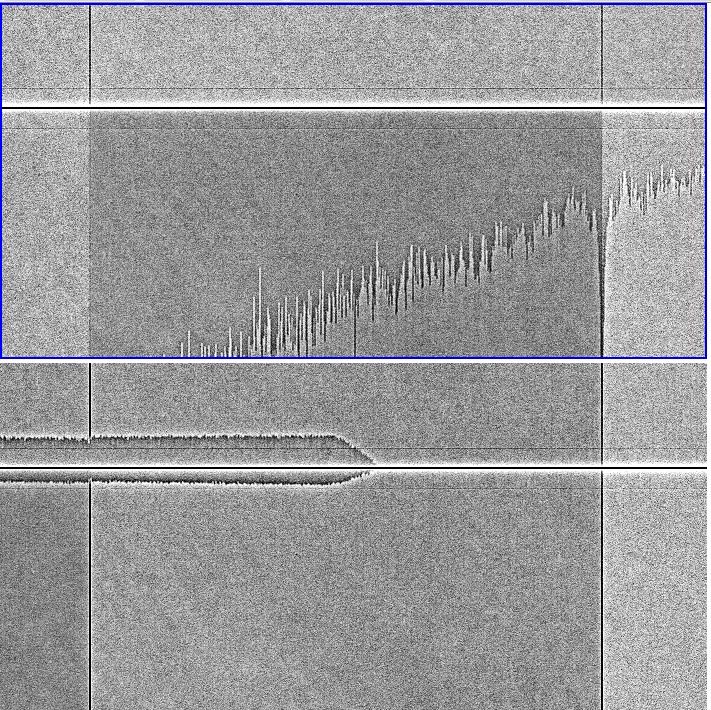
§   LSST focal plane: rafts (9 CCDs): 13x T-e2v CCD250,
    8x ITL STA3800C (+ 4x corner rafts = 3 ITL CCDs)
§   T-e2v CCD250 exhibit variety of «tearing» patterns
    in flat-field images: pollute corrections of Pixel
    Response Non-Uniformity, astrometric distortions
§   First tests with single-sensor test stand:
    understanding generation of tearing patterns,
    mitigation in unipolar mode and in bipolar mode
§   Modelling based on sensor physical analysis
§   Applied to full focal plane, limitations on voltage
    sets

                                                          2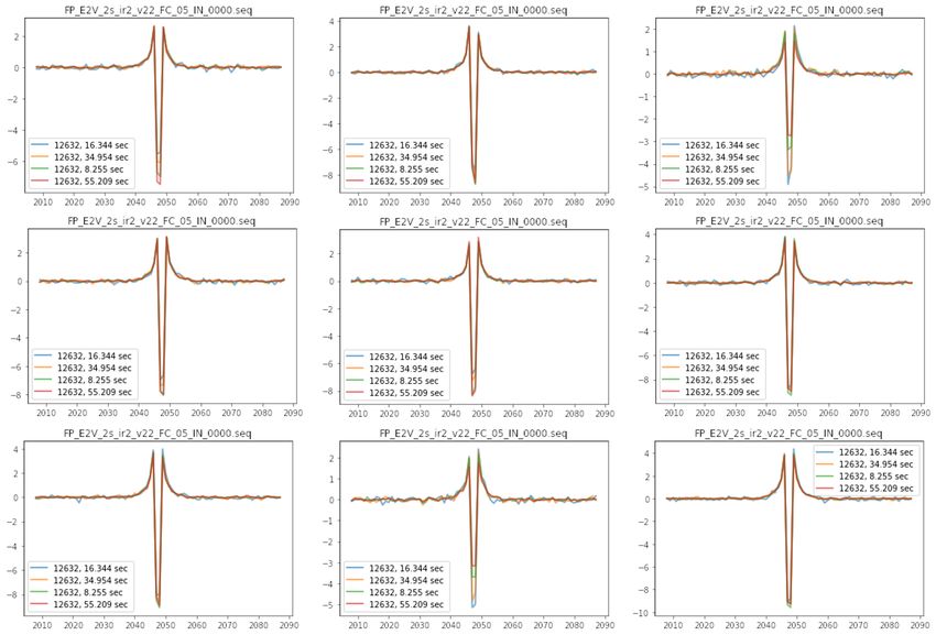
§   T-e2v CCD250 baseline operation: unipolar mode, Back-
    Substrate Bias at -70V
§   16 channels, 16 Mpix, 2s readout
    § Segmentation: ‘corner turn’
    § Blooming stop implant
§   Operating in bipolar mode can have beneficial effects:
    serial CTE, dark current, full well
    § Concerns for sensor safety: BSS to -50V, Parallel Low clock
      voltage PL > - 6V
    § Parallel clock (P4) used as reset switch for second stage of
      output amplifier: ties parallel clock voltages to serial readout
§   Readout electronics:
    § Can drive CCDs with bipolar voltages
    § Cannot shift voltages between exposure and readout (ZTF)
    § Cannot set slopes on clock shifts (voltage-driven)

                                                                         3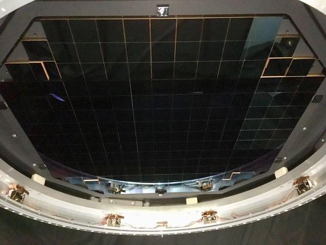
amplitude ~ 7 %

Ø   Effect from channel stops: isolated darker and lighter columns are paired,
    surrounded by excess/deficit respectively
Ø    Same mechanism as brighter-fatter, changing charge carriers and location
                                                                                 4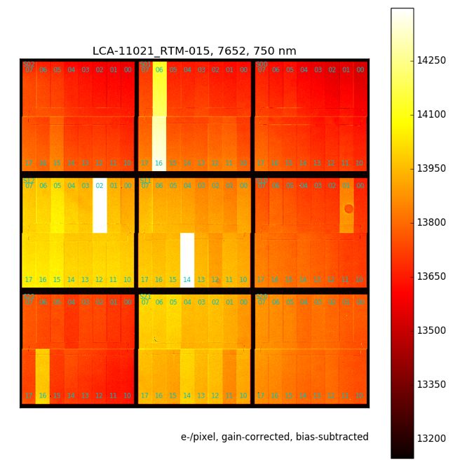
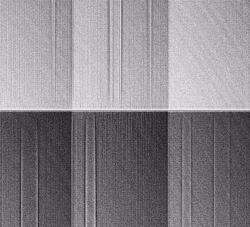
§   Skyline pattern: observed at high deltaP (> 9.5V), builds up from middle of sensor
§   Thin tearing: excess of charges comes before deficit in readout: not an issue with
    parallel transfer

                                                                                         5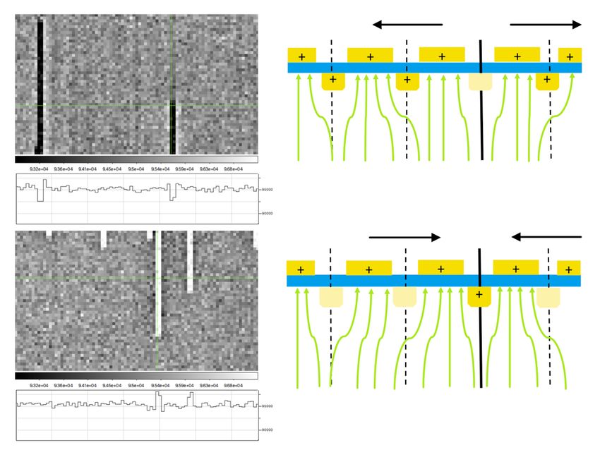
§   Tearing boundaries: better uniformity inside
§   Outside: ‘divisadero’ appears at segment edges
§   Divisadero also appears in frames with no tearing patterns
§   Deficit of holes in the single channel stop between
    segments
         ~ 3% amplitude, symmetrical across segment edges,
         5+ columns wide

                                                                 6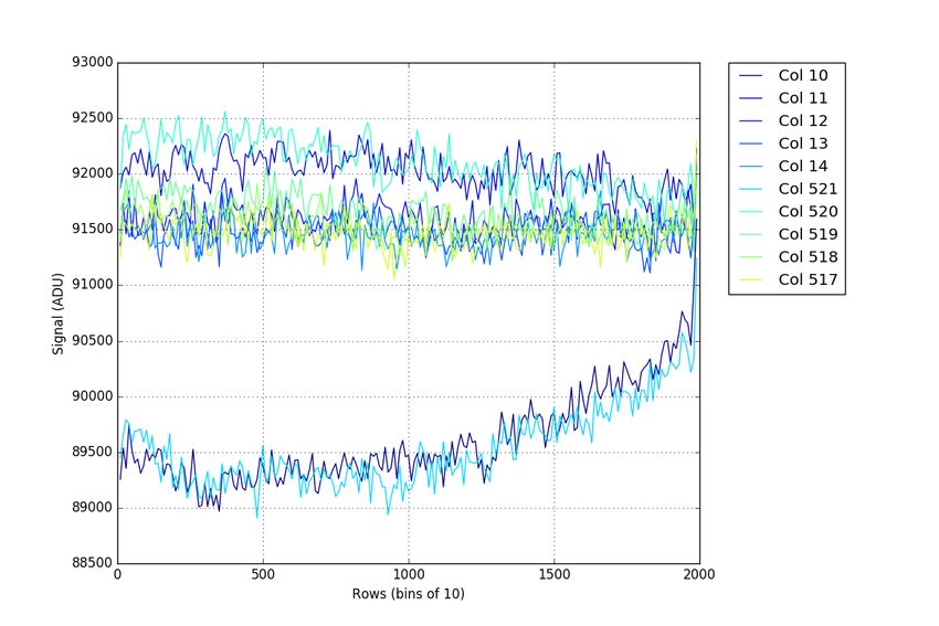
§   Single sensor: operating in bipolar mode with PL < -6.5V
                                   removes the tearing and the divisadero
                               §   Raft (9 sensors): one sensor with a strong bright defect
                                   required an added ‘purge’ step to remove the tearing
                                   pattern.
                                   § All four phases of parallel clocks set to low at the same time
                                   § Right before each exposure
                                   § Similar operations in p-CCDs
                               §   In inversion: holes can circulate
                               §   ‘Purging’ (even with PL = 0V) = smoothing out hole
                                   distributions in channel stops
                               §   Test procedure: start with a ‘purge’ at -7V, then observe
                                   emergence of patterns

purged at 0V   purged at -7V
S1+S2 high                                                                                            7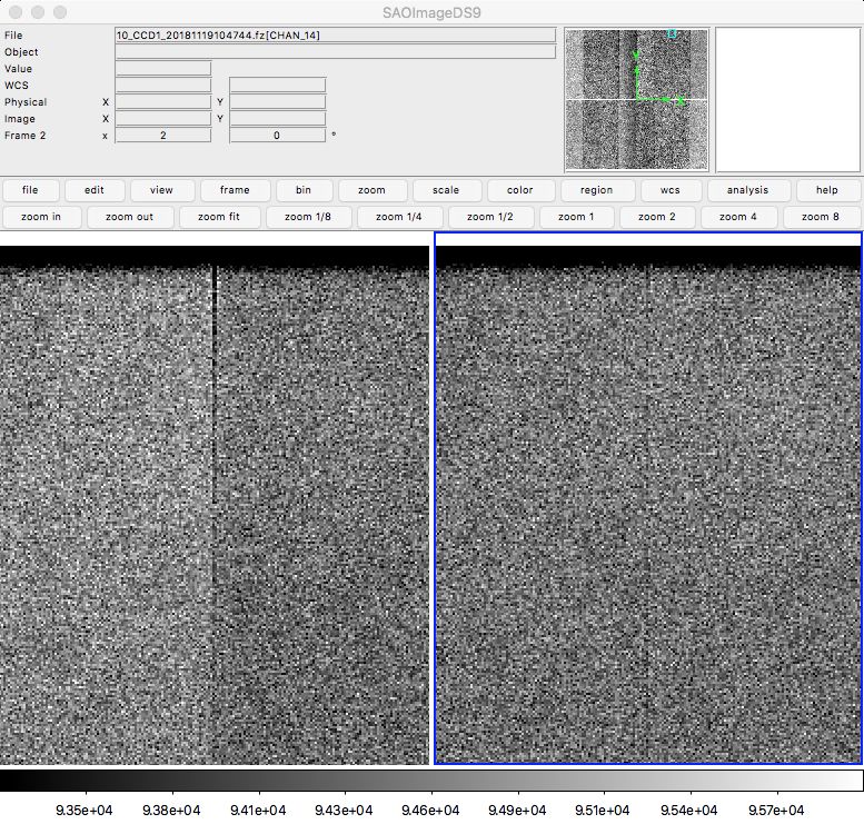
Purge at -7V

    Bipolar read               Unipolar read             Unipolar read (no       Unipolar clear(s)
                               (no clear)                clear), high PU         and read

                                                                         Divisadero
                     No distortions

Read (no/fast clear)          Read (no/fast clear)        Read (no/fast clear)          Unipolar clear(s)
                                                                                        and read

    No distortions                Divisadero         Tearing pattern (large)          Tearing pattern (thin)

§   Distortions in one frame depend on the readout mode in the previous frame, and on
    whether there is a clear, but not on the readout mode of the current frame
§   Incoming photoelectrons are affected by the hole densities fixed before exposure
                                                                                                               8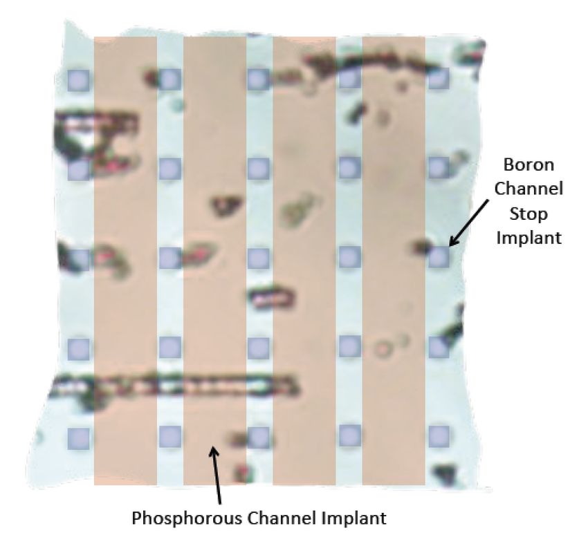
§   Reverse clocking (1,000 rows) in unipolar mode, with high PU value (>9.5 V): reverse
    tearing pattern appears near edges of sensor
§   Pattern matches model that holes have been pushed away from the sensor edges

                                                                                           9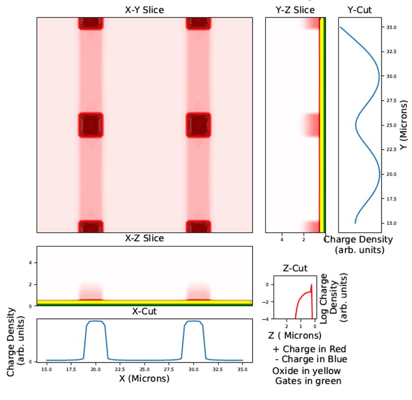
§   “Physical and electrical analysis of LSST sensors”, Lage, C., arXiv:1911.09577
§   Based on SEM micrograph of deprocessed CCD, SIMS analysis
§   Channel stops: ‘dots’ of boron implants (not the case for ITL STA3800C)

                                                           (before applying area factor)   10
§ Model: “Poisson_CCD: A dedicated
simulator for modeling CCDs”, Lage,
C., Bradshaw, A., Tyson, T.,
arXiv:1911.09038
§ Solves Poisson equations numerically
for potential and free carrier densities
§ Simulates photo-electron propagation
§ Can repeat simulation with different
conditions to simulate CCD charge
transport
§ Boron dots act as hole traps
(depending on parallel clock voltages)
11§ Poisson_CCD: compares PL = -6V and PL = -8V: hole density under clock low phases
§ With PU = + 3.5V, 10,000 e-, 190,600 h+
12§ Poisson_CCD: compares PL = -6V and PL = -8V: hole density during ‘purge’ phase
§ With PU = PL, 0 e-, 370,100 h+
13§ Unipolar mode: tearing, or divisadero only (with fast clear)
§ Bipolar mode: variety of structures depending on working conditions and sensor
14§ Path for holes at segment edges, affected
by level of serial clocks
§ Serial clock states during purge
§ Serial flush during exposure
§ Blooming stop
§ Depletion near sensor edges
§ Parallel clock propagation
15§ Fractional displaced signal (per-row): fds = 4*(s-2+s+2-s-1-s+1)/(s-2+s-1+s1+s2)
(from A. Rasmussen, 2014 JINST 9 C04027)
16§ Parallel clock voltages: deltaP = 9.3 V
§ ‘Purge’ duration: 3 ms
§ No serial flush during exposure
§ Longer parallel transfer times (improved full well)
§ Tried other mitigations: reverse flush (issue with bright columns, amplifier boundaries,
reverse tearing)
1718
§   Combination of divisadero and brighter-fatter
§   Shape and amplitude match
                                                    19
§ Early idea: holes generated and removed
by parallel clocking
§ Simpler model: in unipolar mode, there is a
number of holes confined to each channel
stop.
§ After a purge at -7V, when shifting back to
unipolar voltages, the holes come
back/never really left, and are frozen into
the channel stops with a uniform-looking
distribution
§ Parallel clocking for clearing / readout can § In the other channel stops, holes
move the holes in the same direction, with accumulate on the serial register side
efficiency depending on exact parameters until the hole density reaches a limit.
§ In the channel stops at the segment edges, § These two effects cumulate to create
the holes arriving at the serial register can the “divisadero” pattern.
get out.
20§ Transition from “rabbit ears” to tearing
patterns: the clocking moves the holes
efficiently enough along the channel
stops to empty them, starting from the
mid-line.
§ Wide tearing pattern: the edge of the
hole density moves in the readout
direction, until it is blocked by the
accumulated holes, and the tearing
pattern stabilizes.
§ Thin tearing pattern caused by clearing
(and not readout): clearing sequence is
more efficient at moving the holes.
§ Non-uniformity along columns:
§ Clocking in bipolar mode: holes can
difference in total hole content or in move between channel stops, smooths
hole capacity between channel stops.
out distribution
21You can also read