Design and Systems Engineering of AFRL's Demonstration and Science Experiments
←
→
Page content transcription
If your browser does not render page correctly, please read the page content below
Earth Spacecraft and Sensors (ESS)                                                   Paper No. GT-SSEC.D.1

                                      Design and Systems Engineering of
                            AFRL’s Demonstration and Science Experiments

                            Dan Cohen*, Gregory Spanjers, James Winter, Gregory Ginet, Bronislaw Dichter,
                                        Aaron Adler*, Martin Tolliver, and Jason Guarnieri*

                                     US Air Force Research Laboratory, Space Vehicles Directorate
                                             Kirtland AFB, NM and Hanscom AFB, MA

                                                               ABSTRACT
                                The Air Force Research Laboratory (AFRL) Space Vehicles Directorate
                                has developed the Demonstration and Science Experiments (DSX)
                                mission to research technologies needed to significantly advance
                                Department of Defense (DoD) capability to operate spacecraft in the
                                harsh radiation environment of medium-earth orbits (MEO). The ability
                                to operate effectively in the MEO environment significantly increases the
                                DoD’s capability to field space systems that provide persistent global
                                targeting-grade space surveillance, high-speed satellite-based
                                communication, lower-cost GPS navigation, and protection from space
                                weather on a responsive satellite platform. The three DSX experiments
                                areas are:
                                1. Wave Particle Interaction Experiment (WPIx): Researching the
                                   physics of very-low-frequency (VLF) transmissions in the
                                   magnetosphere and characterizing the feasibility of natural and man-
                                   made VLF waves to reduce space radiation;
                                2. Space Weather Experiment (SWx): Characterizing and modeling the
                                   space radiation environment in MEO, an orbital regime attractive for
                                   future DoD and commercial missions;
                                3. Space Environmental Effects (SFx): Researching and characterizing
                                   the space weather effects on spacecraft electronics and materials.
                                DSX uses a modular design that allows for launch either as a primary
                                satellite on a conventional launcher, such as a Minotaur, or as a
                                secondary payload on a larger rocket, such as the Evolved Expendable
                                Launch Vehicle (EELV).
                                An overview of the DSX spacecraft design, requirements, systems
                                engineering approach, bus subsystems, payload designs, and experiments
                                will be described.

             *Contractors

Cleared for public release by US/PA per VS05-0648 on 3NOV05
U.S. Government work not protected by U.S. copyright.         Page 1 of 17 Pages         GATech Space Systems Engineering Conference
                                                                                                                November 8-10, 2005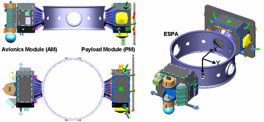
Earth Spacecraft and Sensors (ESS) Paper No. GT-SSEC.D.1
1.0 Introduction
The Demonstration and Science Experiments (DSX), is AFRL’s fourth space science technology
experiment. It was originally conceived by AFRL researchers in 2003 to conduct physics based
experiments, and was selected as an AFRL mission in 2004. With primary funding from AFRL, DSX
enjoys additional support from DARPA and NASA, and is comprised of elements provided by AFRL,
NASA, academia, and many contractors.
The DSX spaceflight experiment comprises three major research areas, which together will pave the way
for new DoD capabilities in space surveillance, microsatellites with significant operational capabilities,
and protection of space assets from natural and enhanced radiation environments. This mission will
advance the warfighter’s capabilities in communication, surveillance, and navigation. The DSX
experiments include research in three major experiment categories.
The physics of Very Low Frequency (VLF, 3-50 kHz) electromagnetic wave injection from space and
ground-based transmitters, propagation, and wave-particle interactions in the magnetosphere comprises
the first category, Wave Particle Interaction Experiments (WPIx). Equipment on DSX will transmit and
receive VLF waves and quantify their effect on the trapped electron populations in the magnetosphere.
Detailed measurement and mapping of high and low energy particle and plasma distributions; radiation
dose rates, local magnetic fields and pitch angle distributions in the poorly characterized MEO
environment and slot region make up the DSX Space Weather Experiments (SWx). The third major
experiment category, Space Environmental Effects (SFx), involves characterization of the effects of space
weather and the space environment on materials and electronics. SFx consists of NASA’s Space
Environment Testbed, as well as AFRL developed photometers and radiometers.
Coupling these experiments into a single platform provides a lower-cost opportunity for AFRL due to
their common requirements and goals. All three experiments need a 3-axis stabilized spacecraft bus, a
suite of radiation sensors, and extended duration in a MEO orbit.
2.0 Flight Experiment Concept
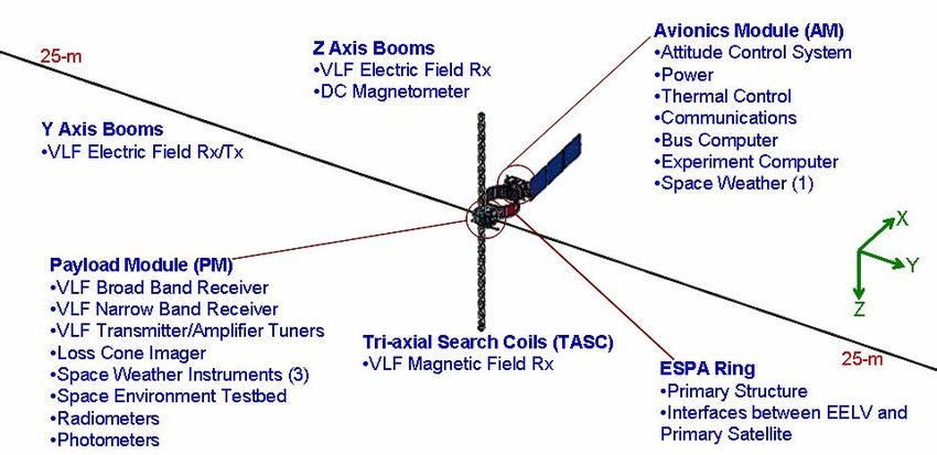
The functional baseline configuration for the DSX flight experiment is shown in Figure 1. The core is the
Evolved Expanded Launch Vehicle (EELV) Secondary Payload Adapter (ESPA) Ring [1,2], which is
used to maximize launch opportunities on both Space Test Program (STP) and operational DoD
launchers. ESPA was developed and designed by CSA Engineering. Every EELV launch is a potential
ride for an ESPA ring, and thus also for DSX. The ESPA ring comprises the primary structure for DSX,
and is upgraded to provide host spacecraft functions (avionics, TT&C, ADCS, C&DH, and power
management and distribution) by the addition of components packaged on an avionics module (AM). The
DSX payloads (including deployable booms) are mounted on an identical structure, the payload module
(PM), attached to the ESPA ring opposite the avionics module. The AM and PM together comprise the
DSX Host Spacecraft Bus (HSB). The entire assembly is designed to be stowed within a 4-m diameter
EELV fairing.
The design intent for the ESPA was for it to remain attached to the launch vehicle upper stage to facilitate
deployment of up to six microsatellites. However, unlike the traditional ESPA approach, the DSX
avionics and payload modules do not separate; they remain attached. After the primary satellite is
deployed, the DSX ESPA separates from the EELV 2nd stage booster to become a free-flyer spacecraft.
The ESPA ring serves as the DSX spacecraft’s primary structure, with an upper separation interface to the
primary payload adapter and a lower separation interface to the EELV upper stage adapter. Figure 2
shows DSX and identifies its major components in a stowed configuration. The experiment is baselined
for flight in the radiation belts with a nominal orbit of 6,000 km x 12,000 km elliptical, mid-inclination,
and 1-year of mission operations.
Page 2 of 17 Pages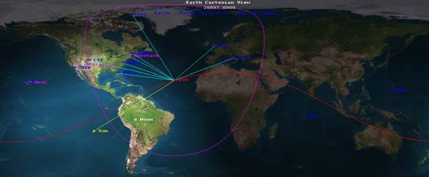
Earth Spacecraft and Sensors (ESS)                                               Paper No. GT-SSEC.D.1

                      Figure 1. DSX Flight Experiment Configuration (deployed)

               Figure 2. DSX Baseline Design, Stowed (Separation Systems not Shown)

From the earliest DSX conceptual planning, it was understood that the key to a successful program
execution was maximizing DSX’s compatibility with numerous launch vehicles. While the ESPA-based
approach makes every EELV a potential ride, not all co-manifest opportunities possess sufficient excess
launch vehicle performance needed to inject DSX into its uncommon MEO orbit. Therefore, flexibility in
the design will be maintained for as long as possible to allow repackaging DSX for flight on dedicated
launchers. Inherent in the modular approach shown in Figure 2 is the ability to separate the two modules
from the ESPA ring, and directly stack them in a vertical assembly for a dedicated launcher. The stacked
HSB configuration is shown in Figure 3, and fairing encapsulated views of DSX are shown for EELV,
Minotaur IV/V, and Falcon V in Figure 4. This modular architecture not only makes DSX reconfigurable
for various launch vehicles, but it also greatly simplifies payload integration.

                                           Page 3 of 17 Pages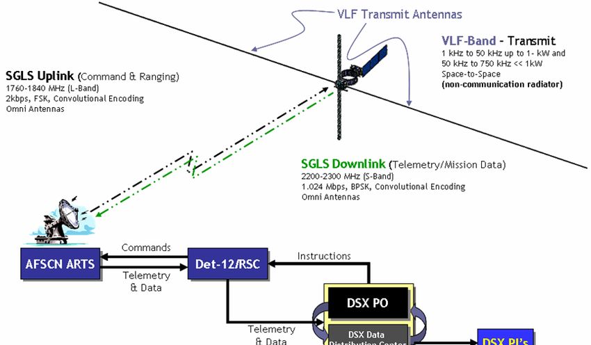
Earth Spacecraft and Sensors (ESS)                                                                                Paper No. GT-SSEC.D.1

                    Figure 3. DSX Stacked Configuration for Dedicated Launchers

                                 Figure 4. DSX Stowed, Encapsulated
           Left to right: Atlas V EELV (baseline ESPAsat), Minotaur IV/V, and Falcon V

2.1.    Ground Segment
The DSX ground segment consists of three major elements: mission control, global telemetry tracking &
control (TT&C) network, and the remote experiment sites, as shown conceptually in Figure 5.
                                                                                            Space
                                                                                           Segment
                                              DSX Mission
                                            Operations at RSC                  Space –Ground
                                              & VSES MOC                          Interface
                                                                                                         Remote
                     VAFB
                   (SLC-3E)
                                                                                                     Experiment Sites

                                                            TCP/IP Comm to
                                                            tracking network
                              • Ground control Software
                                   • Telemetry Processing
                                   • Mission Analysis
                                   • Command Generation
                                                                    Global Tracking
                                                                   Network (AFSCN)

                                        All data gets compiled & stored at MOC/DC
                                             prior to dissemination to scientists

                                        Figure 5. DSX Ground Segment Overview

                                                                    Page 4 of 17 Pages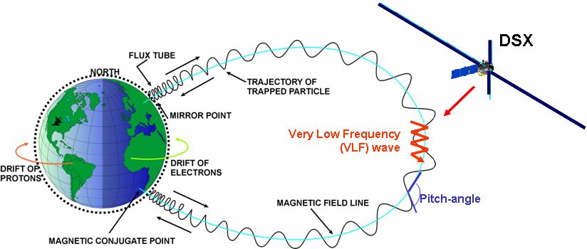
Earth Spacecraft and Sensors (ESS)                                                  Paper No. GT-SSEC.D.1

The mission will be operated out of both the Space and Missile Systems Center’s Research, Development,
Test and Evaluation Support Complex (Det-12/RSC) and AFRL’s Missions Operations and Data Center
(MOC/DC) facilities located at Kirtland AFB, NM. Det-12/RSC will provide the real-time contacts
support, schedule the Air Force Satellite Control Network (AFSCN) TT&C, and acquire both spacecraft
and payload data from the space vehicle. Commands will initially be developed from AFRL’s MOC/DC
facility where the effects will be simulated to validate proper operation. These commands will be sent to
the RSC for uplink via Space-Ground Link System (SGLS) communication protocol to the DSX satellite.
Downlinked information from the space vehicle state-of-health will be validated from the real-time
operations system located at the RSC. Data from remote experiment sites i.e., optical and radar ranges
and VLF ground installations, are coordinated at the data center. All uplinked commands and downlinked
telemetry and science data for DSX will be encrypted. In addition to SGLS communications bands, the
DSX spectrum allocation application also includes the VLF frequencies used for the wave particle
interaction experiment. The RF emissions flow for DSX is shown in Figure 6.

                              Figure 6. DSX RF Emissions Flow Diagram
All DSX data products, including real-time telemetry, stored state-of-health, stored and real-time
experiment data, and ranging information, will be sent to the MOC/DC for further analysis and data
archival. The DC will correct time tags, parse data files, collect data from remote sites (optical and radar
ranges and VLF ground installations), and permanently archive the data. Experiment data and required
spacecraft by-products will be distributed to each experiment team. DSX has applied for the necessary
spectrum allocations.
Preliminary orbit analysis performed for DSX has shown that AFSCN provides fairly continuous
coverage over the orbit. Based on the need for AFSCN to prioritize operational assets, an average of 85
minutes contact time per orbit, for a 5.3 hour orbit period (6,000 km x, 12,000 km) is assumed. Figure 7
shows the DSX orbit, along with the AFSCN, optical, and radar ground stations along its track.

                                            Page 5 of 17 Pages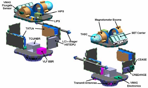
Earth Spacecraft and Sensors (ESS)                                                     Paper No. GT-SSEC.D.1

       Figure 7. DSX Ground Stations (AFSCN shown in blue, optical and radar sites in purple)

3.0 DSX Experiments

3.1.     Very Low Frequency (VLF) Wave Particle Interaction Experiment (WPIx)
The inner magnetosphere (< 10,000 km) is the region where the radiation belts, due to natural or man-
made events, are the most long-lived. Energetic electron belts, produced by these events, would dominate
the radiation environment and significantly degrade low Earth orbit (LEO) assets. Methods are being
investigated to reduce the intensity of an enhanced belt by transmitting VLF electromagnetic waves which
will pitch-angle scatter the electrons via cyclotron-resonant wave-particle interactions. Properly directed,
this electron scattering will increase the electron velocity parallel to the local magnetic field and lower the
altitude of their magnetic reflection. If the magnetic reflection is lowered to altitudes within the upper
atmosphere, collisions with the plentiful neutral particles will lead to a depopulation of the radiation belt
along that magnetic flux tube. These processes can be viewed as accelerating the natural rate of electron
loss by deliberately enhancing the VLF energy density. These processes are illustrated in Figure 8.

                          Figure 8. VLF Wave Particle Interaction Processes
Natural sources of VLF in the magnetosphere include magnetospheric hiss generated by space weather
processes and lightning-induced whistler waves propagating along field-aligned ducts through the
magnetosphere. To match current models of radiation belt dynamics to the observed behavior of
electrons, it is necessary to postulate that man-made VLF leaking into the magnetosphere from ground-
based submarine communications systems is also a significant source. Direct measurements of VLF
power have been sparse because scientific satellites with the required capability (e.g. the AF CRRES [3]
and NASA IMAGE [4] missions) have been in highly elliptic orbits with apogee > 6 Earth radii and
consequently spend most of their time outside the inner belt and slot region. Placing a VLF transmitter
and receiver on the DSX satellite will allow for a quantitative determination of the efficiency of injection

                                             Page 6 of 17 Pages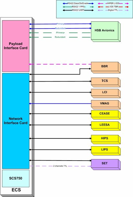
Earth Spacecraft and Sensors (ESS)                                                   Paper No. GT-SSEC.D.1

of VLF from a space-based platform and the current levels of natural and man-made VLF waves in the
inner magnetosphere. Models of ground-based VLF injection and global magnetospheric propagation will
also be validated in a controlled manner. An electron loss cone detector on DSX will provide the
capability to directly correlate changes in energetic particle distributions with injected wave power.
Accurate models of the VLF injection, propagation, and wave particle interaction processes are critical to
assess the viability of an operational space-based VLF transmission system. Measurements of the VLF
wave field will also accelerate the development of the natural radiation belt forecast models needed for
space situational awareness and mission planning. The WPIx payloads consist of four major components,
further described below.

3.1.1   Wave-Induced Precipitation of Electron Radiation (WIPER) Broad Band Receiver
The WIPER broadband receiver (BBR) is a passive receiver designed to measure the natural and man-
made ELF, VLF and LF signals in the inner magnetosphere in the range 3-50 kHz. The BBR is
electrically connected to all four deployed booms shown in Figure 1, with two channels of the BBR
measuring electric fields via the y and z-axis VLF antennas, and three more channels measuring magnetic
field about threes axes of the Triaxial Search Coil Antennas (TASC). TASC is mounted on the tip of the
+Z boom and the BBR is contained within the payload module. BBR measurements are also coordinated
with high power transmissions resulting from the WIPER transmitter, transmissions from ground based
facilities, as well as naturally occurring sources of magnetospheric VLF (i.e., lightening). The WIPER
BBR is being developed by Stanford University.

3.1.2   WIPER Transmitter and Narrow Band Receiver Electronics
The WIPER transmitter electronics portion consists of the transmitter controller unit (TCU) with an
integral narrow-band receiver (NBR) as well as two transmitter amplifier tuner units (TATU). Each
TATU electrically connects to a pole of a center-fed dipole antenna supported by the ±Y booms shown in
Figure 1. The transmitter electronics include dynamic tuning circuits, embedded within the TCU. The
VLF transmission system will broadcast up to the kilowatt level in the range 1-50 kHz and at much
smaller power levels from 50 kHz - 750 kHz by charging conductive antenna elements that run along the
Y-axis booms to levels up to 10 kV. The TCU/NBR and both TATUs are housed within the payload
module. The WIPER transmitter electronics are being developed by the University of Massachusetts-
Lowell, benefiting from significant heritage resulting for a similar payload flown on NASA’s IMAGE.

3.1.3   Loss Cone Imager (LCI)
The Loss Cone Imager (LCI) is an electron loss-cone particle detector that will provide a measurement of
three dimensional energetic particle distributions with emphasis on the measurement of the fluxes of
energetic electrons along the direction parallel and anti-parallel to the local geomagnetic field vector. The
LCI consists of two scanning heads, with ±180° motorized articulation capability, and each projected a
180° field of view fan, with each scan head position, so that together the full 4π unit sphere may be
imaged. LCI depends on data from the DC Vector Magnetometer (VMAG) for its motor pointing control
loop, and for later ground data correlation.
A separate Solid State Detector (SSD) telescope called the High Sensitivity Telescope (HST) will be
mounted on the DSX in order to obtain fluxes of energetic electrons along the geomagnetic field vector
direction. This telescope is designed to have a geometric factor of 0.1 cm2 steradian with sufficient
shielding to permit the detection of 100 particles/cm2-sec-steradian in the loss cone. The LCI is under
development by Boston University, and also benefits from heritage obtained in the development and
flight of similar instruments such as the Imaging Electron Spectrometer (IES) on Cluster.

                                             Page 7 of 17 Pages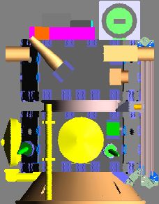
Earth Spacecraft and Sensors (ESS)                                                    Paper No. GT-SSEC.D.1

3.1.4   DC Vector Magnetometer (VMAG)
A DC fluxgate vector magnetometer (VMAG) will be used to determine the direction of the magnetic
field to better than one degree at all points in the orbit. This performance will allow the mapping of
locally measured particle distributions to global distributions. VMAG sensors will measure the DC B-
field over a 100-10000 nT range with ±0.1 nT accuracy at 20 Hz. VMAG data is also used in real-time
by the LCI, as previously discussed. VMAG will operate continuously to provide DC magnetic field and
ULF wave environment data required by the SWx MEO space particle modeling experiment, thus it
supports both WPIx and SWx experiment objectives.
The VMAG electronics will be mounted within the payload module and the fluxgate sensor will be
deployed on the tip of the –Z boom, opposite TASC. VMAG is under development for DSX by UCLA,
and is similar to other fluxgate magnetometers (shown in Figure 9) developed by UCLA and flown on
several missions.

                        Figure 9. Fluxgate Sensor (left) and Electronics (right)

3.2.    Space Weather Experiments (SWx)
With an orbit between 6,000-12,000 km, DSX will explore a large swath of the inner magnetosphere, in
particular the outer region of the inner proton belt the “slot region”, and inner regions of the outer
electron belt. This domain has remained largely unexplored due to the understandable tendency of
military, commercial, and scientific satellite systems to be located outside the intense regions of radiation,
most often at LEO or GEO. However, increasing demands for uninterrupted coverage of the Earth from
space are driving planners to consider putting satellite constellations in orbits spending significant time in
the inner magnetosphere. Current standard space particle models (e.g. AE-8 and AP-8) can be off by as
much as 50 times or more in estimating the time taken to reach hazardous dose levels in the MEO regime.
It is imperative that measurements be made of the plasma and energetic particles so that adequate
climatological, situational awareness, and forecast models can be developed to enable the successful
design and operations of systems in these new and desirable orbit regimes. Accurate environment
determination is important for DSX so that quantitative correlation with the performance of the spacecraft
and its payloads over the course of the mission may be performed.
Deficiencies of current standard radiation belt models in the inner magnetosphere include the lack of (a)
spectrally resolved, uncontaminated measurements of high energy protons (10-400 MeV) and electrons
(1-30 MeV) and (b) accurate mid to low energy (< 1000 keV) measurements of the energetic particle and
plasma environment (see Figure 10). The Space Weather instruments on DSX will address these
deficiencies. Included will be electron and proton detectors measuring both the spectral content and angle
of arrival of both species over broad energy ranges. An on-board magnetometer (VMAG, see above) will
allow for the transformation of angle-of-arrival measurements into estimates of the flux distribution with
respect to the local pitch-angle (i.e. the angle between the particle velocity and magnetic field). Local
pitch-angle distributions can then be used to estimate global particle distributions by mapping techniques
using the well-known equations of motion and magnetic field models tagged to the local measurements.
The nominal space weather sensor suite capabilities are described in detail in the following sub-sections.

                                             Page 8 of 17 Pages
Earth Spacecraft and Sensors (ESS) Paper No. GT-SSEC.D.1
Figure 10. Space Weather Data from TSX and DSP Shows Lack of Data in MEO
3.2.1 Compact Environmental Anomaly Sensor (CEASE)
Composed of two dosimeters, two particle telescopes and a Single Event Effect detector, CEASE has the
capability to monitor a broad range of space hazards from surface damage and charging (keV electrons) to
Single Event Effects resulting from >100 MeV cosmic rays and solar protons [5,6]. The angular field-of-
view for CEASE is relatively large and will not allow for pitch angle resolved measurements. CEASE
will be mounted on an exterior panel of the payload module. One change for DSX is that CEASE will
capture and downlink the full dose spectra from each dosimeter, whereas prior versions only captured six
reduced data points (two for low LET data and four for high LET data). The CEASE instrument was
developed by Amptek, Inc. and has already flown on several spacecraft. CEASE and the other SWx
instruments are shown in Figure 11.
3.2.2 Low Energy Electrostatic Analyzer (LEESA)
LEESA will measure energy fluxes and energy spectra for low energy electrons and protons (100 eV to
50 keV). These low energy particles are responsible for surface electric charging and damage to thin
films such as thin-film photovoltaics, conventional solar cell cover glasses, and coatings. LEESA will be
mounted on an exterior panel of the avionics module. It is under development for DSX by Amptek.
3.2.3 High Energy Imaging Particle Spectrometer (HIPS)
HIPS will measure electrons with energies between 1-10 MeV and protons with energies between 30 and
300 MeV. These high energy particles are responsible for microelectronics damage, displacement and
total dose damage, SEEs, and deep dielectric charging. HIPS will be mounted on an exterior panel of the
payload module. It is under development for DSX by Physical Sciences, Inc (PSI).
3.2.4 Low Energy Imaging Particle Spectrometer (LIPS)
LIPS is designed to measure the ring current particles that are important in the energy flow processes in
the magnetosphere. This particle population plays an important role in spacecraft charging and surface
damage due to sputtering. The instrument, built by Physical Sciences Inc, uses specially designed
combinations of scintillator materials to detect electrons and protons with energies between 20 keV and 1
MeV. Eight 10 degree by 8 degree field-of-view windows will provide pitch angle resolution. LIPS will
be mounted on an exterior panel of the payload module, and is also being developed by PSI.
Figure 11. Space Weather Instruments (CEASE, LEESA, HIPS, and LIPS)
Page 9 of 17 PagesEarth Spacecraft and Sensors (ESS) Paper No. GT-SSEC.D.1
3.3. Space Environmental Effects Experiment (SFx)
3.3.1 Space Environment Testbed (SET)
The SET carrier, under development by NASA GSFC provides standard mechanical, electrical, &
thermal interfaces for a collection of small flight investigations. The general areas of
investigation of the instruments carried on SET fall in the following categories:
1. Characterization of the space environment;
2. Performance improvement for microelectronics used in space;
3. Accommodation and/or Mitigation of Space Environment Effects for detectors & sensors
4. Accommodation and/or mitigation of charging/discharging effects on spacecraft &
spacecraft components;
5. Definition of mechanisms for materials’ degradation and performance characterization of
materials designed for shielding from ionizing radiation.
The first SET mission, SET-1, was recently added to the DSX experiment suite. SET-1 consists
of the following specific investigations (also refer to Figure 12):
Credance. Cosmic Ray Environment Dosimetery and Charging (Credance) measures the radiation
environment (total dose), and the charging environment for normal background and during space weather
events. Credance specific measurements include:
1. Proton flux > 40 MeV per unit solid angle
2. Charge deposition in large silicon diodes arranged in telescopes. Pulse height analysis is used to
obtain ion linear energy transfer (LET) spectra of heavy ions in the 100 MeV cm2/g to 25000 MeV
cm2/g range
3. Threshold voltage shift as a function of time to measure total ionizing dose in silicon at 2 different
shielding depths
4. Charging current at 3 different shielding depths which provides energetic electron flux measurements
at 3 energies
Its measurements overlap in part with the CEASE space weather instrument, and will provide for mutual
validation and data correlation of both instruments. Credance has been developed by QinetiQ/UK.
DIME. Dosimetry Intercomparison and Miniaturization (DIME) will measure space radiation
environments which are detrimental to space system reliability using novel dosimetry techniques. DIME
occupies two 3U card slots on the SET-1 carrier, and is being developed by Clemson University. Specific
DIME measurements include:
1. Radiation-Sensing Field-Effect Transistor (RADFET) - threshold voltage shift as a function of time;
converted to total ionizing dose.
2. Erasable Programmable Read-only Memory (EPROM) - threshold voltage shift as a function of time;
converted to total ionizing dose. Also number of single event upsets as a function of time to measure
rates as a function of radiation level.
3. Static Random Access Memory (SRAM) - hold devices at different voltages and measure single event
upsets. Change in voltage at which an error occurs is converted to dose. Also number of single event
upsets as a function of time to measure rates as a function of radiation level.
4. Linear Energy Transfer (LET) Spectrometer - pulse height spectra as function of time; converted to
LET to measure ions including protons.
5. Optically Stimulated Luminescent (OSL) Films - visible emission spectrum as a function of time to
measure micro-dose.
Page 10 of 17 PagesEarth Spacecraft and Sensors (ESS) Paper No. GT-SSEC.D.1
ELDRS. Focused on characterization of Proton Effects and Enhanced Low Dose Rate Sensitivity
(ELDRS) in Bipolar Junction Transistors (BJT), ELDRS measures space radiation induced total ionizing
dose and displacement damage on linear devices sensitive to enhanced space low dose rate effects.
ELDRS will measure base and collector currents for 24 COTS BJTs as functions of the emitter and gate
voltages and time. ELDRS is being developed by Arizona State University.
COTS-2. COTS-2 measures particle induced single event effects on a single event effects mitigation
platform in normal backgrounds and during solar storm events. COTS-2 will measure a single event
effect (SEE) on COTS FPGAs, classify the event by event type, and determine if mitigation of the effect
occurred without watchdog intervention. COTS-2 is being co-developed by NASA and CNES.
Figure 12. SET-1 (red plate is none-flight)
3.3.2 Photometers and Radiometers
DSX will fly several photometers and radiometers (see Figure 13), developed by AFRL’s Propulsion
Directorate (Edwards, AFB). Together these will directly measure changes in optical transmission,
thermal absorption and emission due to the MEO radiation environment. Coupon level testing of specific
developmental coatings intended for thin-film photovoltaics may also be performed using these sensors.
Figure 13. Radiometers (left) and Photometers (right)
3.3.3 Mechanical Packaging of Payloads
The design for both the avionics and payload modules, and mechanical arrangement and packaging of
payloads within the payload module has been performed by MicroSat Systems, Inc (MSI). The resulting
payload module equipment layout is shown below (Figure 14).
Figure 14. Mechanical Packaging and Layout of Payloads
Page 11 of 17 PagesEarth Spacecraft and Sensors (ESS) Paper No. GT-SSEC.D.1
4.0 Concept of Operations (CONOPS)
The DSX mission starts with launch as a secondary payload on an EELV. During launch DSX is in a
minimally powered state, so that it may detect a separation signal. Following separation of the primary
payload from atop DSX, it is likely that the EELV upper-stage would need to be re-started in order to
inject DSX into the correct orbit. At this point DSX then separates from the upper stage. Upon detection
of the separation signal, DSX will undergo a series of autonomous scripted commands to initialize the
bus. After acquisition of signal from the ground, and verification of nominal operation, the bus solar
arrays deploy from the avionics module, and the attitude control system is activated in a sun-safe mode in
order to orient the spacecraft into a power-positive attitude. Ground controllers will then perform various
checks to verify the spacecraft state of health before initiating any boom deployments. Booms will be
deployed in pairs: y-axis pair and z-axis pair, to minimize inertial imbalances. During boom deployments
the attitude control system is placed in a less responsive mode in consideration of the fact that during
deployments the center of pressure and moments of inertia of the spacecraft will vary significantly. Upon
completion of these deployments, additional in-orbit tests are performed before the spacecraft assumes an
operational mode. The scheduling of the sequence of events from separation though entering the
operational phase is being developed, but is expected to be accomplished in under one week.
Once the spacecraft is operational, routine commanding and data collection will be initiated as discussed
in Section 2.1 (Ground Segment). Because spacecraft resources (namely power and data volume) are
limited, and because certain experiments can only be operated at certain times, experimental payloads are
duty cycled to fit within the capabilities of the spacecraft. In general, SWx instruments will operate
continuously with only limited ground intervention, such as occasional commanding to adjust threshold
and gain settings. They would only be turned off under low power conditions. The SET-1 payload will
have two modes of operation, a low power mode where only Credance is powered and collecting data,
and the normal mode where all its experiment investigations are operating. While in normal mode
measurements take place on a set interval, with some measurements triggered by the on-board orbit
propagator, which will indicate to SET-1 the timing of ascending and descending node crossings. The
most demanding constraints are associated with the WPIx measurements, since these consume the greatest
power (during the high power Whistler transmission mode), and also generate the most data, as collected
from the broadband receiver. For science reasons, the high power transmissions can be constrained to
occur when the spacecraft is within ±20° latitude of equatorial, and because of power limitations the
transmission durations will generally be limited to no more then 30 minutes per orbit. Figure 15 is a plot
of payload power demand over a period of five days, prepared by Planning Systems, Inc. A more detailed
year-long mission timeline is being prepared to plan all DSX operations and coordinate ground resources.
700
600
500
400
Watts
300
200
100
0
0 1 2 3 4 5 6 7
Days
Figure 15. Payload Power Profile – A Week in the Life of DSX
Page 12 of 17 PagesEarth Spacecraft and Sensors (ESS) Paper No. GT-SSEC.D.1
5.0 Technical Performance Measures (TPM)
Since its earliest stages of development, the DSX program has implemented a mass and power control
process, and carefully tracks these metrics. A master equipment list has been developed to identify every
equipment or structural element of the spacecraft, with mass and power consumption estimates,
contingency estimates, and allocations. Summary forms of these budgets are presented in Tables 1-2,
respectively. Note that the end-of-life (EOL) power generation reduction indicated in Table 2 is a result
of photovoltaic degradation due to the severe MEO radiation environment.
The upper mass limit requirement for DSX, in the absence of a specific manifested launch vehicle with
identified throw weight margins, was simply determined as the mass of a fully loaded ESPA ring, or
1205.6 kg. However, DSX’s true mass margins are measured against launch vehicle performance. To
that end, launch vehicle performance studies were conducted for EELV ESPA as well as dedicated
launches on Minotaur IV/V and the SpaceX Falcon V (in development). The results of those studies are
presented in Table 3.
Table 1. Mass Budget Summary (EELV ESPA Case)
Equipment Basic Mass (kg) Mass w/Contingency (kg)
Total Vehicle, Separated Mass 466 536
Avionics Module (AM) 148 169
Attitude Control (except IMU) 29 31
Avionics (C&DH and PMAD) 9 10
Electrical Power Subsystem 41 46
Thermal Control System (TCS) 4 5
Telecom 7 7
Experiment Computer (ECS) 7 9
SWx (LEESA) 8 10
Harnesses 9 10
AM Structure 35 40
Payload Module (PM) 139 170
WPIx (WIPER, VMAG, LCI) 41 52
Y and Z booms 16 18
SWx (CEASE, LIPS, HIPS) 12 16
SET-1 13 17
Harnesses 12 16
IMU 1 1
TCS 4 5
PM Structure 40 46
Primary Structure 179 197
ESPA 122 128
Separation Systems 28 32
Harness 13 18
Misc. 16 19
Maximum per ESPA Port 181
Max. ESPA Populated 1206
Table 2. Power Metrics and Budget Summary
Array Power Generation (W)* 1320 BOL, 850 EOL
Battery Capacity* 60 Amp-hr
Bus Steady-State Avg. Power (SSAP, W)* ~300
SSAP Available for Payloads (W)* ~350
Composite WPIx Exp. SSAP (W) 115 (normal), 720
(HP transmit mode)
Composite SWx Exp. SSAP (W) 23
Composite SFx Exp. SSAP (W) 55 (all experiments), 26
(Credance only)
Total Payload Heater Power (W)* 100 (cold case)
*Data provided by MSI
Page 13 of 17 PagesEarth Spacecraft and Sensors (ESS) Paper No. GT-SSEC.D.1
Table 3. DSX Launch Studies Summary
Launch Option S/C Separated LV Performance, Reference Orbit Mass Margin Study Performed by
Mass (kg) Mass to Orbit (kg) (kg)
EELV, Atlas V-401, 466 (basic) 536 865 5,000x11,000 km 329 (min.) USAF Det. 12 (STP),
DMSP Co-manifest (max.) @117° inclination 399 (max.) Lockheed Martin
Minotaur IV, 343 (basic) 395 500 6,000x6,000 km N/A RSLP, Orbital
dedicated (max.) @28.5° inc.
Minotaur V, 343 (basic) 395 313 6,000x21,000 km -82 (min.) - RSLP, Orbital
dedicated (max.) @28.5° inc. 30 (max.)
Falcon V, dedicated 343 (basic) 395 1000 6,000x12,000 km 605 (min.) SpaceX
(max.) @9° inc. 657 (max.)
The current DSX contingency mass estimate of 536 kg allows 670 kg of unallocated mass margin to the
above described ESPA limit, but only 329 kg against the launch vehicle performance margin for a
specific case of an EELV launch: co-manifest of DSX with a DMSP primary satellite on an Atlas V (401)
launch vehicle. The stacked configuration of DSX is significantly lighter at 395 kg with contingency, due
primarily to the mass associated with the ESPA ring no longer being carried. However Table 3 shows
that that of the dedicated launch options, only Falcon V shows sufficient performance margin. Minotaur
V has a negative margin of at least 30 kg; as such a more refined performance analysis may yield
sufficient performance if in conjunction a severe mass reduction program on DSX were implemented.
6.0 Spacecraft Driving Requirements
The science objectives of DSX impose certain mission specific driving requirements on the design of the
spacecraft bus and payloads. These are identified here. The nominal MEO orbit (6000 x 12000 km, mid-
inclination), results in a fairly severe radiation environment, because of prolonged residence time in the
upper Van Allen belts. The total ionizing dose (TID) for the mission is approximately equivalent to 10
krad/year behind 8 mm of Aluminum absorber shielding. The results of radiation dose analyses
performed for DSX are shown in Figure 16. The implication of this is that all DSX equipment must be
designed to survive the radiation environment, through the use of shielding, selection of radiation and
SEU tolerant or hardened components, or a combination of these approaches.
Figure 16. Total Ionizing Dose for DSX Mission
With respect to flight orientation, the attitude control system must provide 3-axis stabilization, maintain a
power positive attitude throughout the mission, and orient the spacecraft such that the VLF antennas are
aligned normal to the local magnetic field lines, for the duration the spacecraft is within ±20º of equatorial
(i.e., when VLF propagation experiments and measurements will be performed). Pointing requirements
are fairly relaxed with a 2º control and a 1º knowledge requirement deemed to be sufficient.
Page 14 of 17 PagesEarth Spacecraft and Sensors (ESS) Paper No. GT-SSEC.D.1
7.0 Responsive Enabling Technologies
Historically, spacecraft payloads have been produced via end-to-end development of the entire payload
system as well as significant development of key satellite bus components with interfaces to the payload
such as the flight computer and power management system. As part of this effort, a considerable fraction
of the engineering development required to produce a working system is devoted to specifying,
developing, and testing the components designed to perform payload functions that, in general, fall under
the category of payload interface electronics for data acquisition and control. This approach is not
conducive to rapid response missions because it depends on monolithic integration methods. Monolithic
integration of a satellite involves assembly of many components simultaneously. This can present an
integration and test nightmare, where debugging problems found in system level testing and routine
maintenance of the vehicle can be very complex and costly to perform.
Modular integration on the other hand allows major subsystems and payload modules to be fully
integrated and functionally tested separately. System level testing can be performed in a “FlatSat”
configuration, pre-integration where the subsystems are wired together using test harnesses to verify
connectivity as well as performing closed-loop performance tests. This allows for much faster isolation
of problems and shorter integration spans.
DSX maximizes the benefits of modular integration via an architecture that requires that all devices
adhere to a standard interface for control and communications (electrical, power, command &
communications protocol). This is enabled by the use of dual-redundant network interface cards (NIC) in
the Experiment Computer System chassis that provide for command and data interface between the flight
control computer and all payloads. Rather than a single on-board computer responsible for handling all
spacecraft functions, DSX unburdens the main spacecraft computer with the payload related operations,
by providing a dedicated payload interface computer, or Experiment Computer System (ECS), under
development by Planning Systems, Inc. for DSX. This architecture decouples the requirements of the
flight computer with the design of the payloads, allowing for a completely standardized spacecraft flight
computer, almost independent of payload requirements. The highly capable ECS design is also
generalized in nature, so that it can handle a wide range of payload types and classes simultaneously, with
low data latency. An ECS block diagram is provided in Figure 17., below.
Figure 17. Experiment Computer System (ECS)
Page 15 of 17 PagesEarth Spacecraft and Sensors (ESS) Paper No. GT-SSEC.D.1
These modular avionics technologies complement the modular reconfigurable mechanical design, and
together represent a path finder for future rapid-response spacecraft. With this approach, the DSX
avionics module can be designed, integrated, and delivered before all the payloads have completed their
development cycle, or even been selected. The next evolutionary step for this technology involves adding
networking capabilities and enhancing the flight control computer so they are pre-programmed to self-
configure spacecraft subsystems, components, devices, and payloads. This allows for rapid configuration
and integration of off-the-shelf, modular spacecraft consisting of pre-defined building blocks “on the fly”.
8.0 Summary
AFRL’s DSX mission is well underway. The Spacecraft Systems Requirements (SRR) was completed in
the fall of 2004. Avionics, spacecraft bus, and Experiment Computer System Preliminary Design
Reviews (PDR’s) were completed in 2005, and most payloads will have reached the PDR milestone by
the first quarter of 2006. With the fully integrated avionics module, depopulated payload module, and
ESPA ring scheduled for delivery to AFRL in the first quarter of 2007, and all flight payloads delivered
for AI&T by April 2008, DSX is currently on track to be launch ready by late FY08.
The DSX mission will provide an important database from which future designers of space missions
intended to operate in the MEO environment can rely. Beyond the inherent value of the scientific
experiments, DSX is also path-finding a new, responsive approach for integrating spacecraft. The ESPA
platform ensures affordable and frequent opportunities for launch. In addition, the combination of a
dedicated payload/experiment computer and modular integration approach, allows a “standard” host
spacecraft bus to be used, limiting the development risk to the experiments alone.
9.0 Acknowledgements
The author would like to acknowledge the contributions of numerous persons and organizations to this
paper. The mission and experiment design, spacecraft architecture, and requirements are the result of two
years of intensive activities of many persons at AFRL, Space Vehicles Directorate. Much of the detailed
payload and instrument descriptions were adapted from information originating in design reviews and
other materials provided by MicroSat Systems (MSI), Inc., Planning Systems, Inc., Boston University,
UCLA, Stanford University, Lockheed Martin, the University of Massachusetts at Lowell, Amptek, Inc.,
Physical Sciences, Inc., NASA Goddard Spaceflight Center (GSFC), AFRL Propulsion Directorate, and
Detachment 12/Space Test Program (STP).
Specific content provided by others includes many of the images in this paper. Specifically all stowed
and deployed views of the spacecraft (Figures 1, 2, 4, and 14) were provided by MSI, Figures 3, 15, and
17 were provided by Planning Systems. Images of VMAG components (Figure 9) were provided by
UCLA. In Figure 11, images of CEASE and LEESA were provided by Amptek, and those of HIPS and
LIPS were provided by Physical Sciences. The SET-1 image (Figure 12) was provided by NASA GSFC.
Page 16 of 17 PagesEarth Spacecraft and Sensors (ESS) Paper No. GT-SSEC.D.1
10.0 References
[1] Goodwin, J.S. and Wegner, P., “Evolved Expendable Launch Vehicle Secondary Payload Adapter –
Helping Technology get to Space,” AIAA Space 2001 – Conference and Exposition, AIAA Paper 2001-
4701, August 2001.
[2] EELV Standard Interface Group, Evolved Expendable Launch Vehicle Standard Interface
Specification Version 6, Kendall, Randy, Ed., September 2000.
[3] Gussenhoven, M.S., Mullen, E.G., and Brautigam, D.H., “Improved Understanding of the Earth’s
Radiation Belts from the CRRESS Satellite”, IEEE Transactions on Nuclear Science, April 1996, Vol.
43, no. 2, pp.353-368.
[4] Burch, J.L., “IMAGE Mission Overview”, Space Science Reviews, January 2000, vol. 91, no. 1-2,
pp.1-14.
[5] Dichter, B. K., J. O. McGarity, M. R. Oberhardt, V. T. Jordanov, D. J. Sperry, A. C. Huber, J. A.
Pantazis, E. G. Mullen, G. Ginet, and M. S. Gussenhoven, “Compact Environment Anomaly Sensor
(CEASE): A Novel Spacecraft Instrument for In Situ Measurements of Environmental Conditions,”
IEEE Trans. Nucl. Sci., 45, 2800, 1998.
[6] Dichter, B.K., Turnbull, W.R., Brautigam, D.H., Ray, K.P., Redus, R.H., “Initial on-orbit results from
the Compact Environmental Anomaly Sensor (CEASE),” IEEE Trans. Nucl. Sci., vol. 48, pp. 2022 -
2028 Dec. 2001.
The following references are not directly called out in this paper, but nonetheless provide background
material on related subjects:
[7] Martin, M., Klupar, P., Kilberg, S., Winter, J., “TechSat 21 and Revolutionizing Space Missions
Using Microsatellites,” USU Small Satellite Conference, 2001.
[8] Winter, J. and Anderson, N., “Distributed Aperture Implementation On the TechSat 21 Satellites,
IEEE Aerospace Conference, 2003.
[9] Cohen, D., Greeley, S., Kemper, S., King, J., Davis, L., Spanjers, G., Winter, J., Adler, S., Easley, S.,
Tolliver, M., “The Deployable Structures Experiment: Design of a Low-Cost, Responsive R&D Space
Mission,” Paper #SSC04-I-6, 18th Annual/USU Conference on Small Satellites, Logan, UT, August
2004.
[10] Cohen, D., Wieber, J., King, J., Kemper, S., Stephens, S., Davis, L., Spanjers, G., Winter, J., Adler,
A., Easley, S., Tolliver, M., Guarnieri, J., “The SSTE-4: DSX Flight Experiment: Design of a Low-
Cost, R&D Space Mission with Responsive Enabling Technologies,” Paper #2005-3004, AIAA 3rd
Responsive Space Conference 2005, Los Angeles, CA, April 2005.
Page 17 of 17 PagesYou can also read