DESIGN CONSIDERATIONS OF TUBULAR CONNECTIONS: AN EXAMPLE THROUGH THE SINGAPORE SPORTS HUB NATIONAL STADIUM ROOF
←
→
Page content transcription
If your browser does not render page correctly, please read the page content below
DESIGN CONSIDERATIONS OF TUBULAR CONNECTIONS:
AN EXAMPLE THROUGH THE SINGAPORE SPORTS HUB
NATIONAL STADIUM ROOF

Jane Nixon1, Richard Andrews2, Peter Marshall3

ABSTRACT:. The new 55,000 seat National Stadium (NST) of the Singapore Sports Hub is due to be
completed in 2014. The NST roof is a highly efficient dome with a span and raise of 310m and 85m, supporting
a movable roof. The structure formed by a series of criss-crossing triangular trusses made up of circular hollow
sections (CHS), producing clean lines in the architecturally exposed structure. Connections needed to consider
fatigue plus ultimate limit design. This, with preference from the fabricator, lead to the connections being
formed profile cut tube to tube connections. Historically the design of such profile connections is based on
plastic design using semi-empirical formulas. While this leads to a very efficient design, published data is often
only applicable to simpler framing/geometry and assumed load paths. As well as complicated 3D geometry, the
NST Roof is a highly refined efficient structure leading to limited repetition in connection geometry and loading.
An innovative application of a variety of design methods was used to develop a series of design strategies for
the tubular connections. This included using approaches from CIDECT and AWS (in particular the multiplanar
parameter), which considered possible failure mechanisms typical in CHS connections and the load path
through the connection. On highly complex and congested connections, finite element analysis was used, also
requiring an understanding of materials to determine limiting strain and acceptability criteria for design.

This paper will discuss this approach to design, balancing high-level technical design with delivery
requirements for the project

KEYWORDS: CIDECT, AWS, WELDED CONNECIONS, CHS, DOME STRUCTURE

1
  Jane Nixon, Arup, level 10, 201 Kent Street, Sydney, Australia. Email: jane.nixon@arup.com
2
  Richard Andrews. Arup, level 10, 201 Kent Street, Sydney, Australia. Email: richard.andrews@arup.com
3
  Prof Peter Marshall, Centre of Offshore Research and Engineering, National University of Singapore,
 email: cvempw@nus.edu.sg
1 INTRODUCTION
The Singapore National Stadium (NST) will form 2 OVERVIEW OF ROOF
the centre piece to the new Singapore Sports Hub STRUCTURE
and lies in the heart of the 35ha sports precinct (ref
Figure 1) The dome structure is formed by a network of
triangular primary arching trusses spanning over
The roof, at a 310m clear span, will be the largest the bowl structure. They vary in both depth and
covered dome roof in the word and at around width with a minimum depth of approximately
120kg/sqm of steel over the footprint area is an 2.5m at the base of the roof and a maximum depth
extraordinarily efficient structure. of approximately 5.0m at the centre of the dome.
The thrust of the dome is balanced by a 6m wide by
1.5m deep post-tensioned concrete ring beam.
These primary trusses are then linked together by a
series of triangular secondary trusses which directly
supports the cladding. The primary and secondary
trusses all work together to form a very stiff 3D
space frame dome structure.
There is an opening in the roof which is
approximately 220m long by 82m wide over the
football pitch. The roof directly supports the
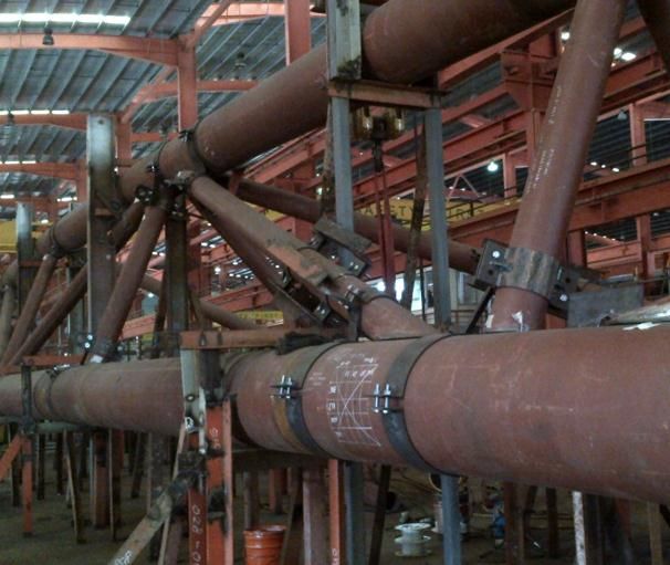
Figure 1: Architectural visualisation of the National movable roof, which opens and closes over this
Stadium opening. via a series of ‘bogies’ running on the
parallel ‘runway trusses’ that span perpendicular to
A key feature of the new NST roof is the the pitch axis (ref Figure 3)
retractable roof which will provide flexibility of the
stadium usage, as well as contributing to the
functionality of the “bowl cooling” provided to
each and every seat in the stadium.
This paper provides an introduction to the roof
structure, and then focuses on challenges and
considerations that contributed to the form of
connections and shaped the philosophy developed
for the connection design.
Figure 3: Section through the National Stadium
Key parties involved in the design and construction
of the project:
All trusses are 3D triangular trusses fabricated from
Architectural Concept and Sports Venue Designers grade S355 steel CHS sections with chords sizes of
- Arup Sport 356, 457 and 508 diameter, and bracing ranging
Architects - DPArchitects from 139.7 to 273 diameter.
Structural Engineers – Arup
Main Contractor – DSPL Sing The roof structure was developed with parametric
NST Roof Steel Contractor - Yongnam design software developed for the project to allow
for exchange and optimisation of the framing both
structurally and architecturally.
In addition to selfweight a key consideration in the
design was the wind loading. An Influence
Surfaces method was used to determine the critical
simultaneous patterned wind load across the roof.
This produces a very refined specific wind load.
Through this method, and considering every
member was optimised, a large number of load
cases were needed to be considered to ensure the
critical actions for individual members across the
roof were captured.
Figure 2: Architectural visualisation of the inside of
the National Stadium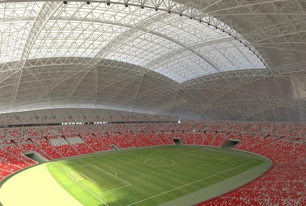
The other key consideration in the design was the Ease of fabrication: Fabricator’s
movable roof which consists of two moving panels preference for profile cut members rather
also formed by CHS sections. As well as needing to than fabricated plate nodes
consider different configurations of the movable Ease of design: Designs with clear load
roof, this opening and closing of the roof generates path and the ability to design using
varying or fatigue loads in the fixed roof framing published methods are to be preferred.
which need to be considered in the design of the
roof. As typical with long span roofs the weight of the
framing including the weight of the connections is
For further information on roof design and methods the dominating load case. Hence minimising the
refer to paper by King [1] for further information. weight of the connections was also a key
requirement for the connection design.
Under uniform loads trusses are acting like braced
arches with large compression chord forces and 3.2 FORMS CONSIDERED
much smaller brace forces. However under non-
3.2.1 Plated solution
uniform loading and in particular the different
A plated or gusseted joint was first considered. In
positions of the movable roof, and trusses across
the buildings/onshore industry this is traditionally a
the opening of the roof, the trusses resist the
more familiar form which is thought to be easily
loading through a more traditional flexural truss
designed following load paths through the
behaviour.
connecting plates. Bolted connections were also
indicated at the time of tender to allow for
Through the framing geometry and optimizing
flexibility of erection. (ref Figure 4)
techniques (both in member sizing and wind
loading) the structure is a highly refined light
weight structure.
This contributed to the challenge of the connection
design leading to a large number and variety of
connections in both geometry and complexity, as
well as the joining member being close to fully
Figure 4: Initial concepts investigated
utilised. In the fixed roof, even though a plane of
symmetry exists for the structure, 2,500
connections were each individually designed, each While applicable for the simpler connections, such
with a different geometry and loading. a gusset plated solution becomes challanging for
the more conjested nodes with multiple bracing.
Once the framing was finalised the structural These connections occur at the intersection of
analysis model was then linked to Tekla BIM trusses with mutilple interesting chords which need
model from which all the construction drawings to transfer large forces through the connection
were produced. This model was then issued to the similtaniously. Hence as well as “juggling” with
fabricators. Through processes and setup of the the geometry of the connection, thick heavy plates
Tekla model, designers and fabricators were able to are required to transfer the force through the
“talk in the same language” across the job, a key connection.
requirement considering the magnitude of the job
and information required to define the detailed A “ball” or some form of casting was briefly
design and connections across the roof. considered. However due to the geometry of the
framing a very large “ball” would be required to
remove the conjestion of the incoming framing.
3 FORM OF CONNECTION This would have an impact on the architecture of
3.1 FACTORS CONSIDERED the roof framing. Additional coverplates potentially
A number of different connection forms were would be required to hide the form of the
initially investigated for the complex geometry of connection to maintain the clean lines of the
the tube-to-tube connections of the roof. Three key framing required by the architecture (ref Figue 5).
factors were assessed when selecting the
connection detail to use: Such casting would require time to be developed
during the fabrication process and then to be tested
Fatigue sensitivity: Use of stiffener plates,
to verify strength and material performance. This
slotted plates and cruciforms within
was not considered feasible considering the
connections can greatly reduce the fatigue
program and delivery requirement of the project
life of connections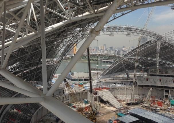
Arrangement of external plates/stiffeners

Figure 5: Initial concepts investigated

From intial investigations it was expected that due
to the loads and geometry in the more conjested
nodes, a plated connection with thick plates and
                                                        Internal gusset plate    Internal ring stiffeners
stiffiners would be required driving up the weight
                                                       stiffeners
of the connections. It is noted that a structure and
connections using hollow sections is usually lighter   Figure 4: Alternative strengthening solutions
than a similar construction formed with open           considered
sections or plates. (ref [2]).

3.2.2 Stiffened Chord                                  3.2.3 Profile cut CHS and thickened can
As mentioned the roof is highly refined with many      A connection formed from one thickened member
of the members close to utilisation, hence some        through the connection and profile cutting and
form of reinforcing was required to strengthen the     welding all other members to it was selected as the
can and transfer the force through the connection.     preferred fabrication option and the least fatigue
                                                       sensitive detail, although more challenging to
Strengthening solutions in the form of gussets or      design, following offshore oil & gas structures
addition stiffeners were briefly investigated.         guidelines. The thickened main member through
External stiffeners had the potential to affect the    the connection is referred to as a “thickened joint
architecture while internal stiffeners would be        can”. (Figure 5)
difficult to fabricate, with issues of tolerance and
                                                              Thickened can
alignment. (Figure 4)

As soon as stiffeners are added to such a profile
connection, “hard points” or stiff points are then                                                 Member set
created within the connection leading to stress                                                    out node
concentrations in the connection and a reduction in
ductility (further discussed in [10]).
                                                                                               1.25D(min)
The frame analysis of the roof had been carried out
assuming that the chord is continuous with pin-         Chord,
ended braces. This is usually verified through the      Diameter   D              1.25D(min)
ductile nature of the connection, for example a
classic welded profile cut connection. The stiffer
connection created by such additional plates or        Figure 5: Form of connection with thickened can
gussets can raise questions on secondary moments
that may then need to be reconsidered in the           Within the primary trusses chord members range
framing design.                                        form 457x10 to 457x50 and 508x12 to 508x50,
                                                       with secondary truss chord range from 355.6x8 to
For such a form of connection there is limited         355.6x22 CHS. Through the design carried out
published guidance on the design and it was            maximum thickened can section of 457x70, 508x80
expected that the design would have to resort to       or 355.6x25 respectively. While thick cans were
time consuming finite element analysis (FEA) to        required in some locations it is noted that welding
gain confidence in behaviour and verify capacity of    size was governed by the incoming members and
such stiffened connections.                            not the can size.

                                                       Such a detail allowed for a clean simple form of
                                                       connection with less welding and fabrication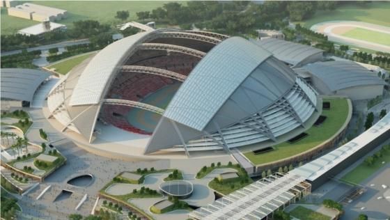
complexity that can be associated with the aternate
forms above.
Due to the the relatively low number of roof
open/close cycles and form selected fatigue is not
typically governing, and this paper discusses
strength design and methodology adopted
3.3 MATERIAL AND FABRICATION Group 1 -- Typical truss connections
55% of the connections across roof
The welded form of the connection meant care was broken into 3 topological detail sub-types
taken to ensure material was provided with each with various sizes and angles
satisfactory toughness and ductility in the material considered
and weld zone. Sub-grade of thicker sections were
provided to BS5950 and EC3 1-10.
All braces into the connection were full penetration
welded. Full strength fillet welds used in areas of
intersecting braces with small local dihedral angles,
where full penetration weld could not be provided.
The progression of weld and joint geometry varies
with local dihedral angle in going around each
Group 2 -- Secondary to primary connections
brace end [9]. Fatigue structures and in particular
35% of the connections across roof
in the offshore structure practice imposes stringent
broken into 15 detail sub-types
quality control on automated brace cutting,
connection fit-up, and 6GR tubular welder
qualification, in order to achieve sound “CJP”
welds with small groove angles and reduced weld
volume. Recent work at NUS has suggested more
forgiving PJP+ details with CJP equivalency [3, 4]
Group 3 -- Junction nodes or very congested
connections, some with thickened branch
member ends
10% of the connections across roof
broken into 100 detail sub-types
The difference in geometry between the groups
meant that different design approaches were
required for design.
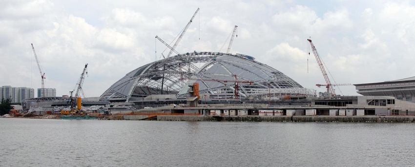
Figure 5: Section of truss with profile connections 4 BEHAVIOUR AND DESIGN
during fabrication
CIDECT [5] is one of the most widely recognized
references on CHS connection design for onshore
buildings. Due to the highly plastic and non-linear
3.4 GROUPS OF CONNECTIONS ACROSS behavior of unstiffened direct CHS connections,
THE ROOF the design and capacities are based on semi-
Once form of connection was established the empirical formulas derived through testing. Highly
connections in the roof were then divided up into detailed and complex finite element models are
three groups based on geometrical complexity and being used to extend CIDECT rules. However as a
location on the roof. Within these groups nodes highly refined and advanced FEA model is required
were classified into detail types depending on the to predict the same similar capacities to test results,
number of braces and complexity associated with CIDECT formulas remain the most effective way
each connection. to design highly efficient CHS connections.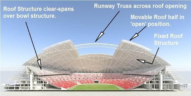
Roof members were designed to BS5950 [6].               Table 1: Faliure Mechanism terminology between
Section, material and geometry generally satisfied      CIDECT and AWS
the validity requirements of CIDECT and design of                        CIDECT              AWS
the roof was carried out, in accordance with the         Ovalising       Chord               Punching
CIDECT philosophy of moment-free bracing,                and general     plastification      shear
typically coming to a common node point.                 collapse
                                                         Local           Punching shear      Material
However it was the variety in load path, number of       material                            failure
braces, congestion and 3D behaviour of the               failure
connections that meant connections often did not
satisfy CIDECT descriptions and further                 By using empirical formulas or CIDECT/AWS
codes/guidelines were investigated.                     with methodologies that could be written into excel
                                                        or programming code the amount of automation of
Design methodology was also influenced and              the design could be maximized.
developed using Eurocode 3 [7], API RP2A [8],
and AWS D1.1 [9], all of which share overlapping        The connections were classified on the arrangement
committee membership and database as CIDECT.            of bracing using simple maths. A script was
Eurocode 3 provides the same formulas but then          developed that was able to sort through the roof
expands on and describes failure mechanisms that        geometry and classify each node in the roof to a
need to be checked providing a useful reference for     group and sub-type of connection, plus out line
failure mechanisms that were used in review and         methods of moving bracing, which could then be
development of all connection groups. API and           communicated and carried out by the fabricator in
AWS describe the practice developed initially for       the fabrication model.
very large tubular offshore structures.
                                                        Another aspect which influenced design method
As described the roof structure is a highly efficient   was the need to design to envelope loads. Due to
refined design. Both the framing and refined            the refined loading in the roof design, members the
loading (in particular wind) contributes to this        roof were designed for over 1,500 load cases in
efficient design but then creates challenges in load    each of the different configurations (movable roof
paths when trying to consider the connections in        intermediate positions and variation in support
the classical CIDECT load paths (eg a balanced K)       stiffness were each checked over 6 models, giving
as the connection would see a range of load             a total 6x1500 load cases ). While this can be
distributions which would then be made up of a          managed for one-at-a-time member design, it was
series of part K, part Y and part X load                impractical for the connection design on the tubular
                                                        dome project. Consider 2500 connections, having
This was further amplified when considering the         up to 14 interacting members, each subjected to
3D behaviour of the joint. To ensure a robust load      6x1500 load cases – together with a design process
path was followed through the connection and 3D         which was not a priori codified and easily
interaction was covered, the AWS [9] was used to        automated.
develop design methods on the more complex
connections.                                            Research into the design methods and considering
                                                        the 3 groups described above the following design
In particular the AWS assisted in considering load      approaches, in order of preference, were applied to
path through overlapping congested connections          the different groups of connections across the roof:
and the 3D multi-planar behaviour through its
ovalising parameter alpha.                                  1.   CIDECT European building code with
                                                                 conservative assumption on mulitplaner
Both the AWS and CIDECT check for the same                       correction factor
failure mechanisms but have subtly different                2.   Capacities calculation in accordance with
approach to checking and terminology in checking                 AWS and API criteria for very large
these failure mechanisms. In this paper we will                  tubular structures
generally be following the CIDECT terminology               3.   Detailed inelastic Finite Element Analysis
unless noted otherwise.                                          (FEA)

                                                        The API-AWS joint-can ovalising criteria for
                                                        multiplanar connections are given in terms of the
                                                        ovalising factor α (alpha), computed with an
                                                        influence function giving the combined ovalising
                                                        effect of all braces present, versus that of the
                                                        reference branch member being assessed.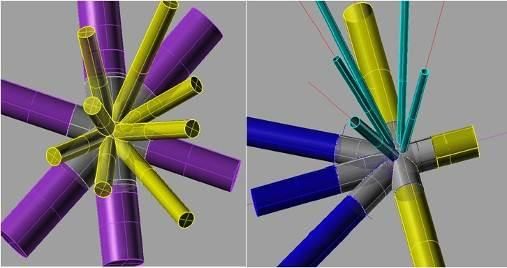
of balanced and unbalanced loading on the
Standard connection types assume alpha values            connection to be considered to ensure the
approaching 1.0 for closely spaced K-joints, 1.7 for     enveloped loads were captured in the consistent set
T-joints, and 2.4 for X-joints. For more adverse         of load/s checked in the design. The possible load
multiplanar joint situations, alpha can be as high as    paths within a KK connection is shown in Figure 6.
3.8.    The AWS chord plastification capacity
formula contains a term 1.7/α, and API simplified        Multiplanar effects can be significant to the
stress concentration factors (SCF) for fatigue are       connection capacity as noted in the paper by Lee
proportional to alpha. These considerations are          and Wilmshusrt [11], highlighting that for a KK
presented more fully in API and AWS, in their            joint under antisymmetrical load the capacity can
Commentaries, and by Marshall [10].                      be as low as 60% of the symmetrical load capacity.
                                                         CIDECT only provides guidance of multiplanar
                                                         effects on a very limited set of connection
4.1 GROUP 1 - TYPICAL TRUSS                              geometry and load distributions.
    CONNECTIONS
Over half the connections in the roof were single        Considering possible load path and behavior of the
chord with geometry of brace arrangements that are       structure, an equivalent reduction factor to apply to
consistent with the CIDECT K, T or KT, KK                the CIDECT uniplanar joint capacity was
descriptions.                                            determined, bench marking to the AWS and its
                                                         ovalisation α factor.
A decision was made early on that where possible                                        Classic symmetrical KK-
bracing was moved to ensure CIDECT minimum                                              load path
gap and overlap requirements were achieved. This                                        (assumed in CIDECT)
meant that connections could be designed though
simple design rules and hence automated design
without the need of FEA.

The reason for this requirement is that the overlap
is a much stiffer load path than radial loading of the
chord and therefore will attract much of the load at
elastic levels. A small overlap may lack the                                                  Anitsymmetrical KK-
ductility required to avoid failure before the rest of                                        load path, due to
the connection catches up. The CIDECT minimum                                                 torsion or side shear
overlap for brace pairs of 25% is adopted.               Example of some of the theoretical
                                                         pattern of balanced/unbalanced
                                                         loads that could occur
The minimum gap limitations in CIDECT are
provided to “ensure that there is adequate clearance
to form satisfactory welds’. Following discussions       Figure 6: Possible mutiplanar load path in classic
with the fabricator it was agreed that for thicker       KK connection. Such possible permutations of load
sections 20mm was an adequate clearance and so a         path is amplified as more braces come into the
minimum gap of the lesser of the sum of the brace        connection
pair tube thicknesses and 20mm is adopted. It is
also noted that for fabrication a gap connection is
preferred.                                               4.2 GROUP 2 – SECONDARY TO PRIMARY
                                                         As more braces come into the connection the
In accordance with CIDECT philosophy, it is not          geometry and possible load path combinations
necessary to re-analyse the roof model with the          reaches another level of complexity and the
eccentricities included, but simply add additional       methods above in the extraction of the CIDECT
moment to the chord design actions. In the majority      guidelines becomes less applicable. In this case
of connections the additional moment was                 AWS guidance and methodology was more
relatively minor and was accommodated in the             applicable.
current member capacity.
                                                         The CIDECT design guide references AWS D1.1
While the geometry of the connections is a               for multiplanar effects.…Where the brace loading
recognisable CIDECT form, they did not have the          arrangement can act to suppress first mode
classic load distribution. Enveloped loads were          ovalisation of the chord and therefore result in an
given for the connection design, therefore the load      increased capacity, the AWS alpha factor can be
distribution within the connection was not known.        unconservative. For symmetrical K-K connections,
As the checks within the design guides require a         the capacity is limited to that of planar connections.
consistent set of loads, this required multiple cases    This is due to possible local deformation in the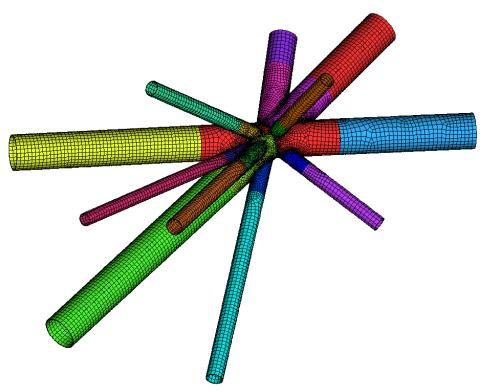
transverse gap between braces. However where the
configuration of brace forces is such that the
ovalisation is greatest, the capacity predicted by the   Overlapped brace cases where ovalisation is
α factor has been shown to be conservative.              restrained are represented by the CIDECT K
Therefore when applying the α factor in capacity         formulae and the AWS with an alpha factor of 1.0.
calculations all brace forces are assumed to act to      The CIDECT K capacity is dependent on the gap
create the maximum ovalisation effects. This was         “g”, with a larger gap approaching the Y load
inline with the design philosophy to envelope            failure mechanism, see Figure 5. A gap of zero is
loads.                                                   outside of the validity limits for the K capacity
                                                         equation. A minimum gap of 20mm was selected
In addition to mutiplanar effects, with more braces      for the overlapped brace check, which is consistent
the connections became more congested, with              with the AWS α=1 capacity. Overlapping truss
overlaps between multiple braces. CIDECT                 chords tended to exhibit much larger gaps, but only
provides guidance for overlap connections but only       a modest reduction in capacity.
when the load is a balanced K load. Careful thought
was required to consider the load path through the
connection for both balanced and unbalanced loads.

The checks carried out followed the AWS and API                          600

provisions for overlapped connections, in particular
                                                         Capacity (kN)
partial footprint net section checks and checks for                      400

load transfer through the common weld between
the braces (further described in Marshall [10]).                         200

Using this philosophy, the load was followed                              0
                                                                               0              20   40              60   80   100

through multiple overlaps. That is when checking                                   CIDECT K
                                                                                                        Gap (mm)

                                                                                   CIDECT Y
the overlapped brace onto the chord, the force from                                AWS K

the overlapping brace is also considered when
                                                         Figure 8: Comparison of CIDECT K, Y
looking at the net force on the chord. (Figure 4)        with AWS K

Checks were also carried out to ensure that the
overlapped brace could withstand the force from          4.3 GROUP 3 – CONGESTED NODES
the overlapping brace (ie acting like a chord for the
overlapping brace). In this check the supporting         The highly congested nature of this group of nodes
brace is stabilized by supporting chord so that          meant that the reading across of the capacities from
ovalisation or general collapse is restrained,           the equations that assume a simple geometry to the
however careful consideration of local plastic and       complex connections was not possible. Therefore
material failure is required. This check was             finite element models of each connection in this
developed using the AWS with correlation back to         group was developed and used to estimate the
the CIDECT formulas. In some cases, a thickened          ultimate capacity.
section at the end of the overlapped brace was
required.                                                FEA models are used by the design codes such as
                                                         CIDECT to determine the ultimate capacities of
                                                         connections and expand on the capacity formulas.
     Nj                                     Ni           The detail of the modelling required to give an
                                                         equivalent capacity to the formulas is significant.
                                                         Failure is taken as a deformation of 3% of the
                                                         diameter, requiring very large plastic strains to be
                                                         captured and a highly nonlinear response.
                                                         Modelling with multiple solid elements through
                                                         thickness would therefore be necessary. This level
                                                         of detail was not considered practical considering
   Check J brace as       Check chord for
   a chord to I brace     combination of Nj + Ni         the number of connections in the group and the
   for Ni                 proportioned to                design time. To simplify the modelling, eight
                          connection and overlap         noded inelastic thin shell elements were used to
                          geometry                       model the connection. Comparison between the
                                                         approach used and the design formulas found that
Figure 7:Additional local failure mechanisms             the shell modelling gave a conservative estimate of
checked in unbalanced load through overlapped            the capacity. In addition the thickness of members
connection.                                              could be changed with only minor modifications to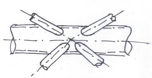
the models. An example of a model generated to         Through thickness shear yielding of a material is
for a node is shown in Figure 9                        not captured by the shell elements used in the
                                                       analysis. Hand checks were used to ensure that the
                                                       punching stresses were not significant and the shell
                                                       bending + membrane response was dominant.

                                                       This group of complex connections were
                                                       approximately 10% of the total number of
                                                       connection for the roof but required 45% of the
                                                       man effort to analyse and design. This
                                                       demonstrates the overheads required to undertake
                                                       detail analysis and the relative simplicity of the
                                                       capacity formulas.

                                                       5 CONCLUSIONS
                                                       This paper presents the design methodology used
Figure 9:Finite element model of a congested node      for the Singapore Sports Hub National Stadium
                                                       CHS connections, balancing against high level
The sub models for the connections require a           technical and practical design requirements of
consistent set of loads to be applied. The enveloped   profile cut connections to provide an effective
forces typically used for connection design could      design within the time and constraints of the project
not be applied and the consistent results from the
global model were used. The 1500 load cases for        A profile cut welded CHS with a thickened can was
the roof were reduced to about 15 load cases for       selected as the connection form for the structure,
each connection. The methodology for the               satisfying weight, strength, fatigue, fabrication and
reduction of load cases considered the critical        architectural requirements.
actions for CHS connection from the CIDECT and
AWS design guides.                                     The 2500 connections were split into 3 groups,
                                                       each utilising the most efficient design methods for
Strain limits were used to define the acceptance       the loading, number of connections and
criteria for the analysed connections. Considering     complexity. These methods were based on existing
the simplified analysis approach used, more            design guides such as CICECT and AWS, plus
conservative strain limits than the 5% strain limit    detailed FEA methods
suggested by Eurocode 1993-1-5, with reductions
based on material thickness and compressive or
tensile response were applied. Table 2 gives strain
limits appropriate for TxT finite element meshing.
Tensile limits are consistent with a CTOD of
0.25mm in the weld toe HAZ, using the
methodology of reference [12].

Table 2: Strain Limit acceptance criteria

  Thickness         For tension          Local
    (mm)             fracture         compression
                                         limit
   t =< 16              5%                4%           Figure 10:Clean line profile connections holding
 16< t =< 20            4%                4%           together the elegant light weight framing the roof.
 20< t =< 40            3%                4%
    40 < t              2%                4%

Geometric nonlinearity was included in the
analysis, therefore effects such as local buckling
were captured in the analysis. When localized shell
buckling is not captured in the analysis, lower
strain limits have been suggested [13].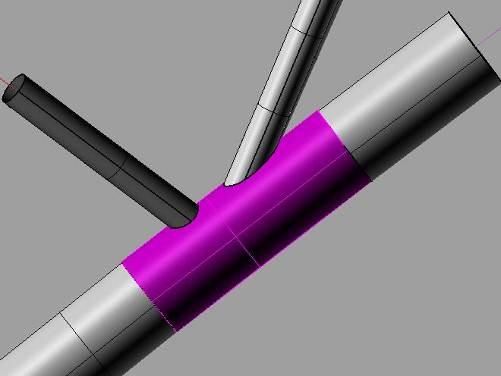
[8] API, 2007: Recommended practice for
ACKNOWLEDGEMENT                                                 planning, designing and constructing offshore
We would like to thank the help and support from                platforms- working stress design. API RP 2A,
the National University of Singapore during                     21st Edition. Suppl. 3, American Petroleum
development of the design philosophy used. Plus                 Institute….
acknowledge the work done by Yongnam to                     [9] AWS D1.1, Structural welding code – Steel,
fabricate and erect the inspiring roof structure.               2010
                                                            [10] Marshall P. W., Design of Welded Tubular
REFERENCES                                                      Connections: Basis and Use of AWS Code
[1] King M, National Stadium Roof Structure –                   Provisions, Elsevier Science Publishers, 1992.
    Singapore Sports Hub, 10th International                [11] Lee MMK, and Wilmshurst, Strength of
    conference on advances in steel concrete                    Multiplaner      Tubular     KK-Joint     under
    composite and hybrid structures Singapore                   antisymmetrical axial loading, ASCE Journal
    July 2012                                                   of Structural Engineering, June 1997.
[2] CIDECT Design Guide 7, For Fabrication,                 [12] van den Brink JH and ter Avest FJ,
    assembly and erection of hollow section                     Assessment of the fracture toughness property
    structures, 1998.                                           of materials in welded tubular joints, SIMS-87,
[3] Qian X, Marshall PW, et al, PJP+ welds for                  Steel in Marine Structures, Elsevier
    tubular structures, Proc IIW Intl Conf,                     Amsterdam.
    Singapore, July 2009.                                   [13] Srirengen K and Marshall PW, Improved
[4] Marshall P, Qian X, et al, Welder-optimized                 Marshall strut element to predict the ultimate
    CJP-equivalency       welds    for     tubular              strength of braced tubular steel offshore
    connections, IIW Welding in the World,                      structures, Proc IMPLAST-2000, Melbourne.
    published online May 2013, Springer
[5] CIDECT Design Guide 1, For CHS joints
    under predominantly static loads, Second
    edition 2008.
[6] BS5950-1, Structural use of steelwork in
    building, 2000.
[7] Eurocode 3: Part 1-8, Connections, 2005.

Figure 11: Progress on site at the end of 2013. Project due for completion in mid-2014
You can also read