Emitting long-distance spiral airborne sound using low-profile planar acoustic antenna - Nature
←
→
Page content transcription
If your browser does not render page correctly, please read the page content below
ARTICLE
                  https://doi.org/10.1038/s41467-021-22325-7                 OPEN

                  Emitting long-distance spiral airborne sound using
                  low-profile planar acoustic antenna
                  Shuxiang Gao           1,   Yunbo Li      2,   Chengrong Ma            1,   Ying Cheng        1✉   & Xiaojun Liu           1✉

                  Recent years have witnessed a rapidly growing interest in exploring the use of spiral sound
                  carrying artificial orbital angular momentum (OAM), toward establishing a spiral-wave-based
1234567890():,;

                  technology that is significantly more efficient in energy or information delivering than
                  the ordinary plane wave technology. A major bottleneck of advancing this technology is the
                  efficient excitation of far-field spiral waves in free space, which is a must in exploring the
                  use of spiral waves for long-distance information transmission and particle manipulation.
                  Here, we report a low-profile planar acoustic antenna to modulate wavefronts emitted from a
                  near-field point source and achieve far-field spiral airborne sound carrying OAM. Using the
                  holographic interferogram as a 2D modulated artificial acoustic impedance metasurface, we
                  show the efficient conversion from the surface wave into the propagating spiral shape beam
                  both numerically and experimentally. The vortex fields with spiral phases originate from the
                  complex inter-modal interactions between cylindrical surface waves and a spatially-
                  modulated impedance boundary condition. This antenna can open new routes to highly
                  integrated spiral sound emitters that are critical for practical acoustic functional devices.

                  1 KeyLaboratory of Modern Acoustics, Department of Physics and Collaborative Innovation Center of Advanced Microstructures, Nanjing University,
                  Nanjing, China. 2 State Key Laboratory of Millimeter Waves, Southeast University, Nanjing, China. ✉email: chengying@nju.edu.cn; liuxiaojun@nju.edu.cn

                  NATURE COMMUNICATIONS | (2021)12:2006 | https://doi.org/10.1038/s41467-021-22325-7 | www.nature.com/naturecommunications                                1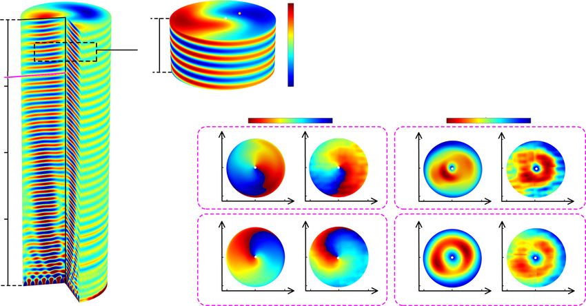
ARTICLE NATURE COMMUNICATIONS | https://doi.org/10.1038/s41467-021-22325-7
T
he introduction of artificial orbital angular momentum Acoustic spiral field
(OAM) has opened up new ways to control classic waves,
which attract a rapidly growing interest in recent years with OAM
toward establishing a spiral-wave-based technology that is sig-
nificantly more energy or information efficient than the ordinary
plane wave technology. Spiral wave field carrying OAM presents a
helicoid phase dependence containing a screw-type phase sin-
gularity at the center, leading to the null pressure amplitude at the
beam axis. At the same time, the helical phase wavefront can exert
a measurable torque on the absorptive object1–6. These repre-
sentative characteristics of the vortices can be useful for manip-
ulating particles such as trapping7–10, pulling11–14, levitation15,16, z
or data transmission17–20 in both optics and acoustics. The
inherent polarization of electromagnetic (optical) waves limits the
efficiency of generated spiral field, making the spiral field more Sound source
promising in acoustics. There have been substantial efforts to
transpose the idea of helical wave from optics to acoustics.
Among them, the pioneering design of synthesizing experimen-
tally acoustical vortices with four synchronized transducers was
first proposed by Marston et al.21 and prominent efforts have
been dedicated to developing relevant theories in this field22,23 Surface wave
along with this seminal work. The conventional methods for
generating acoustic OAM can be divided into two major cate- Metasurface
gories: active and passive. Breakthroughs have been first made
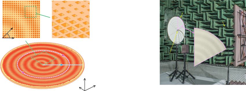
based on the active technology essentially using acoustic phased- Fig. 1 Illustration of the metasurface antennas. The axisymmetric acoustic
array technology24–26, resorting to a large number of individually surface waves are launched by a monopolar sound source (yellow
addressed transducers with corresponding signal processing sys- pentagram) located at the center of the metasurface antennas (orange
tem, whereas the pioneering passive methods employ transmis- plate), as illustrated by the purple wave packet representing the pressure
sive architecture, which is in need of either a bulky planar field amplitude. These surface waves carrying zero OAM are scattered into
emitting transducer or large spatially-varying thickness27,28 based the desired far-field wave beam with artificial OAM, depicted by the vortex
on the acoustic diffraction effects. phase fronts.
On the other hand, the emergence of ultra-thin acoustic arti-
ficial structure, which is called metasurface, provides new ideas interdigitated transducer were used to encode the phase of the
for implementing acoustic vortex. Compared with the traditional field like a hologram and shape SAWs instead of the metasurface
three-dimensional (3D) acoustic meta-material, two-dimensional proposed here.
(2D) metasurface has the advantages of low profile, small loss,
and extreme control of phased-array wave field, and thus can Results
effectively carry out the acoustic wavefront regulation29–37 and Theory of impedance metasurface. The concept of SAW impe-
microparticle manipulation20,38. Recently, a new mechanism of dance is first put forward to play a key role as a bridge linking
passive generated OAM is produced by employing the acoustic propagating waves and evanescent surface waves. According to
resonance, which is independent of thickness and effective pro- the theory of holography45, the phase information of the holo-
pagating wavelengths39. It is expected that for applications such graphy could be captured by interfering the scattered (radiation)
as fluid mixing, operation in the near field of this antenna can be wave from an object with a reference wave of the same frequency.
useful. Although the requirements for miniaturization are met, For a reference wave ψref and an object wave ψobj, the holographic
the propagating distance in free-space airborne environment is
still limited, about 2 wavelengths. To extend the sound energy to interferogram is given by Ψ ¼ ψ ref þ ψ obj . In our approach,
46
the far field, the sound wave needs to be transmitted in a acoustic impedance is introduced to characterize the intensity
waveguide40, which is difficult to apply in practice. Otherwise, the gradient of the interferogram; thus, it can be rewritten as
entire system has to be embedded in fluid41–43, suffering from the
extreme impedance mismatch. Therefore, novel schemes are in Z ¼ j½X þ M Re ðψ ref ψ obj Þ; ð1Þ
great need to develop integrated functional devices for long-
distance propagation of spiral sound in free space that can where X and M are the average SAW impedance and modulating
overcome the limitations of current acoustic technologies. depth, respectively. When the interference pattern is excited by
In this work, we report the discovery of an approach for the the reference wave, the desired object wave can be reproduced as
2
excitation of far-field spiral wave in free space by modulating the ψ ref ðψ ref ψ obj Þ ¼ ψ ref ψ obj .
evanescent spoof surface acoustic wave (SAW). A low-profile To facilitate the implementation, the ideal continuous holo-
planar acoustic antenna based on holographic impedance meta- graphic impedance metasurface should be discretized into the
surface is constructed. As shown in Fig. 1, when the SAW field is discrete metasurface consisting of 2D modulated basic unit cells.
radiated by an ordinary point-like sound source at the center, the Each cell as shown in Fig. 2a can be recognized as a rigid body
structure can effectively regulate the phase delay of SAW to with a subwavelength center-hollow-hole filled with background
generate specific spatial wavefront pattern with the output phase medium air47–50, which is designed to couple the SAW modes
at the exit end spirally distributed along the θ direction, whereby with surrounding medium. By gradually changing the hole sizes,
far-field acoustic spiral waves can be formed. It is noteworthy that we can obtain the different surface refractive indexes and SAW
synthesizing bulk acoustical vortices in near-field through Ray- impedances without breaking the quasi-periodicity of the whole
leigh SAWs generated by spiraling holograms was previously structure. In this study, the eigen-mode analysis method in
proposed in ref. 44, in which active holograms based on spiraling COMSOL Multiphysics is applied to extract the dispersive
2 NATURE COMMUNICATIONS | (2021)12:2006 | https://doi.org/10.1038/s41467-021-22325-7 | www.nature.com/naturecommunications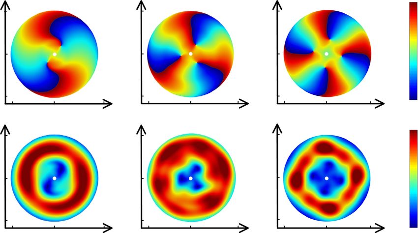
NATURE COMMUNICATIONS | https://doi.org/10.1038/s41467-021-22325-7 ARTICLE
a b c
PML 12
1.4 400
Frequency (kHz)
Im(Zs) (Pa·s/m)
8 1.3 300
a = 1.0 mm
6 a = 1.8 mm
n
Air 1.2
Hard a = 2.6 mm 200
4 a = 3.4 mm
border 1.1
a a = 4.2 mm
a = 5.0 mm 100
h In the air 1.0
z 0 0
y d 0 10 20 30 40 50 60 70 80 90 1 2 3 4 5
x Hole size (mm)
Phase (degree)
Fig. 2 Building block used for artificial phase modulations. a Basic unit cell: cuboid holes embedded in a solid base are arranged in square lattice, with the
period of d = 6 mm, the hole depth of h = 9 mm, and the variable hole size a. b Dispersion curves of unit cells with different hole sizes a, while the black line
with triangle marks denotes the air line. c Surface refractive index (pink) and surface impedance (blue) curves with changing hole sizes at 6000 Hz.
relation between the phase delay of a unit cell (with a fixed period represented by
of d) and the frequency (Fig. 2b), which is defined as 2πm0
p¼ ; ð7Þ
ϕ ¼ kt d ¼ k0 nd; ð2Þ k0 n k0 sin θ0
where ϕ corresponds to the phase difference across the unit cell, which can be rewritten as
kt and k0 are the wave numbers on the metasurface and in free 2πm0
k0 sin θ0 ¼ k0 n : ð8Þ
space, respectively, and n is the average surface refractive index of p
the metasurface. Based on Eq. (2), the effective surface refractive
index can be directly acquired. Combining with the equation of Here the left side of Eq. (8) represents the radiation term,
SAW impedance (Supplementary Note 1), the relation between whereas the first and second term of the right side are the wave
the phase offset and SAW impedance can be described as: vector of SAW and the modulation term, respectively. In essence,
sffiffiffiffiffiffiffiffiffiffiffiffiffiffiffiffiffiffiffiffiffiffiffiffi the shift of wave vector transfers the surface wave to the radiation
pffiffiffiffiffiffiffiffiffiffiffiffiffi 2 wave (Supplementary Note 2). It is noteworthy that what we need
ϕ ð3Þ
Zs ¼ Z0 1 n ¼ Z0 1
2 : is the −1 order diffraction term only, that is to say, when m0 = 1,
k0 d the left side of the equation should be modulated into the
radiation area (i.e., point I to II); but when m0 = 2, this term need
Therefore, once the phase offset is acquired through the
to be removed out of the air cone (i.e., point I to III).
dispersion curve, the effective surface refractive index and SAW
impedance can be calculated correspondingly (Fig. 2c). On the
contrary, the hole size can be set using interpolation method, as Acoustic spiral field. In a spiral field, the wave will twist along its
specific hole size corresponds to a particular phase delay at a axis as it travels, forming a beam shape similar to a bottle screw.
certain frequency, provided the phase delay is set by the The propagation phase satisfies:
determined impedance. For illustration, at the intended working ϕobj ðθÞ ¼ ejmθ ; ð9Þ
frequency of 6000 Hz, the height of the hole is 9 mm, which can
be regarded as subwavelength, and the hole size varies from 2 to in which the expression about the exit direction is set to be 0
4 mm with the values of X and M determined as 170.9 and 99.8, (sin 0 ) as the desired direction of radiation is along the normal of
respectively. the metasurface, whereas mθ acts as an additional phase
To complete the design of a 2D modulated artificial acoustic depending on the azimuth angle, to generate a twisted wavefront.
metasurface, the SAW impedance textures of the surface should On the basis of the previous derivation, the SAW impedance
be first shaped. Assuming that a cylindrical sound source is interferogram here is given by
located at the origin on the metasurface, which occupies the X–Y Z s ¼ j½X þ M cosðk0 nr mθÞ; ð10Þ
plane, the reference wave (or the surface plane wave) can be
written as where m is called the topological charge or the order of the spiral
field, which is defined as the number of twist of the wavefront
ψ ref ¼ ejk0 nr ; ð4Þ within one wavelength distance. For generating a first-order
vortex beam with m = 1, the holographic pattern is shown in
where r is the radial distance from the center origin. The object
Fig. 3a, which is combined with the dispersion and impedance
wave is defined as51
data shown in Fig. 2b, c, to determine the required hole as a
ψ obj ¼ ejk0 r sin θ0 ; ð5Þ function of spatial position. The pattern is a spiral-shaped strip
and the spiral direction of the outgoing beam is consistent with
where θ0 is the desired radiation elevation angle. Hence, the the rotation of the surface spiral impedance strip.
hologram composed of impedance can be expressed as We construct a sample antenna of finite dimension, whose
profile of hole size a in the circumference and radial directions
Z s ¼ j½X þ M Re ðψ ref ψ obj Þ along pink dashed circle and blue dashed hatching line labeled in
ð6Þ
¼ j½X þ M cosðk0 nr k0 r sin θ0 Þ: Fig. 3a are shown in Fig. 3b, c, respectively. The whole sample is a
round sheet with a radius of 30 cm, composed of 7660 unit cells.
To obtain the periodicity of the holographic distribution of Smaller transverse dimensions and the limitations are discussed
surface impedance along one direction, we make the phase item in Supplementary Note 3. Measurements are designed and carried
satisfy ðk0 n k0 sin θ0 Þp ¼ 2πm0 , so the corresponding period is out to validate the generation of far-field spiral waves by the
NATURE COMMUNICATIONS | (2021)12:2006 | https://doi.org/10.1038/s41467-021-22325-7 | www.nature.com/naturecommunications 3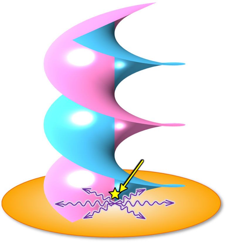
ARTICLE                                                                                        NATURE COMMUNICATIONS | https://doi.org/10.1038/s41467-021-22325-7

    a                                                              b                                                        d
                                                                                     4.0

                                                                    Hole size (mm)
                                                                                     3.5                                             Metasurface
     y
                                                                                     3.0                                                           Microphone
         x
                  r                                                                  2.5
                                                                                                         r = 0.18 m
                                                                                     2.0
              θ
         O                                                                                 0     90      180    270   360
                                                                   c                              Azimuth (°)
                                                                                                                θ = 320°

                                                                   Hole size (mm)
                                                                                     4.0
                                                                                                                                Sound source
                                                                                     3.5
                                                                                     3.0
                                                                                     2.5
                                                           z                         2.0
                                                      y        x                        0.0        0.1         0.2    0.3
                                                                                               Radial distance (m)

Fig. 3 Planar acoustic antenna design. a Schematic diagram. The structure details in the green dashed squares are shown in expanded schematic form
(square insets). b, c Plot of the geometric parameters that are implemented. The pink solid (blue solid) curve illustrates the profile of hole size a along the
pink dashed circle (blue dashed hatching line) in the circumference (radial) direction. d Experimental setup. The fanshaped inset shows partial
enlarged view.

proposed method in the anechoic chamber and the photograph of                                         Fig. 4b, a section of the far-field region is enlarged to manifest the
experimental setup is illustrated in Fig. 3d. In fabrication, the                                     distortion of both amplitude and phase more clearly (see
sample material is chosen to be photosensitive resin (via the 3D                                      Supplementary Movie 1 for the dynamic view of acoustic vortex
printing technology), which can be treated as acoustically rigid for                                  beam). From the cross-sectional view, the phases have shifted
airborne sound. In measurements, we employed a point-like                                             from −π to π in each turn, revealing the expected topological
source placed at a quarter wavelength away from the metasurface                                       charge m = 1. Moreover, the superposition of the phases at
to excite the SAW, whose directivity is similar to that of an                                         the center results in an intensity minimum at z axis (point B),
electromagnetic dipole in accordance with mirror image princi-                                        which can be also seen in Fig. 4c. By contrast, sound energy is
ple. The far-field radiation information is detected by microphone                                     well concentrated in other areas of circular wavefront (i.e., point
array (G.R.A.S. Type 40PH), moving step by step in the plane                                          A) so that the beam can reach the far field, even though for each
parallel to the metasurface, with one additional microphone fixed                                      wavelength the wavefront of the vortex propagates forward, the
in the outgoing field as a reference signal. As a result, the                                          sound pressure amplitude will decrease by around 4% as a result
amplitude and phase of the sound in each scan point can be                                            of the inevitable viscous loss in experiments. In addition, the
recorded in real time.                                                                                measured phase distributions and sound amplitudes at the far-
   The corresponding simulation results are shown in Fig. 4 and                                       field cross-sections z = 1.57 and 2.00 m are shown in Fig. 4d (see
the right-handed radiation wave can be received in the z                                              Supplementary Note 4 for measured evolution process of phase
direction. The simulation is carried out in a cylindrical calculation                                 diagrams within one period). The expected OAM in a first-order
domain with the designed metasurface positioned at the bottom                                         spiral beam with a smooth helical phase and null amplitude at the
of the domain and the spatial lateral extent of the simulation                                        core can be clearly observed. Measurement results have good
window is selected to be 0.34 m, which is about 0.7λ beyond the                                       agreements with the numerical simulations, which demonstrates
radius of the metasurface. The cylindrical wave radiation                                             the performance of metasurface antenna in converting acoustic
condition is applied on the exteriors of the domain to prevent                                        surface wave to a radiation beam with OAM. The weak
boundary diffraction at the edges, whereas a perfect matching                                         asymmetry in the amplitude originates from the discretization
layer is employed to absorb the radiated sound waves in the far                                       differences among the impedances in each direction, which leads
field. Figure 4a illustrates a cutaway view of the outgoing sound                                      to the spiral stripes in impedance, despite the superficial
field with the same radius of the metasurface. Good collimation                                        resemblances of cylindrical symmetry. Consequently, the impe-
characteristics can be observed along the entire propagation axis,                                    dances traversed by the surface waves on each path are not
making it possible to form a stable acoustic vortex beam over a                                       identical to bring the corresponding outgoing wave field with an
considerably long distance. For illustration, we only depicted the                                    azimuthal angular dependence of e−jmθ, which introduces some
spiral sound field within 2.00 m, which has reached 35 spatial                                         unevenness in the output amplitude.
wavelengths already. Given that the near field is inevitably subject                                      From the above discussions, we can see that the proposed
to the interference of surface wave, the critical distance between                                    method achieves the desired first-order vortex beam both
the near- and far-field is defined as z = R2/λ = 1.57 m referring to                                    theoretically and experimentally. This method can be further
the radiation of a circular piston52, and the far field exhibits the                                   extended to higher-order vortex beams by directly assigning a
perfect acoustic vortex. The sound energy of the vortex is                                            larger value to m. Figure 5 presents the amplitude and phase
obtained by integrating the intensity Iz of the horizontal section of                                 distributions of wavefront of the far-field vortex beam with
the cylindrical calculation domain in the far-field and its ratio to                                   topological charges m = 2–4 (see Supplementary Movie 2 for
the total energy radiated from sound source obtained by                                               corresponding dynamic view). As in the previous section, the
integrating the sound intensity over the entire boundary of the                                       cross-sections at 2 m confirm that the long-distance propagation
model determines the efficiency of energy conversion as 76%. In                                        of the spiral beam could be maintained via adding the number of

4                     NATURE COMMUNICATIONS | (2021)12:2006 | https://doi.org/10.1038/s41467-021-22325-7 | www.nature.com/naturecommunications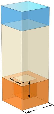
NATURE COMMUNICATIONS | https://doi.org/10.1038/s41467-021-22325-7 ARTICLE
a b c
1.0
Sound pressure
1
R A Point A
(Normalized)
2.0 1.85
Sound field
B 0.5 Exp.
Point B
0.0 Exp.
l Point A
-0.5 Sim.
r 1.65
Point B
Sim.
1.57 -1.0
1.5 -1
z(m) 1.65 1.70 1.75 1.80 1.85
y x Distance (m)
Phase Amplitude
d π -π 1 0
0.3 Sim. Exp. 0.3 Sim. Exp.
1.0
y(m)
z = 1.57 m
(28λ)
-0.3 -0.3
0.5
0.3 Sim. Exp. 0.3 Sim. Exp.
z = 2.00 m
y(m)
(35λ)
0 -0.3 -0.3
-0.3 0.3 -0.3 0.3 -0 .3 0.3 -0.3 0.3
x(m) x(m)
Fig. 4 Far-field spiral sound in free space. a Normalized sound pressure field along the propagation axis in cutaway view. The cutting position is the
cylinder with the radius R = 0.3 m. The transition point between the near and far field is around 1.57 m. b Zoom-in of the far-field rotating wavefront, which
is taken from a region with radius r = 0.2 m and l = 0.2 m, located at z0 = 1.65 m (black dashed line in a). c Experimentally measured (Exp.) and simulated
(Sim.) sound pressure profiles along the vertical lines across point A and B in b. d Experimentally measured and simulated phase and amplitude distribution
of the helical wavefront at two observation planes located at 1.57 and 2.00 m away from the metasurface, respectively. The white dots refer to the
geometric centers of the phase cross-sections.
a m=2 b m=3 c m=4
π
0.3
Phase
y(m)
-0.3 -π
1
0.3
Amplitude
y(m)
-0.3 0
-0.3 0.3 -0.3 0.3 -0.3 0.3
x(m) x(m) x(m)
Fig. 5 High-order far-field vortex beams. a–c Show the vortex beams with OAM topological charges m = 2–4. Top and bottom row show the phase and
amplitude distribution of the pressure field, respectively.
turns. It is noteworthy that we concentrate on the modulation of rotation with the azimuth angle is increased, where the helical
the output phase in this work. Although the radial distribution of wavefront reaches a total phase shift of 2πm over a complete turn.
the amplitude in theoretical design is set to be uniform, the actual Hence, the phase singularity still emerges at the core without
amplitude values on each path are not exactly identical due to the offset, while the hollow part of the central area is extended arising
impedance modulation and the quite modest difference can be from the variation of the phase, indicating that the vortex of
evaluated from the stable vortex beams in far-fields in simulations charge −m has been split into m vortices of charge −1 rather
and experiments. In addition, in the case of m > 1, the phase than 1. This phenomenon can be ascribed to effect that the high-
NATURE COMMUNICATIONS | (2021)12:2006 | https://doi.org/10.1038/s41467-021-22325-7 | www.nature.com/naturecommunications 5ARTICLE NATURE COMMUNICATIONS | https://doi.org/10.1038/s41467-021-22325-7
order vortex has a more unstable structure than the first-order 4. Li, W. et al. Rotational manipulation by acoustic radiation torque of high-
vortex and some slight disturbances could degenerate the order vortex beams generated by an artificial structured plate. Appl. Phys. Lett.
unstable high-order vortex into multiple stable first-order 113, 051902 (2018).
5. Anhäuser, A., Wunenburger, R. & Brasselet, E. Acoustic rotational
vortices53,54. In our simulations, the disturbances mainly arise manipulation using orbital angular momentum transfer. Phys. Rev. Lett. 109,
from the weak non-cylindrically symmetric structure design and 034301 (2012).
the interference of the point-like sound source with the radiated 6. Zhang, L. et al. Reversals of orbital angular momentum transfer and radiation
acoustic vortex54,55. torque. Phys. Rev. Appl. 10, 034039 (2018).
7. Marzo, A., Caleap, M. & Drinkwater, B. W. Acoustic virtual vortices with
tunable orbital angular momentum for trapping of mie particles. Phys. Rev.
Discussion Lett. 120, 044301 (2018).
Derived from its extraordinary properties of effective surface 8. Baresch, D., Thomas, J.-L. & Marchiano, R. Orbital angular momentum
impedance, the planarized vortex antenna exhibits high efficiency transfer to stably trapped elastic particles in acoustical vortex beams. Phys.
in the modulation and transformation of evanescent waves into Rev. Lett. 121, 074301 (2018).
9. Hong, Z. Y., Zhang, J. & Drinkwater, B. W. Observation of orbital angular
complex far-field radiated sound waves, which may promise momentum transfer from bessel-shaped acoustic vortices to diphasic liquid-
extensive and significant application advantages. Although we microparticle mixtures. Phys. Rev. Lett. 114, 214301 (2015).
mainly focused on the generation of long-distance spiral beam in 10. Baudoin, M. et al. Folding a focalized acoustical vortex on a flat holographic
this work, the proposed strategy also offers a feasible approach to transducer: miniaturized selective acoustical tweezers. Sci. Adv. 5, eaav1967
design an integrated and small-sized system-level antenna for (2019).
11. Pfeiffer, C. & Grbic, A. Generating stable tractor beams with dielectric
realizing versatile functions with superior performance far metasurfaces. Phys. Rev. B 91, 115408 (2015).
beyond the scope of this work, as well as being loaded on other 12. Xu, S., Qiu, C. & Liu, Z. Transversally stable acoustic pulling force produced
conformal functional devices of irregular shapes. For example, the by two crossed plane waves. Europhys. Lett. 99, 44003 (2012).
ability of far-field collimated vortex propagation with stable 13. Xia, X. et al. Acoustically driven particle delivery assisted by a graded grating
topological charge can be used in non-contact manipulation of plate. Appl. Phys. Lett. 111, 031903 (2017).
14. Zhang, P. et al. Generation of acoustic self-bending and bottle beams by phase
particles and acoustic long-distance communication. Moreover, engineering. Nat. Commun. 5, 4316 (2014).
our design scheme of holographic impedance metasurface can 15. Hong, Z. Y. et al. Dynamics of levitated objects in acoustic vortex fields. Sci.
also be extended to acoustic multi-mode communications as a Rep. 7, 7093 (2017).
consequence of the flexible construction of surface impedances 16. Memoli, G. et al. Metamaterial bricks and quantization of meta-surfaces. Nat.
and integration of different modes such as various angular Commun. 8, 14608 (2017).
17. Li, Z. et al. Tripling the capacity of optical vortices by nonlinear metasurface.
momentums, working frequencies, and outgoing beam angles, Laser Photonics Rev. 12, 1800164 (2018).
which have promising application prospects in the field of signal 18. Shi, C., Dubois, M., Wang, Y. & Zhang, X. High-speed acoustic
multiplexing (e.g., see Supplementary Figs. 6 and 7 for illustration communication by multiplexing orbital angular momentum. Proc. Natl. Acad.
of dual-frequency and dual-angle OAM-dependent acoustic Sci. USA 114, 7250–7253 (2017).
antenna, respectively; detailed discussion can be found in Sup- 19. Marzo, A. et al. Holographic acoustic elements for manipulation of levitated
objects. Nat. Commun. 6, 8661 (2015).
plementary Note 5). 20. Li, Y., Qiu, C., Xu, S., Ke, M. & Liu, Z. Theoretical study of large-angle
In summary, we report an approach to building a holographic bending transport of microparticles by 2d acoustic half-bessel beams. Sci. Rep.
impedance metasurface that can associate acoustic surface waves 5, 13063 (2015).
with spatial waves and realize far-field radiation beams carrying 21. Hefner, B. T. & Marston, P. L. An acoustical helicoidal wave transducer with
OAM. The underlying physics of wavefront control and the stable applications for the alignment of ultrasonic and underwater systems. J. Acoust.
Soc. Am. 106, 3313–3316 (1999).
topological charge is demonstrated in a considerably long dis- 22. Marston, P. L. Axial radiation force of a bessel beam on a sphere and direction
tance in the propagation direction, through both simulations and reversal of the force. J. Acoust. Soc. Am. 120, 3518–3524 (2006).
experiments. With the compact profile, long propagation dis- 23. Marston, P. L. Scattering of a bessel beam by a sphere: Ii. helicoidal case and
tance, controllable stable topological charge, and easy-to-manu- spherical shell example. J. Acoust. Soc. Am. 124, 2905–2910 (2008).
facture, the intriguing metasurface antenna stands in contrast to 24. Thomas, J.-L. & Marchiano, R. Pseudo angular momentum and topological
charge conservation for nonlinear acoustical vortices. Phys. Rev. Lett. 91,
previous transmissive designs, which may have many potential 244302 (2003).
applications in future integrated functional devices. 25. Muelas-Hurtado, R. D., Ealo, J. L., Pazos-Ospina, J. F. & Volke-Sepúlveda, K.
Acoustic analysis of a broadband spiral source for the simultaneous generation
Data availability of multiple bessel vortices in air. J. Acoust. Soc. Am. 144, 3252–3261 (2018).
The data that support the findings of this study are available from the corresponding 26. Riaud, A. et al. Anisotropic swirling surface acoustic waves from inverse
authors on reasonable request. filtering for on-chip generation of acoustic vortices. Phys. Rev. Appl. 4, 034004
(2015).
27. Ealo, J. L., Prieto, J. C. & Seco Granja, F. Airborne ultrasonic vortex generation
Code availability using flexible ferroelectrets. IEEE Trans. Sonics Ultrason. 58, 1651–1657
The code used to calculate the results for this work is available from the corresponding (2011).
author upon reasonable request. 28. Wunenburger, R., Lozano, J. I. V. & Brasselet, E. Acoustic orbital angular
momentum transfer to matter by chiral scattering. New J. Phys. 17, 103022
(2015).
Received: 21 May 2019; Accepted: 11 March 2021; 29. Tang, K. et al. Anomalous refraction of airborne sound through ultrathin
metasurfaces. Sci. Rep. 4, 6517 (2014).
30. Mei, J. & Wu, Y. Controllable transmission and total reflection through an
impedance-matched acoustic metasurface. J. Appl. Phys. 16, 123007 (2014).
31. Naify, C. J. et al. Generation of topologically diverse acoustic vortex beams
using a compact metamaterial aperture. Appl. Phys. Lett. 108, 223503 (2016).
References 32. Jia, Y.-R., Ji, W.-Q., Wu, D.-J. & Liu, X.-J. Metasurface-enabled airborne
1. Xiao, S. et al. Spin-dependent optics with metasurfaces. Nanophotonics 6, fractional acoustic vortex emitter. Appl. Phys. Lett. 113, 173502 (2018).
215–234 (2016). 33. Zhang, Y. et al. Anomalous reflection and vortex beam generation by multi-bit
2. Yue, F. et al. Vector vortex beam generation with a single plasmonic coding acoustic metasurfaces. Appl. Phys. Lett. 114, 091905 (2019).
metasurface. ACS Photonics 3, 1558–1563 (2016). 34. Liang, Z. & Li, J. Extreme acoustic metamaterial by coiling up space. Phys. Rev.
3. Wang, T. et al. Particle manipulation with acoustic vortex beam induced Lett. 108, 114301 (2012).
by a brass plate with spiral shape structure. Appl. Phys. Lett. 109, 123506 35. Cummer, S. A., Christensen, J. & Alù, A. Controlling sound with acoustic
(2016). metamaterials. Nat. Rev. Mater. 1, 16001 (2016).
6 NATURE COMMUNICATIONS | (2021)12:2006 | https://doi.org/10.1038/s41467-021-22325-7 | www.nature.com/naturecommunicationsNATURE COMMUNICATIONS | https://doi.org/10.1038/s41467-021-22325-7 ARTICLE
36. Tian, Y., Wei, Q., Cheng, Y. & Liu, X. Acoustic holography based on 55. Lavery, M. P. J. et al. Free-space propagation of high-dimensional structured
composite metasurface with decoupled modulation of phase and amplitude. optical fields in an urban environment. Sci. Adv 3, e1700552 (2017).
Appl. Phys. Lett. 110, 191901 (2017).
37. Jiang, X., Ta, D. & Wang, W. Modulation of orbital-angular-momentum
symmetry of nondiffractive acoustic vortex beams and realization using a Acknowledgements
metasurface. Phys. Rev. Appl. 14, 034014 (2020). This work was supported by the National Basic Research Program of China
38. Tang, K. et al. Making acoustic half-bessel beams with metasurfaces. Jpn. J. (2017YFA0303702) and NSFC (12074183, 11922407, 11834008, and 11874215).
Appl. Phys. 55, 110302 (2016).
39. Ye, L. et al. Making sound vortices by metasurfaces. AIP Adv. 6, 085007 Author contributions
(2016). Y.C. initiated the project. Y.C. and X.L. guided the research. S.G. and Y.L. conceived the
40. Jiang, X., Li, Y., Liang, B., Cheng, J.-c. & Zhang, L. Convert acoustic design. S.G. and C.M. carried out the theoretical modeling and FEM simulations,
resonances to orbital angular momentum. Phys. Rev. Lett. 117, 034301 (2016). designed the experimental setup, and conducted the measurements. All authors con-
41. Jiménez, N. et al. Formation of high-order acoustic bessel beams by spiral tributed to the data analysis and manuscript writing. S.G. and Y.L. contributed to this
diffraction gratings. Phys. Rev. E 94, 053004 (2016). work equally.
42. Jiménez, N., Romero-García, V., García-Raffi, L. M., Camarena, F. & Staliunas,
K. Sharp acoustic vortex focusing by fresnel-spiral zone plates. Appl. Phys.
Lett. 112, 204101 (2018). Competing interests
43. Jia, Y.-R., Wei, Q., Wu, D.-J., Xu, Z. & Liu, X.-J. Generation of fractional The authors declare no competing interests.
acoustic vortex with a discrete archimedean spiral structure plate. Appl. Phys.
Lett. 112, 173501 (2018).
44. Riaud, A., Baudoin, M., Bou Matar, O., Becerra, L. & Thomas, J.-L. Selective
Additional information
Supplementary information The online version contains supplementary material
manipulation of microscopic particles with precursor swirling rayleigh waves.
available at https://doi.org/10.1038/s41467-021-22325-7.
Phys. Rev. Appl. 7, 024007 (2017).
45. Ramo, S., Whinnery, J. R., Van Duzer, T. Fields and Waves in Communication
Correspondence and requests for materials should be addressed to Y.C. or X.L.
Electronics (Wiley, 2008).
46. Li, Y. B., Wan, X., Cai, B. G., Cheng, Q. & Cui, T. J. Frequency-controls of Peer review information Nature Communications thanks the anonymous reviewer(s) for
electromagnetic multi-beam scanning by metasurfaces. Sci. Rep. 4, 6921 their contribution to the peer review of this work. Peer reviewer reports are available.
(2014).
47. Cheng, Y., Xu, J. Y. & Liu, X. J. Tunable sound directional beaming assisted by Reprints and permission information is available at http://www.nature.com/reprints
acoustic surface wave. Appl. Phys. Lett. 96, 071910 (2010).
48. Christensen, J., Martín-Moreno, L. & Garcia-Vidal, F. J. Enhanced acoustical
Publisher’s note Springer Nature remains neutral with regard to jurisdictional claims in
transmission and beaming effect through a single aperture. Phys. Rev. B 81,
published maps and institutional affiliations.
174104 (2010).
49. Christensen, J., Fernandez-Dominguez, A. I., de Leon-Perez, F., Martin-
Moreno, L. & Garcia-Vidal, F. J. Collimation of sound assisted by acoustic
surface waves. Nat. Phys. 3, 851 (2007). Open Access This article is licensed under a Creative Commons
50. Liu, T., Chen, F., Liang, S., Gao, H. & Zhu, J. Subwavelength sound focusing Attribution 4.0 International License, which permits use, sharing,
and imaging via gradient metasurface-enabled spoof surface acoustic wave adaptation, distribution and reproduction in any medium or format, as long as you give
modulation. Phys. Rev. Appl. 11, 034061 (2019). appropriate credit to the original author(s) and the source, provide a link to the Creative
51. Li, Y. B. et al. Dual-physics manipulation of electromagnetic waves by system- Commons license, and indicate if changes were made. The images or other third party
level design of metasurfaces to reach extreme control of radiation beams. Adv. material in this article are included in the article’s Creative Commons license, unless
Mater. Technol. 2, 1600196 (2017). indicated otherwise in a credit line to the material. If material is not included in the
52. Kinsler, L. E., Frey, A. R., Coppens, A. B., and Sanders, J. V. Fundamentals of article’s Creative Commons license and your intended use is not permitted by statutory
Acoustics (Wiley, 1999). regulation or exceeds the permitted use, you will need to obtain permission directly from
53. Guo, Z. et al. High-order acoustic vortex field generation based on a the copyright holder. To view a copy of this license, visit http://creativecommons.org/
metasurface. Phys. Rev. E 100, 053315 (2019). licenses/by/4.0/.
54. Fan, S.-W. et al. Acoustic vortices with high-order orbital angular
momentum by a continuously tunable metasurface. Appl. Phys. Lett. 116,
163504 (2020). © The Author(s) 2021
NATURE COMMUNICATIONS | (2021)12:2006 | https://doi.org/10.1038/s41467-021-22325-7 | www.nature.com/naturecommunications 7You can also read