Guidance Document for the Design,
Siting and Operation of Earth-Lined
      Slurry/Effluent Stores
←
→
Page content transcription
If your browser does not render page correctly, please read the page content below
Guidance Document for the Design,
Siting and Operation of Earth-Lined
Slurry/Effluent Stores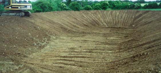
TABLE OF CONTENTS
1     Introduction.........................................................................................................8
    1.1     Introduction............................................................................................................ 8
    1.2     What is an earth-lined slurry/effluent store?................................................. 8
    1.3     ELS role in the storage of animal slurry and effluent ................................. 8
    1.4     Advantages and disadvantages of ELSs ....................................................... 9
    1.5     The need for a guidance document for ELSs................................................ 9
    1.6     Overview of guidance document...................................................................... 9
2     Site characterisation: general overview ....................................................11
    2.1     Introduction.......................................................................................................... 11
    2.2     Objectives of the site assessment ................................................................. 11
    2.3     Risk based approach ......................................................................................... 12
    2.4     Key environmental receptors .......................................................................... 12
    2.5     Hazard characterisation.................................................................................... 12
      2.5.1    General............................................................................................................................ 12
      2.5.2    Typical characteristics of effluent ................................................................................ 13
    2.6     Site suitability (general requirements).......................................................... 14
      2.6.1    Site restrictions............................................................................................................... 14
      2.6.2    Minimum design requirements..................................................................................... 14
3     Undertaking the site assessment................................................................15
    3.1     Introduction.......................................................................................................... 15
    3.2     Approach to site assessment.......................................................................... 15
    3.3     Collation of supporting information .............................................................. 15
      3.3.1    Preliminary consultation................................................................................................ 15
      3.3.2    Collation of relevant environmental data .................................................................... 16
      (i)      General............................................................................................................................ 16
      (ii)     Topography..................................................................................................................... 16
      (iii)    Surface water.................................................................................................................. 16
      (iv)     Geological and hydrogeological................................................................................... 16
      (v)      Flora, fauna and cultural heritage................................................................................ 17
      (vi)     Drainage.......................................................................................................................... 17
      (vii)    Public utilities .................................................................................................................. 17
      (viii)   General planning............................................................................................................ 17
      3.3.3    Interpreting the results of the background information ............................................. 17
    3.4     Visual assessment ............................................................................................. 18
      3.4.1    On-site hazard evaluation............................................................................................. 18
      3.4.2    Visual assessment of receptors................................................................................... 18
      (i)      Topography and landscape fit...................................................................................... 18
      (ii)     Cultural heritage............................................................................................................. 19
      (iii)    Human ............................................................................................................................. 19
      (iv)     Flora and fauna .............................................................................................................. 19
      (v)      Surface water.................................................................................................................. 19
      (vi)     Drainage systems .......................................................................................................... 19
      (vii)    Groundwater ................................................................................................................... 19
      (viii)   Climate............................................................................................................................. 19
      (ix)     Soil and subsoils ............................................................................................................ 19
      3.4.3    Interpreting the results of the visual assessment ...................................................... 20

                                                                                                                                                   2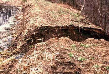
3.5    Trial holes ............................................................................................................. 20
      3.5.1   General............................................................................................................................ 20
      3.5.2   Conducting and logging the trial hole.......................................................................... 20
      3.5.3   Interpreting the findings from the trial hole investigation.......................................... 21
    3.6    Decision process and preparation of recommendations ........................ 21
4     Regulatory procedure.....................................................................................23
    4.1    Introduction.......................................................................................................... 23
    4.2    Relevant legislation............................................................................................ 23
    4.3    Planning pre-consultation................................................................................ 23
    4.4    Planning permission/documentation ............................................................ 23
5     Earth-lined slurry/effluent store design.....................................................24
    5.1    Introduction.......................................................................................................... 24
    5.2    Preparation for the design ............................................................................... 24
    5.3    Volume requirements ........................................................................................ 24
      5.3.1   Slurry and other liquid volumes requiring storage..................................................... 24
      5.3.2   Precipitation and evaporation volume......................................................................... 24
    5.4    Configuration of an ELS ................................................................................... 25
    5.5    Embankment design .......................................................................................... 25
    5.6    Subsoil liner design ........................................................................................... 25
      5.6.1   Scenario A....................................................................................................................... 26
      5.6.2   Scenario B....................................................................................................................... 26
      5.6.3   Scenario C ...................................................................................................................... 26
6     Earth-lined slurry/effluent store construction .........................................29
    6.1    Introduction.......................................................................................................... 29
    6.2    Working conditions............................................................................................ 29
    6.3    Site preparation................................................................................................... 29
      6.3.1   Clearing the site ............................................................................................................. 29
      6.3.2   Installation of water table lowering system................................................................. 29
      6.3.3   Drainage system ............................................................................................................ 29
    6.4    Embankment construction............................................................................... 30
    6.5    Subsoil liner construction................................................................................ 30
      6.5.1   Compaction of subsoils ................................................................................................. 30
      6.5.2   Compactive energy........................................................................................................ 31
      6.5.3   Some compaction specification guidance .................................................................. 31
    6.6    Final surfaces ...................................................................................................... 32
    6.7    Filling/emptying and agitation points ........................................................... 32
    6.8    Access to ELS ..................................................................................................... 33
      6.8.1   Tractor access ................................................................................................................ 33
      6.8.2   Other access points ....................................................................................................... 33
    6.9    Fencing.................................................................................................................. 33
7     Operation and maintenance..........................................................................34
    7.1    Introduction.......................................................................................................... 34
    7.2    Operation of the ELS ......................................................................................... 34
                                                                                                                                                 3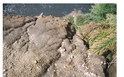
7.3     Maintenance of the ELS .................................................................................... 34
      7.3.1    What needs to be inspected?....................................................................................... 34
      7.3.2    How often shall it be inspected? .................................................................................. 34
      7.3.3    Why shall it be inspected? ............................................................................................ 35
      (i)      Liquid level in the ELS................................................................................................... 35
      (ii)     Grass mat cover............................................................................................................. 35
      (iii)    Access/filling/emptying points ...................................................................................... 35
      (iv)     Fencing and gates ......................................................................................................... 36
      (v)      Embankment examination ............................................................................................ 36
      (vi)     Equipment ....................................................................................................................... 36
      7.3.4    What is the recommended course of action if damage is observed? .................... 36
      (i)      Store liquid level............................................................................................................. 36
      (ii)     Grass mat........................................................................................................................ 36
      (iii)    Access/filling/emptying points ...................................................................................... 37
      (iv)     Fencing and gates ......................................................................................................... 37
      (v)      Embankments and subsoil liner................................................................................... 37
8     Health and safety .............................................................................................39
    8.1     Introduction.......................................................................................................... 39
    8.2     Health and safety issues for slurry/effluent stores ................................... 39
    8.3     Health and safety concerns for ELSs............................................................ 40
    8.4     Children and young persons ........................................................................... 40
    8.5     General health and safety references for agriculture ............................... 40
9     Appendix 1 Groundwater response matrix for ELSs .............................41
    9.1     Introduction.......................................................................................................... 41
    9.2     Vulnerability rating and aquifer classification ............................................ 41
    9.3     Groundwater response matrix for ELSs....................................................... 42
10 Appendix 2 Classifying a subsoil................................................................45
    10.1    Introduction.......................................................................................................... 45
    10.2    Atterberg limits.................................................................................................... 45
    10.3    Particle size distribution (PSD) test............................................................... 45
    10.4    Utilising the PSD curve and Atterberg limits .............................................. 46
    10.5    Subsoil field assessment tests ....................................................................... 46
      10.5.1   Field assessment of grading ........................................................................................ 46
      10.5.2   Field assessment of plasticity ...................................................................................... 46
      (i)      Cohesion and plasticity of fine fraction of coarse soils............................................. 46
      (ii)     Toughness of fine soils ................................................................................................. 47
      (iii)    Dilatancy test .................................................................................................................. 47
    10.6    Using results to classify subsoil .................................................................... 47
11 Appendix 3 ELS capacity calculations ......................................................51
    11.1    Slurry production................................................................................................ 51
    11.2    Regulatory slurry capacity requirement....................................................... 51
    11.3    ELS storage capacity......................................................................................... 53
    11.4    Net rainfall capacity calculation ..................................................................... 53
    11.5    ELS liquid volume calculation (worked example)...................................... 54

                                                                                                                                                4
12 Appendix 4 Site assessment form ..............................................................55
12.1 General details .................................................................................................... 55
12.2 Background information................................................................................... 56
12.3 Visual assessment ............................................................................................. 57
12.4 Trial hole ............................................................................................................... 58
12.5 Laboratory soil test results.............................................................................. 59
12.6 Sketch of site ....................................................................................................... 59
13 Appendix 5 Worked example........................................................................62
13.1 General details .................................................................................................... 62
13.2 Background information................................................................................... 63
13.3 Visual assessment ............................................................................................. 64
13.4 Trial hole ............................................................................................................... 66
13.5 Laboratory subsoil test results....................................................................... 66
13.6 Sketch of site ....................................................................................................... 67
13.7 Sizing the Grange ELS ...................................................................................... 67
13.7.1 Slurry capacity requirement.......................................................................................... 67
13.7.2 Precipitation capacity requirement .............................................................................. 68
13.7.3 Overall ELS volume ....................................................................................................... 68
13.8 Subsoil liner design ........................................................................................... 70
14 Appendix 6 References ..................................................................................72
LIST OF TABLES
5Table 2-1 Objectives and implications of site assessment ______________________________ 11
Table 2-2 Key environmental receptors and issues ___________________________________ 12
Table 2-3 Water quality of sample collected directly beneath compacted subsoil liner at pilot-
scale ELS at Teagasc Grange Research Centre (Scully, 2005) _________________________ 13
Table 3-1 Minimum subsoil requirements ____________________________________________ 21
Table 3-2 Desk study information and site assessment phases _________________________ 21
Table 5-1 Minimum requirements for configuration of an ELS___________________________ 25
Table 6-1 Ground pressure values for a sample of hydraulic excavators _________________ 31
Table 6-2 Compaction guidance using different compaction plant (Table in NRA 2005) ____ 32
Table 7-1 Recommended inspection schedule for ELS ________________________________ 34
Table 7-2 Embankment and subsoil liner remediation guidance_________________________ 38
Table 9-1 Vulnerability rating (DELG/EPA/GSI, 1999) _________________________________ 41
Table 9-2 Aquifer classification (adapted from DELG/EPA/GSI,1999)____________________ 41
Table 9-3 Matrix of groundwater protection zones (DELG/EPA/GSI, 2005) _______________ 42
Table 9-4 Response matrix for earth-lined slurry/effluent stores (ELSs) __________________ 42
Table 9-5 General groundwater response requirements for ELSs _______________________ 44
Table 10-1 Toughness characteristics for characterising the toughness of fine soils
(BS5930:1999) __________________________________________________________________ 47
Table 10-2 Field tests for classification of subsoils (GSI, 2001) _________________________ 50
Table 11-1 Estimated quantities of neat excreta produced by different classes of livestock (av.
weight animals) (adapted from Table 2, Schedule 2, GAPPW, 2005) ____________________ 51
Table 11-2 Proposed zonal configuration under European Communities (Good Agricultural
Practice for Protection of Waters) Regulations 2005 (adapted from GAPPW, 2005) _______ 51
Table 11-3 Proposed zonal configuration under European Communities Good Agricultural
Practice for Protection of Waters, 2005 (adapted from GAPPW, 2005)___________________ 52
Table 11-4 Average net rainfall during the specified storage period______________________ 53
Table 11-5 Worked example illustrating how the liquid capacity of an ELS may be calculated
(H. Scully, 2005) _________________________________________________________________ 54
Table 13-1 Groundwater and bedrock information obtained for proposed ELS site from the
Geological Survey of Ireland (www.gsi.ie) ___________________________________________ 65
Table 13-2 Details of nearest online borehole record to proposed ELS___________________ 65
Table 13-3 Minimum requirements for ELS (S131, DAF, 2005) _________________________ 68
Table 13-4 Teagasc Grange ELS dimensions ________________________________________ 68
Table 13-5 Store design calculations for Teagasc Grange ELS _________________________ 70
Table 13-6 Fencing requirements for Teagasc Grange ELS using S131 _________________ 70
LIST OF FIGURES
Figure 5-1 Basic configuration of an ELS (H.Scully) ___________________________________ 25
6Figure 5-2 Scenario A, B and C options for design of compacted subsoil liner in an ELS
(H.Scully) _______________________________________________________________________ 27
Figure 6-1 Example of how the required minimum no. of agitation points for an ELS may be
assessed _______________________________________________________________________ 33
Figure 7-1 Example of embankment breach caused by overtopping of embankment. ______ 35
Figure 7-2 Trees located within an ELS footprint (not permitted) ________________________ 35
Figure 7-3 Erosion on the inner embankment face of an ELS caused by careless filling of
store ___________________________________________________________________________ 36
Figure 10-1 Atterberg limits and related indices (Scully 2005) __________________________ 45
Figure 10-2 Flow chart to aid in classification of subsoils in Ireland ______________________ 50
Figure 11-1 Proposed zonal configuration under European Communities Good Agricultural
Practice for Protection of Waters, 2005 (adapted from GAPPW, 2005)) __________________ 52
Figure 13-1 Proposed ELS location (adapted from www.gsi.ie) _________________________ 65
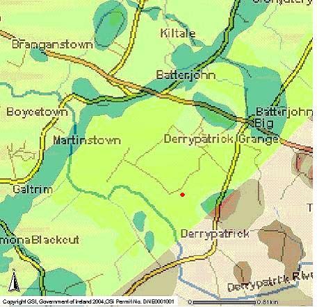
Figure 13-2 Geometrical design for earth-lined slurry/effluent store (ELS) at Teagasc Grange
Research Centre (H.Scully)________________________________________________________ 69
Figure 13-3 Scenario C ELS subsoil liner design (H.Scully) ____________________________ 71
Figure 13-4 Teagasc Grange ELS __________________________________________________ 71
71 Introduction
1.1 Introduction
This document outlines the principles and approach to the planning,
assessment, design, construction and operation and maintenance of earth-lined
slurry/effluent stores (ELSs) as detailed in Department of Agriculture and Food
Specification S.131: Minimum Specification for Earth-Lined Slurry/Effluent
Stores and Ancillary Works (S.131). It is designed to give information and
guidance concerning all stages of ELS sizing, assessment, design and
construction. Each section below outlines the scope and methodology of each
stage and more detailed information is given in the relevant chapters.
Agricultural activities and processes give rise to a range of liquid sources
including animal slurries, silage effluent, dairy washings and dirty water. The
safe management of these sources is an objective for all farmers. Sufficient
storage capacity for animal slurries shall be provided to enable safe
management of slurries during closed periods and when slurry cannot be
spread due to poor weather conditions. Conventional slurry storage
infrastructure requires significant investment to make up the slurry capacity
shortfall. ELSs are an internationally recognised form of storage for varying
types of effluents including those of industrial and agricultural origin and can be
used to successfully store animal slurry. It is important however, that the
objective shall always be good environmental management of the slurry and
effluent production on a farm. Before evaluating the capacity requirements for
any store, the client shall make every effort to make their farming operation as
efficient as possible by reducing the quantities of liquids requiring storage.
Diverting as much clean water as possible away from dirty water streams is an
example of how the storage capacity requirement may be reduced.
1.2 What is an earth-lined slurry/effluent store?
ELSs are subsoil-based structures which are used as a method of slurry
storage. They may be used to store neat, dilute or separated slurries and the
storage and settlement of dirty water. ELSs are typically < 20 m wide, between
20 to 50 m in length and 2.5 to 3.75 m deep. The shape of an ELS is often
governed by the location and the site characteristics. The tank is formed by
excavating soil and subsoil to formation level and using the excavated or
imported material to form surrounding banks and subsoil liner. A subsoil liner
is installed to protect the surrounding environment. The size of the store must
take into account the quantity of liquid which needs to be stored, precipitation
falling on the store, evaporation from the store and the freeboard required.
1.3 ELS role in the storage of animal slurry and effluent
By increasing the available slurry storage capacity on Irish farms, the need for
inappropriate landspreading is reduced, because farmers will have the capacity
to await more favourable landspreading times when the risk of overland flow is
reduced and the crop can gain maximum benefit from the nutrients contained in
the slurry. By maximising the utilisation of slurry nutrients, the farmers will
reduce their requirement for chemical fertilisers. Efficient recycling of nutrients
within the environment is encouraged. An ELS allows farmers to increase their
slurry storage capacities and consequently improve their farming practices.
81.4 Advantages and disadvantages of ELSs
Advantages:
• a sustainable design using local materials (where suitable)
• slurry/effluent storage capacity on farms can be greatly increased
• adaptable to the needs of the farmer
• low cost maintenance
• does not pose a significant threat to the environment when designed and
constructed properly
• good landscape fit, particularly on gently sloping sites
• toxic gases are not emitted into confined spaces therefore there is a
reduced risk to humans and animals
Disadvantages:
• requirement for competent site analysis and characterisation skills
• requirement for construction supervisor
• there are sites which will be unsuitable for construction of an ELS
• relatively high maintenance time
• there is an inherent risk in all slurry/effluent stores of drowning by humans
and animals.
1.5 The need for a guidance document for ELSs
The main purpose of this guidance document is to provide comprehensive
guidance for the design and construction of an ELS. While this document
provides the design guidance, a separate specification document (S131) is
available from the Department of Agriculture and Food for the construction of
ELSs. Farmers are reminded that they have a duty under the Safety, Health
and Welfare at Work Act, 2005 to provide a safe working environment on the
farm, including farm buildings, for all people who may work or enter that farm.
There is a further duty to ensure that any contractor, or person hired to do
building work, provides and/or works in a safe environment during construction.
The steps outlined in this guidance document, from the initial decision on the
appropriateness of an ELS to the final installation process, involve a variety of
choices at each stage. The choices made will reflect the particular approach of
the designer for particular locations, but once the steps outlined are followed,
the robustness and sustainability of the ELS is upheld. This document is
targeted primarily at Local Authority planners, site assessors, construction
supervisors, agricultural consultants and farm advisors. The guidance
document is available on the website of the Department of Agriculture and
Food (www.agriculture.gov.ie).
1.6 Overview of guidance document
Chapter 2: Site characterisation: general overview
Chapter 2 gives a general outline of the methodology which is employed when
carrying out a site characterisation, which includes a risk based assessment,
general site suitability requirements and some minimum design requirements.
Chapter 3: Undertaking the site assessment
This chapter gives guidance on how to carry out a specific assessment of a site
being considered for an ELS by collating and analysing data pertaining to site
location, farming practices, soil and subsoil type, groundwater protection
requirements and general planning information.
Chapter 4: Regulatory procedure
Chapter 4 summarises relevant national legislation and planning regulations
pertaining to obtaining planning permission for an ELS.
9Chapter 5: Earth-lined slurry/effluent store design
This chapter details the design requirements necessary to ensure that the ELS
is constructed to best meet the needs of the farmer with minimum impact on the
environment. Design details include tank volume, length, width, depth of slurry,
precipitation and evaporation requirements, freeboard, inner and outer bank
slopes, minimum bank width, overall tank footprint and requirements for subsoil
liner which is based on the recommendations of the site assessment.
Chapter 6: Earth-lined slurry/effluent store construction
Chapter 6 details the steps required for construction of an ELS. These include
site preparation, excavation, embankment and subsoil liner construction, filling,
agitation and emptying points, fencing, tractor access and external bank finish.
Chapter 7: Operation and maintenance
Guidance on routine maintenance checks is given including embankment
inspection and maintenance of freeboard levels.
Chapter 8: Health and safety
This section gives guidance on possible health and safety issues which may
arise including information on fencing, gates, access points and appropriate
signage.
Appendices
Appendix 1 gives a brief introduction to the groundwater protection response
matrix for ELSs and describes how it is utilised during site assessment and
characterisation. Appendix 2 contains guidance on classifying a subsoil using
BS 5930:1999. Appendix 3 tabulates excerpts from documents which assist
the designer in calculating the required slurry storage capacity of the proposed
ELS. Appendix 4 contains a full copy of the site characterisation form and
Appendix 5 gives a worked example of how the assessor and designer utilise
the specification and guidance document to investigate a proposed site, give
recommendations on the site suitability and design an ELS. Appendix 6
contains the references used in the preparation of this document.
102 Site characterisation: general overview
2.1 Introduction
Earth-lined slurry/effluent stores (ELSs) are a specific approach to the storage
of liquid animal manures and soiled water on farms. ELSs are a way of
increasing the slurry storage capacity on farms that is not excessively
expensive, but does not pose a significant threat to the environment. The
decision to use an ELS will be made on an integrated evaluation of
technological, environmental, economic, and logistical criteria, and personal
preference on the part of the farmer, but the suitability or otherwise of the site
will be of key importance in the decision making process. It is therefore
important that a systematic and logical approach is followed to allow the
suitability of the site to be assessed as early as possible in the decision
process, so that time and expense is not wasted unnecessarily. Any
development of an ELS will require planning permission. The Planning
Authority will need to be provided with adequate information in a standard,
easily understood and logical format to assess the proposed development.
Chapters, 2 & 3 provide guidance on how to assess site suitability with the
objective of collecting sufficient information to:
• determine if the ELS can be developed on the site
• demonstrate that the construction of an ELS will not create a negative
impact on the environment
• to provide adequate data to enable the optimal design to be achieved.
The approach is termed site characterisation. Site characterisation combines
various assessments including desk study, visual assessment and site tests to
satisfy the objectives.
2.2 Objectives of the site assessment
There are certain advantages associated with ELSs over other systems.
However, it is important that the raw materials to optimise these advantages
are available on the site, and it is important therefore, that the site assessment
is targeted, rigorous and comprehensive to ensure all areas are properly
assessed and that high risk areas are avoided.
Objective Implication for Site Characterisation
Protecting the environment Identifying the receptors at risk, locating the ELS
in suitable areas and applying adequate set back
distances
Providing adequate storage Ensuring that the nature and extent of the hazard
is fully understood
Not relying solely on engineering Ensuring that sufficient information is gathered to
measures to isolate the system from enable the risk to be controlled by natural
the environment protection, enhanced by engineering measures
Protection of groundwater Assessing whether in-situ material can be used
to build the ELS. Ensuring that the nature and
variation of subsoil properties are fully
understood
Table 2-1 Objectives and implications of site assessment
112.3 Risk based approach
When we interact with the environment, which by its nature can be variable and
heterogeneous, we cannot rely on 100% protection at all times. This means
we need to rely on risk minimisation. The concept of risk is therefore important
in the overall concept of site assessment and design. Risk based assessment
provides a framework for evaluating and managing pressures and impact on
identified receptors. The Hazard-Pathway-Receptor model is the
recommended approach. Risk can be defined as the likelihood or expected
frequency of a specified adverse consequence. Applied to ELSs it expresses
the likelihood of damage or contamination arising from the construction or
operation of an ELS (hazard). A hazard presents a risk when it is likely to
affect something of value such as groundwater or surface water (receptor). An
impact can only occur if a linkage (pathway) is established between the hazard
and the receptor. Protection, like risk, is a relative concept in the sense that
there is an implied degree of protection (absolute protection is not possible).
An increasing level of protection is equivalent to reducing the risk of damage to
the receptor. Moreover, choosing the appropriate level of protection
necessarily involves placing a relative value on the protected entity.
2.4 Key environmental receptors
In the context of an ELS the key environmental receptors include:
Receptor Issues
Groundwater Unless the store is properly constructed, there may be significant
percolation to the aquifer, which will have a resource value in
keeping with national groundwater protection criteria. In addition,
nearby drinking water supplies need consideration and protection
Surface water The risk of bank failure, resulting in transport of contaminated
material into a watercourse water will need to be assessed
Soil/subsoil The subsoil will form the sealing element of the ELS and will
provide the protection to the underlying aquifer. The subsoil also
has a role in attenuating pollutants
Flora and fauna Care will need to be taken to ensure that protected areas are not
impacted
Air Minor odours will be associated with the ELS, but shall not
significantly increase the odours over and above those already
associated with the farmyard.
Cultural heritage The desk study shall identify any known heritage sites. In general
ELSs shall not be built within the curtilage of heritage sites. Care
during construction must be exercised to eliminate damage to
possible undiscovered sites
Human The potential impact on the farm enterprise and neighbours needs
to be assessed.
Table 2-2 Key environmental receptors and issues
2.5 Hazard characterisation
2.5.1 General
The principal contaminants, which constitute the hazard, are related to animal
wastes (slurry), but may also include some farmyard dirty water, wash water
(principally dairy washings) and silage effluent. Microbial pathogens,
ammonia and nitrate pose the greatest threat to groundwater. In addition,
phosphate may impact on surface water.
122.5.2 Typical characteristics of effluent
It has been noted that the volumes of effluent that are generated can be very
variable. Similarly the chemical characteristics can also be variable. Typical
characteristics of slurry in uncovered stores are; N: 3.9 kg.m-3 and P: 0.6
kg/m-3 (DAF). Typical BOD values of slurry can be up to or over 20000 mg.L-1.
Because there will be some percolation from the store to the ground, the
ground and associated groundwater body will be the receptor.
Research was conducted at Teagasc Grange Research Centre to evaluate
the effectiveness of a compacted subsoil liner at protecting groundwater
(Scully et al. 2004). A pilot-scale ELS was constructed to enable sampling of
water directly beneath the compacted subsoil liner. The quality of the water
sampled from directly beneath a 0.5 m thick compacted subsoil liner is
presented in Table 2.3.
Parameter Concentrations (mg.L-1)
Mean Standard deviation Median
BOD 3.34 1.53 3.0
TON mg.L-1 4.58 2.01 5.21
Ammonia mg.L-1 N 0.127 0.048 0.1
Nitrate mg.L-1 N 4.58 2.02 5.2
Phosphorus mg.L-1 0.055 0.198 0.015
Chloride mg.L-1 37.15 14.33 34.2
Faecal coliforms / 100 mls none detected during sampling period
Table 2-3 Water quality of sample collected directly beneath compacted subsoil liner at
pilot-scale ELS at Teagasc Grange Research Centre (Scully, 2005)
Sealing of the pilot-scale ELS base to a permeability of 1 x10⁻⁹ m.s-1 was
achieved. Under a typical ELS (3.0m depth of slurry over 1.5 m compacted
subsoil liner when full), maximum velocity to groundwater could be expected to
be 0.00026 m3.m-2.d-1 using Darcy’s Law;
v = ki
where: v= velocity (m.s-1)
k = coefficient of permeability (m.s-1)
i= hydraulic gradient.
Therefore for a 1000 m2 ELS when full, the daily flow rate would be 0.26 m3.d-1.
132.6 Site suitability (general requirements)
There are a number of pre-requisites, which must be satisfied before
embarking on an assessment of the suitability of a site for the construction of
an ELS. These include:
2.6.1 Site restrictions
There are a number of restrictions, which shall be satisfied before embarking
on the construction of an ELS subject to Local Authority planning
requirements. A proposed ELS shall not be considered for:
• sites within 60 m of any well or spring used for potable water
• sites within either:
o (a) the inner protection zone of public water drinking supply source
(>10m3.d-1 or PE >50) (groundwater) where the vulnerability rating
is classified as extreme, or
o (b) where an inner protection zone has not been identified and the
vulnerability rating has been classed as extreme, within 300 m up
gradient of the abstraction point
• sites where the minimum design requirements (Clause A.4 of S.131)
cannot be achieved
• sites within 10 m of an open watercourse where slurry effluent can enter
• sites within 50 m of a lake
• sites within 15 m of a karst feature
• sites underlain directly by sand/gravel in vertical hydraulic continuity with
the main watertable
• sites underlain by peat or other unstable material that is impracticable to
remove
• sites liable to flooding
• sites where construction of the ELS will damage or destroy a site of
potential natural or cultural heritage value
• sites that are steeply sloping (greater than 1:5).
2.6.2 Minimum design requirements
• all ELS’s shall be underlain by at least 1.5 m of moderate or low
permeability subsoil, with the upper 0.5 m having a permeability of less
than 1 x 10⁻⁹ m.s-1
• where a regionally important aquifer is present the total thickness shall be
at least 1.5 m, with the upper 1.0 m having a permeability of less than 1 x
10-9 m.s-1
• where the required permeability in the upper 0.5 m or 1.0 m has to be
enhanced this shall be achieved by the construction of a compacted liner
as described in Clause C.6 of the technical specification (S.131)
• in cases where the site assessment indicates that the in-situ subsoil has a
clay content greater than 18%, is impervious (equivalent to a natural
permeability of 1 x 10⁻⁹ m.s-1), free from preferential flow paths (e.g.
rootlets, worm burrows, or cracks) and that the required depth of subsoil
(1.5 m minimum) is present, then the excavated portion of the tank will
require a 150 mm layer of compacted subsoil (4 passes) and plastering
with remoulded subsoil.
143 Undertaking the site assessment
3.1 Introduction
The purpose of site assessment is to determine the suitability of the site for the
construction of an earth-lined slurry/effluent store (ELS). This chapter details an
approach for completing the site assessment. The site assessment provides
the basis for the ELS design and the data collected will be used to optimise the
design and construction of the proposed ELS. A site assessment form for the
collation of data is given in the technical specification for ELSs (S131). This
shall be completed and will act as a check list, and aid in the decision making
process. The text below follows the layout of this site assessment form, and the
form (Appendix 4) should be referred to in combination with the text below.
3.2 Approach to site assessment
The following key steps must be undertaken:
• collation of background information
• visual assessment
• site tests
• decision process and preparation of recommendations.
3.3 Collation of supporting information
3.3.1 Preliminary consultation
The purpose of the preliminary consultation is to:
• establish the current slurry and dirty water management practice
• establish in general terms, what will be stored in the ELS
• provide the farmer with some general facts on the ELS
• establish the motivating factors for the project proposer/farmer wishing to
build an ELS.
A good understanding of the issue can be gleaned in a telephone
conversation or preliminary meeting with the farmer or his/her adviser. In
return useful information can be provided to the farmer on budget project
costs and other logistical items. The decision to consider building an ELS
usually originates with the farmer. He/she may involve an adviser in the
decision and procurement process. The farmer may have one or more
reasons for considering the use of an ELS, and these may include:
• insufficient existing storage
• improved environmental performance
• relative cost/benefit advantages when compared to other alternatives.
The nature of the material that will enter the tank needs to be established in
broad terms at this stage. When assessing the slurry storage capacity
requirements of the farmer, a number of logical steps must be followed to
ensure that volumes are accurately assessed. Information shall be sought
concerning the number of animals producing slurry on the farm. Using this
information, the amount of slurry produced on the farm may be calculated by
referring to the most up to date information on slurry production rates
(Appendix 3). Other effluent volumes (e.g. dairy washings, farm yard dirty
water, silage effluent etc.) may also be assessed. By examining the existing
slurry storage capacity on the farm and knowing the minimum storage period
required by regulatory bodies, a good approximation of the slurry storage
capacity of the proposed ELS can be made. It is important at this stage that
the store be sized to take account of any shortfall in slurry storage capacity
15(this may be discussed with the farmer/advisor). The broad design sizing
(see Chapter 5) can be discussed at this stage, to give the farmer an
indication of the approximate size of the tank and to ascertain if he/she is
willing to provide sufficient space to construct the tank, and if the ground and
topography can lend itself to ELS construction. The name, address and
contact details of the farmer shall be confirmed and some general items in the
form can be filled out at this time.
3.3.2 Collation of relevant environmental data
(i) General
The purposes of this section are to:
• obtain information relevant to the site
• identify targets at risk
• establish if there are site restrictions
• allow the ranking of sites if a number of possible sites are being
considered.
A desk study involves the assessment of available data pertaining to the site
and adjoining area that may determine whether the site has any restrictions
to the development of an ELS. The following information will need to be
collated and the form completed as necessary.
(ii) Topography
Base maps can be purchased from the Ordnance Survey of Ireland, or from
regional map shops. A set of maps suitable for planning applications, termed
a planning pack is the most suitable way to buy the maps and these can be
used later for the preparation of a planning application. The relevant
Discovery series 1:50,000 scale map will establish the regional topographical
context, showing relative slopes, surface water features and other relevant
topographical features. The grid reference for the site shall be determined,
and can be easily computed from the Discovery map. The best available
base map information is at scales of 1:2,500 and 1:10,000. These maps
provide useful information on the immediate topography and may identify
potential sites of natural or cultural heritage.
(iii) Surface water
The location of the nearest surface waters, their distance from the proposed
site and where relevant the designation (under national regulations) shall be
established.
(iv) Geological and hydrogeological
The existing source of water on the farm shall be established, i.e. whether
mains, private, or group scheme. The relevant geological and
hydrogeological information for the site shall be compiled. The Geological
Survey of Ireland (GSI) is the principal source of this information (www.gsi.ie).
This website lists available groundwater protection schemes. The GSI
produces maps of groundwater resources (aquifers) and vulnerability to
contamination (groundwater vulnerability). These are combined to produce a
map of groundwater protection zones. In general this information is available
from the website, but the relevant contact details are: The Groundwater
Section, Geological Survey of Ireland, Beggars Bush, Dublin 4. A national
aquifer map is available on the GSI website, and it is possible to zoom in to
the area in question and print the relevant excerpt if required.
16Note: If a complete groundwater vulnerability map (showing extreme, high,
moderate and low vulnerability areas) has not been produced by the GSI,
maps of extremely vulnerable areas, created by the Water Framework
Directive River Basin District (WFD RBD) consultants, will be available on the
GSI website. General soil and subsoil maps are available from Teagasc.
Existing data, available from the GSI includes location of outcropping bedrock
and karst features and existing depth to bedrock data from their well
databases. From this, areas of shallow subsoils (rock within 1.0 m of surface)
can be delineated. This can then be used in the desk study. Where
information from the GSI well and karst databases is used in a desk study,
the townland in which the feature is located (or more specific location if
available) shall be highlighted on a map. The data, when compiled shall be
compared to the groundwater protection response matrix in Appendix A to
establish the preliminary groundwater protection response for the proposed
development.
Flora, fauna and cultural heritage
The relevant Local Authority will have a list of designated NHA’s, candidate
SAC’s and an inventory of protected structures, where this is relevant. If
more detail is required government bodies such as the Department of
Environment, Heritage and Local Government (DEHLG) and the Office of
Public Works (OPW), can be contacted to discuss particular areas. If areas
are identified, the extent of the restricted area shall be plotted on a map and
a brief description provided in the form.
(vi) Drainage
The drainage patterns of the area being examined are critical, and field
drainage maps for the particular area shall be sought from the farmer or their
advisor, and general information on the density of drainage in the area, can
be determined from the topographical maps. Reference to topographical
maps produced prior to the 1950’s will indicate previously wet areas that may
have since been drained.
(vii) Public utilities
The Local Authority shall be consulted with regard to the location of public
water supplies and water mains in the area. Locations of gas lines, electricity
cables, and communications networks need to be established in consultation
with the relevant utilities. The relevant contact numbers for each utility can
be found in the phone book. The status of these shall be assessed at this
stage, and the need for further investigation highlighted if necessary.
(viii) General planning
The county development plan shall be consulted to establish if there are any
restrictions to developments of this sort. This will be available for
consultation at the Local Authority offices. The development plan may
indicate set back distances that have been decided unilaterally by the Local
Authority.
3.3.3 Interpreting the results of the background information
• having reviewed the topographical maps and identified surface water
features, possible topographical constraints, and the presence of any
mapped areas of heritage you will have discovered and collated any/all
information relating to surface water and heritage from the relevant
sources
17• having collated and examined this information, potential constraints such
as significant archaeological, natural heritage and/or historical features
within the proposed site may be highlighted. To avoid accidental damage,
a trial hole assessment shall not be undertaken in areas which are at or
adjacent to significant sites (e.g. SAC’s, NHA’s)
• the geological information collated will have indicated the potential of
encountering karst or high resource value aquifers. The subsoils
information collated from subsoil maps, permeability maps, vulnerability
maps and other subsoil information sources will have highlighted the
possibility of encountering gravel or potentially low permeability material
• once the aquifer and vulnerability classes are established, reference to
the groundwater protection matrix (Appendix 1) will allow determination of
the appropriate response and the requirements associated with that
response. Areas classed as having a ‘low’ vulnerability are likely to be
underlain by low permeability subsoil. The on-site assessment will later
confirm or modify such responses
• you will have established the prevailing climatic data, and established any
constraints relating to land drainage, utilities, and planning constraints
• any information on satisfactory or unsatisfactory local experience with
ELSs can be incorporated at this time to complete the desk study
assessment.
By this stage you may be in a position to eliminate sites that present
insurmountable constraints.
3.4 Visual assessment
The purpose of the visual assessment is to:
• verify desk study findings
• make an on-site assessment of the hazard
• evaluate the sensitivity of the identified receptors
• finalise the selection of the preferred location.
3.4.1 On-site hazard evaluation
Photographs shall be taken on the site, to record the general layout and
structures, and various features of interest. It is important that the farmer is
present during this process to discuss the various changes in farm activities
that occur through the year.
3.4.2 Visual assessment of receptors
(i) Topography and landscape fit
A survey which will incorporate relevant site levels, minimum distances etc.
shall be undertaken to survey the proposed ELS site. The survey information
will be used principally in the design process, to make optimum use of
topography and minimise earth works cost. The topographical survey will
also allow the production of sections through the site, which will aid
construction planning and costing.
The landscape position reflects the location of the site in the landscape (e.g.
crest of hill, valley, slope of hill) and ideally the site shall be down slope of the
farmyard area to allow gravity flow of slurry to the ELS. If it is not it will be
necessary to pump or haul the slurry/soiled waters to the store. A general
overview of landuse, density of dwellings, surface water ponding,
waterbodies, drainage, vegetation, and condition of the ground shall be
18made, and the relative distances of potential receptors from the ELS
established.
(ii) Cultural heritage
Using the information from the desk study, a visual assessment of the site
shall be undertaken and the potential risk assessed. If the desk study had
identified any protected sites nearby, then the assessment will need to be
more thorough. Photographs shall be taken for reference.
(iii) Human
Location of dwellings or other places of collection such as nearby schools,
churches, hospitals, etc. shall be established and their distance from the ELS
determined. Overhead wires, poles and any other utilities shall be marked on
drawings.
(iv) Flora and fauna
Using the information from the desk study, a visual assessment of the site
shall be undertaken and the potential risk assessed. The vegetation
indicators shall be described and photographed. Trees that may potentially
be close to the ELS shall be marked on drawings.
(v) Surface water
The density of surface water features shall be noted as this will give an
indication of the relative permeability of the ground. The characteristics of
the nearest watercourse shall be described. Other surface water features
such as ponding, lakes, beaches, natural wetlands, streams and drainage
ditches shall be identified.
(vi) Drainage systems
Sites that may once have been wet will require special attention, because of
the possibility that existing drainage pipes may be in place, which could result
in short-circuiting of the system. This shall be evaluated as part of the site
assessment.
(vii) Groundwater
Existing domestic and farm wells within 100 m and public water supplies
within 300 m of the proposed site shall be identified and their distance and
location in terms of groundwater flow direction estimated. Water table levels
may possibly be determined as part of the trial hole programme. Baseline
groundwater quality data shall be collected at this time if considered
appropriate.
(viii) Climate
The prevailing wind direction across the proposed ELS shall be identified,
and the sensitivity of any receptors downwind identified. Any localised
rainfall conditions shall be particularly noted.
(ix) Soil and subsoils
Any areas of outcropping rock shall be identified and examined. Road
cuttings and any open excavations in the vicinity of the site shall be
examined, to provide information on the subsoil profile. Similarly, the shape
19You can also read