HBK-608FP-EU2 CIRCUIT BOARD - TECHNICAL DOCUMENTATION - ITOH DENKI

Page created by Stephen Wood
 
CONTINUE READING
HBK-608FP-EU2 CIRCUIT BOARD - TECHNICAL DOCUMENTATION - ITOH DENKI
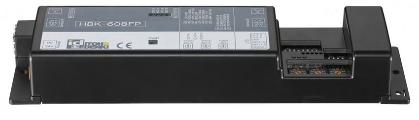
Circuit Board
HBK-608FP-EU2
 Technical documentation
HBK-608FP-EU2 CIRCUIT BOARD - TECHNICAL DOCUMENTATION - ITOH DENKI
Summary
1. Presentation of the PowerMoller range				Page 3
2. Presentation of the circuit board					Page 4
     General description
     Electric diagram
     General specifications
     Dimensions

3.Technical data with PM605KT motorized roller			Page 6
     PM605KT - Speed code 15
     PM605KT - Speed code 28
     PM605KT - Speed code 55

4. Location and specifications of items				Page 9
     Location of items
     Specifications of connectors
     Connector CN1 - 24 VDC power supply
     Connectors CN101-CN201 - Motor
     Connectors CN301-CN401 - Sensor
     Connectors CN302-CN402 - Communication cable
     Connector CN4 - Input / Output (I/O)
     Led display - PWR
     Leds CTRL and SEN A/B
     Leds MOT A/B and STS A/B
     Output error signal
     Types of errors and solutions
     Dip-switches SW1 - Selection and configuration of functions
     Dip-switches SW2 - Selection and configuration of functions
     Rotary dip-switches SW3 and SW4
     Rotary dip-switch SW5
     Forced control

5. Timers								Page 23
     Run holding timer
     Sensor timer
     Jam timer
     Initialisation

6. Functions and settings						Page 25
     Transfer modes
     Synchronization
     Odd number of motorized rollers
     «Forced stop» function
     «Forced start» function
     Setting logic flow direction relative to load move direction
     Setting motorized rotation direction relative to logic flow direction
     Speed setting
     Example of setting SW and I/O signals

Annexe 1 : Incorporation declaration					Page 35

HBK-608FP-EU2            Technical documentation
                                                                  2          Original notice - T1.8
HBK-608FP-EU2 CIRCUIT BOARD - TECHNICAL DOCUMENTATION - ITOH DENKI
1. Presentation of the Power Moller® product range
                                                                         solutions
  Controls                                           Motorized rollers                                                 Modules

Standard circuit board                                   DC Brushless                                                  90° transfer

                                                                                                                                      HBR-605
      CB016     CB016B                                                                                                 F-RAT-S250     CBM-105
                                                                                                                                      CBR-306

     CBM-105                                                                                                                          HBR-605
                                                                                                                       F-RAT-S300     CBM-105
                                           External                         Integrated                                                CBR-306
                            Replacing
     CBK-109 CBK-109B       CB030
                                        circuit board                      circuit board                                              CBK-109
                                                                                                                                      CB016B
                                                                                                                   F-RAT-NX75         HBM-201
      CB018                                                                                                                             IB-E
                                                                                                                                        IB-P

     CBV-108

                                                                                                                       45° transfer

  ZPA circuit board
                                                                                                                                      CBM-105
                                                                                                                         POP-UP       CBR-306

      HB510     HB510B                      Ø50                                            Ø50

                                                              CBM-105
     HBK-608                              PM500 FE
                                                                                                        B&W AS-i 3.0
                                                               HB510                   PM500 XE           Wenglor
                                                                IB-E

     HBV-609                                                  CBV-108                                   B&W AS-i 3.0
                                          PM500 VE            HBV-609                  PM500 XP           Wenglor
                                                               IB-P

                                                                                                       PEPPERL-FUCHS
                                          PM500 FE-B
                                                              CB016B                   PM500 XK           AS-Interface
                                                              HB510B                                     B&W AS-i 3.0
 Module circuit board
                                                                                                       PEPPERL-FUCHS
                                                                                       PM500 XC           AS-Interface
                                           Ø60,5                                                         B&W AS-i 3.0
     HBR-605

                                                              CBM-105
     CBR-306                              PM605 FE             HB510
                                                                                       Ø60,5
                                                                IB-E

                                                              CBV-108                                   B&W AS-i 3.0
     HBM-201                              PM605 VE            HBV-609                  PM605 XE           Wenglor
                                                               IB-P

                                                                                                        B&W AS-i 3.0
                                          PM605 FE-B
                                                              CB016B                   PM605 XP           Wenglor
                                                              HB510B
  Network controller
                                                              CBK-109
                                                              HBK-608
                                          PM605 KT              IB-P
       IB-E                                                     IB-E

                                          PM605 KT-B          CBK-109B
       IB-P

                                            Ø32

                                          PM320 HS             CB018

   Corresponding circuit board            Compatible module / sensor         Max load to be conveyed         Mechanical brake version

HBK-608FP-EU2               Technical documentation
                                                                  3                                                    Original notice - T1.8
2. Presentation of the circuit board
The circuit board HBK-608 with control logic of zones (Zero Pressure Accumulation ZPA) allows traceability
of load to transport. It can control 1 or 2 motorized roller, with the possibility of selecting the acceleration or
deceleration time. This function is useful for transferring pallets loaded in height in the best conditions.

           General description
                                                   • Fasteners
                                                          - 2 M4 x 15 cross-head screws
                                                          - 2 M4 washers
                                                          - 2 M4 nuts

                                                   • 1 connector WAGO 231-302/026-000 (2 points)

                                                   • 1 connector WAGO 733-106 (6 points) (in option)

                                                   • 2 connectors WAGO 733-103 (3 points)

                                                   • 1 communication cable (in option)
Compatible motorized rollers serie : Serie PM605KT

The circuit board HBK-608FP could be associated with 1 or 2 motors.

           Electric diagram
                                                                          Motorized roller

                                                                                  Free roller

                                                                                    Sensor

                                                                                    Communication cable

                                                                            Circuit board
                                                                                                MOTOR B
                                                          MOTOR A

                                                                    Synchronization Motor B / Output sensor
                                                                    Synchronization Motor A / Output sensor
                                                                                                Output error
                                                                                 Start / Stop forced Motor B
                                                                                 Start / Stop forced Motor A
                                                                                     Direction / Reset Error

   HBK-608FP-EU2         Technical documentation
                                                        4                                                      Original notice - T1.8
General specifications

Nominal voltage                             24VDC ± 10%
Static current                              0.6A
Current limitation                          7A
Motor acceleration time                     200ms
Protection index                            IP20
Protection                                  Integrated 10A fuse
                                            Against inversion of polarity (24 V and 0 V)
                                            Thermal protection (95°C for the circuit board, 105°C for the motor)
Input voltage on connector CN2              < 1V for NPN
if different to 0 or 24V                    > 15V for PNP
Sensor input (sensor not supplied)          NO contact (normally open), 24 V, max. 35 mA

Power supply                                TBTS 24VDC ± 10% - ripple < 10%
                                            A stabilised power supply is recommended
Environment                                 Temperature range 0 / +40 °C
                                            Relative humidity < 90% condensation-free (avoid thermal shocks)
                                            Neither corrosive nor explosive atmosphere
                                            Vibrations
3. Technical datas for motorized roller PM605KT
                           PM605KT - Speed code 15
                                            Tangential force                Torque                          Current
                              V (m/min)
                                                 (N)                         (Nm)                             (A)                            Rated output           Rated input
                SW3/4
                                                                                                                                                 (W)                   (W)
                               No load     Nominal     Starting     Nominal     Starting      No load       Nominal         Starting

                    9               17,2   155,7                     4,71                       0,8           3,2                                52                     77
                    8               15,8   155,7                     4,71                       0,7           2,9                                48                     71
                    7               14,3   155,7                     4,71                       0,7           2,7                                43                     64
                    6               12,9   155,7                     4,71                       0,6           2,5                                39                     59
                    5               11,5   155,7                     4,71                       0,6           2,2                                35                     54
                                                        884,5                   26,75                                         7,0
                    4               10,0   155,7                     4,71                       0,5           2,0                                30                     47
                    3               8,6    155,7                     4,71                       0,5           1,7                                26                     42
                    2               7,2    155,7                     4,71                       0,4           1,5                                22                     36
                    1               5,7    155,7                     4,71                       0,4           1,3                                17                     30
                    0               4,3    155,7                     4,71                       0,3           1,1                                14                     27

Reduction ratio : 1/54,87

                                                                  PM605KT (Nominal speed:
                                                                                        15) with HBK - 608
               20                                                                                                                                                       8.00
                                                   Speed vs Tangen�al force                                                            Current vs Tangen�al force
               18
                        17.2m/min                                                                                                                                       7.00

               16
                                                                                                                                                                        6.00
                                                 17.2m/min
               14
                        12.9m/min
                                                                                                                                                                        5.00
               12
Speed[m/min]

                                                         12.9m/min
                                                                                                                                                                               Current[A]

               10                                                  8.6m/min                                                                                             4.00
                        8.6m/min
                8
                                                                                                                                                                        3.00
                                                                       4.3m/min
                6
                                                                                           4.3m/min                                                                     2.00
                4

                                                                                                                                                                        1.00
                2

                0                                                                                                                                                       0.00
                    0          100         200          300            400           500              600             700              800            900           1000

                                                                                Tangen�al force[N]

               HBK-608FP-EU2               Technical documentation
                                                                                      6                                                                Original notice - T1.8
PM605KT - Speed code 28
                                            Tangential force                 Torque                        Current
                              V (m/min)
                                                 (N)                          (Nm)                           (A)                        Rated output       Rated input
                SW3/4
                                                                                                                                            (W)               (W)
                               No load     Nominal      Starting     Nominal      Starting   No load       Nominal     Starting

                    9               35,0    76,6                      2,32                     0,8           3,2                            52                   77
                    8               32,1    76,6                      2,32                     0,7           2,9                            48                   71
                    7               29,2    76,6                      2,32                     0,7           2,7                            43                   64
                    6               26,2    76,6                      2,32                     0,6           2,5                            39                   59
                    5               23,3    76,6                      2,32                     0,6           2,2                            35                   54
                                                         435,2                    13,16                                    7,0
                    4               20,4    76,6                      2,32                     0,5           2,0                            30                   47
                    3               17,5    76,6                      2,32                     0,5           1,7                            26                   42
                    2               14,6    76,6                      2,32                     0,4           1,5                            22                   36
                    1               11,7    76,6                      2,32                     0,4           1,3                            17                   30
                    0               8,7     76,6                      2,32                     0,3           1,1                            14                   27

Reduction ratio : 1/27

                                                                   PM605KT (Nominal speed:
                                                                                         28) with HBK - 608
               40                                                                                                                                                    8.00
                                                     Speed vs Tangen�al force                                                     Current vs Tangen�al force
                        35m/min
               35                                                                                                                                                    7.00

               30                                    35m/min                                                                                                         6.00

                        26.2m/min
               25                                                                                                                                                    5.00
                                                            26.2m/min
Speed[m/min]

                                                                                                                                                                            Current[A]

                                                                     17.5m/min
               20                                                                                                                                                    4.00
                        17.5m/min

               15                                                                                                                                                    3.00
                                                                     8.7m/min

               10                                                                                                                                                    2.00
                                                                                8.7m/min
                5                                                                                                                                                    1.00

                0                                                                                                                                                    0.00
                    0             50       100            150           200            250           300             350          400            450           500

                                                                                   Tangen�al force[N]

               HBK-608FP-EU2               Technical documentation
                                                                                        7                                                        Original notice - T1.8
PM605KT - Speed code 55
                                         Tangential force                 Torque                        Current
                           V (m/min)
                                              (N)                          (Nm)                           (A)                Rated output       Rated input
    SW3/4
                                                                                                                                 (W)               (W)
                            No load    Nominal      Starting     Nominal      Starting      No load    Nominal    Starting

               9              65,4      43,1                       1,30                        0,8       3,2                     52                  77
               8              60,0      43,1                       1,30                        0,7       2,9                     48                  71
               7              54,5      43,1                       1,30                        0,7       2,7                     43                  64
               6              49,1      43,1                       1,30                        0,6       2,5                     39                  59
               5              43,6      43,1                       1,30                        0,6       2,2                     35                  54
                                                     245,0                     7,41                                 7,0
               4              38,2      43,1                       1,30                        0,5       2,0                     30                  47
               3              32,7      43,1                       1,30                        0,5       1,7                     26                  42
               2              27,2      43,1                       1,30                        0,4       1,5                     22                  36
               1              21,8      43,1                       1,30                        0,4       1,3                     17                  30
               0              16,3      43,1                       1,30                        0,3       1,1                     14                  27

Reduction ratio : 1/14,44

                                                                     PM605KT (Nominal speed:
                                                                                           55) with HBK - 608
               70                                                                                                                                                8.00
                           65.4m/min                           Speed vs Tangen�al force                                       Current vs Tangen�al force

                                                                                                                                                                 7.00
               60

                                                     65.4m/min
                                                                                                                                                                 6.00
               50
                           49.1m/min
                                                                                                                                                                 5.00
                                                               49.1m/min
Speed[m/min]

               40

                                                                                                                                                                        Current[A]
                                                                     32.7m/min
                           32.7m/min                                                                                                                             4.00

               30
                                                                                                                                                                 3.00
                                                                           16.3m/min

               20
                                                                                                                                                                 2.00
                                                                                   16.3m/min

               10
                                                                                                                                                                 1.00

                   0                                                                                                                                             0.00
                       0                   50                      100                       150                  200              250                     300

                                                                                         Tangen�al force[N]

               HBK-608FP-EU2                     Technical documentation
                                                                                             8                                              Original notice - T1.8
4. Location and specifications of items
             Location of items
                                                  STS A / MOT A
                                                  STS B / MOT B

                                                 PWR
                                                         CTRL / SEN A / SEN B

Connectors et switch                                              Leds

CN1 		       Supply connector 24VDC                               CTRL		               Supply to the logic board
CN101-201    Connector motor 12 pins                              PWR                  Supply circuit board
CN301-401    Connector sensor                                     MOT A / MOT B        Motor A/B connected and ready
CN302-402    Connector communication cable                        STS A / STS B        State motor A/B
CN4		        Connector Input/Output (I/O)                         SEN A / SEN B        Visualization sensor state
SW1 		       Dip switch 1
SW2 		       Dip switch 2
SW3-SW4      Rotary switch (fixed speed selection)
SW5		        Rotary switch (temporisation selection)

             Connector specifications

                           Circuit board side                                   Cable side
                                                          WAGO 231-302 (I = 10A max)
Supply 24VDC - CN1          WAGO 231-532
                                                 Wire cross-section 0,08~2,5mm² (AWG : 28~12)
                                                          WAGO 733-103 (I = 4A max)
Sensor CN301-401            WAGO 733-363
                                                 Wire cross-section 0,08~0,5mm² (AWG : 28~20)
Input / Output CN4                                        WAGO 733-106 (I = 4A max)
                            WAGO 733-336
    Option                                       Wire cross-section 0,08~0,5mm² (AWG : 28~20)

  HBK-608FP-EU2        Technical documentation
                                                           9                                             Original notice - T1.8
Connector CN1 - 24VDC power supply
                                                     • 24 V dc switch-mode power supply, which can accept an
                                                     overcurrent of 150% for 3 to 5 s, is recommended.
                                                     • The +24 V dc circuit is protected by a 7A fuse.
                                                     • Connector WAGO 231-302, wire-cross section 2,5mm² max
                                                     (AWG : 28~12)

 0 VDC                                                    Provide a power supply that is sufficiently powerful in function of
24 VDC                                               serie, type, operation and number of motorized rollers to be powered
                                                     simoultaneously.
                      CN1

The stabilized power supplies 24V shall be sized according to the number of motorized rollers that shall work. It is
possible to link some group of motorized rollers to the power supplies. These groups being link together thanks to
communication cable.

                            Circuit board                      Switch point                  Communication cable

     HBK608      HBK608        HBK608       HBK608         HBK608       HBK608      HBK608         HBK608       HBK608

                                                              Supply wiring
                               Supply                                                              Supply
                                 N                                                                  N+1

    It is mandatory to link the 0V in between the power supplies. They shall be controlled simoultaneously to avoid
creating problem in transition point.

    Make sure that the power supply is OFF befor plugging / unplugging the motor connector CN101-CN201.

    Don’t stop the motorized roller operating by powering off the circuit board.

   HBK-608FP-EU2            Technical documentation
                                                              10                                            Original notice - T1.8
Connectors CN101-CN201 - Motor

              CN101
                                                                     CN201
• CN101 : Connector motor A
• CN201 : Connector motor B

• Connector JST XHP-12 - 12 pins

    Do not disconnect the motor connector during operating.

             Connectors CN301-CN401 - Sensor

                                                                                                       0V
  24V
                                                                                                       IN
   IN
                                                                                                       24V
  0V

                CN301
                                                                                CN401

    Use a sensor type NO (open contact)

• Connector WAGO 733-103, wire-cross section 0,08 - 0,5 mm² max (AWG : 28~20)
• Current max : 35mA
• CN301 : Zone A
• CN401 : Zone B

  HBK-608FP-EU2         Technical documentation
                                                      11                                Original notice - T1.8
Connectors CN302-CN402 - Communication cable
   CN302                                                                                                     CN402

                                                               CN402
                                      Flow direction

                                                                                                    Communication
                                                                                                       cable

                                                CN302

    Always connect the connector CN302 circuit
board to the connector CN402 of another circuit
board..
                                                         • Cables with connector RJ45 Cat 5e (in option)
                                                              Cable lengths (mm)               Reference
    The communication cable must not be
                                                                       1000                CCOM-HB5X-1000
connected to the circuit board of the last zone.
                                                                       2000                CCOM-HB5X-2000
                                                                       3000                CCOM-HB5X-3000

It ensures :

      - State sensor reception and transmission, start / stop of motor located upstream or downstream of the
      zone concerned.
      - Transmission of flow direction signal, reset error signal all circuit boards interconnected.
      - Reception and transmission of error signal, impulse signal.

Number of HBK-608 to connect by communication cable is not limited, but delay time accrued :

      - by error signals (3ms to 15 ms per error signal according to type and per circuit board)
      - by flow direction signal «DIR» (20ms per circuit board)
      - by Reset signal (20ms per circuit board)

   HBK-608FP-EU2          Technical documentation
                                                        12                                     Original notice - T1.8
Connector CN4 - Inputs / outputs (I/O)

                                                                  • Connector WAGO 733-106, Wire cross-section 0,08-
                                                                  0,5mm² (AWG : 28-20)
                                                                  • Input signal : 7,3mA
                                                                  • Output signal : open collector 25mA max.

                            CN4

  Termi-         Function             Indication                                          Description
   nal
                                                      Reverse load transfer direction and logic
                                                      OFF (no signal) = load transfer direction and logic from right to left (circuit board
             Transfer and logic
                                          DIR         front view)
                 direction
 Terminal                                             ON (24V signal) = load transfer direction and logic from left to right (circuit board
    1                                                 front view)
                                                      Signal to reset the error
                 Reset error             RST          Sent a 24V signal at least 100 ms to reset error
                                                      This signal is sent to all the circuit board linked by communication cable
 Terminal       Start / Forced                        Forced start or stop of Motor A (see configuration SW2-3) with input on connector
                                      STOP/RUN A
    2           Stop Motor A                          CN4-2
 Terminal       Start / Forced                        Forced start or stop of Motor B (see configuration SW2-4) with input on connector
                                      STOP/RUN B
    3           Stop Motor B                          CN4-3
                                                      Sent signal when a d’un signal when a fault occurs
 Terminal                                             Type of signal depend on selector SW1-8
                    Error                ERR*
    4                                                 If SW1-8 = ON  Impulse output to identify the error with PLC
                                                      If SW1-8 = OFF  Sent signal when a fault occurs
              Synchronization                         Signal sent when Motor A start to synchronize another motorized roller (see confi-
 Terminal      with Motor A                           guration SW2-1)
                                        OUT A*
    5        State sensor zone                        Signal sent when the object is detected by sensor of zone A
                     A                                (see configuration SW2-1)
              Synchronization                         Signal sent when Motor B start to synchronize another motorized roller (see confi-
 Terminal      with Motor B                           guration SW2-2)
                                        OUT B*
    6        State sensor zone                        Signal sent when the object is detected by sensor of zone B
                     B                                (see configuration SW2-2)

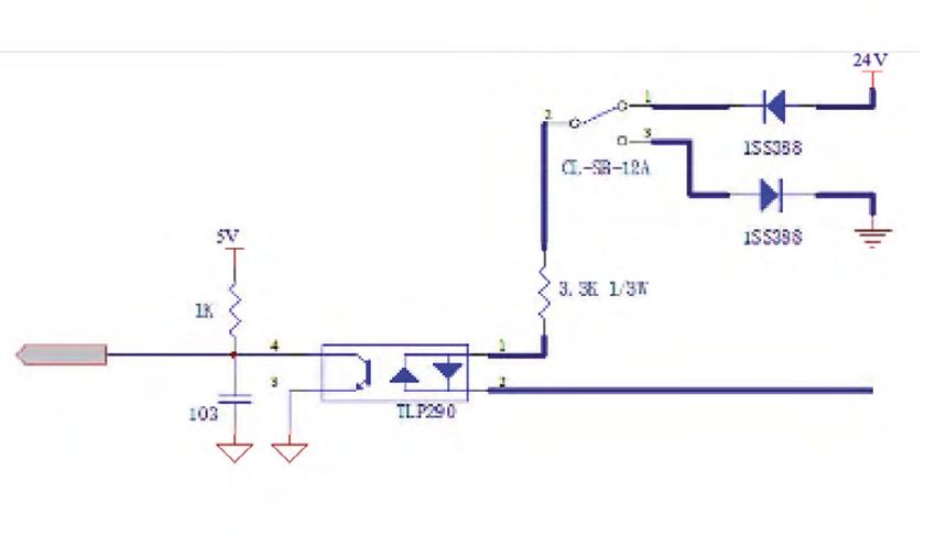
* If output is connected to inductive load (Ex. Relay coil , solenoid , actuator , etc . ), make sure to protect output from Back voltage with
a free-wheeling diode.

                                                     Internal circuit diagram

                                                                                                                         Output signal
                                                                                                                         Terminals 5 and 6
                                           Input signal
                                           Terminals 1~4

   HBK-608FP-EU2                  Technical documentation
                                                                     13                                                 Original notice - T1.8
Led display - PWR

                                                                             On
                                                                             Off
                                                                             Flashing at 1Hz
                                                                             Flashing at 6Hz

                                                                             Flashing at 6Hz and off alternate

                         Green Led                  State
LED            PWR                         Circuit board unpowered
                                                                                   6 Hz         Off          6 Hz
                                            Circuit board powered                  0,25s       1,5s          0,25s

           Leds CTRL and SEN A/B

        LEDS

           Indication                LED
  LED                                                                              State
                            Green          Orange
                                                                          Circuit board unpowered
        CTRL
                                                                           Circuit board powered
                                                                      Sensor OFF. No load on zone A

        SEN A                                                       Sensor ON. Load presence on zone A

                                                                           Jam default on zone A

                                                                      Sensor OFF. No load on zone B

        SEN A                                                       Sensor ON. Load presence on zone B

                                                                          Jam default on zone B

HBK-608FP-EU2           Technical documentation
                                                     14                                             Original notice - T1.8
Leds MOT A/B and STS A/B

 LEDS

           Indication                LED
 LED                                                                   State
                             Green         Red
                                                                  Motor A stopped
                                                                    Motor A run

                                                       Low voltage default / Fuse out of order

        STS A                                                  Motor A disconnected

                                                                 Blocking motor A

                                                       Thermal fault (circuit board or motor)

                                                              Induced current default

                                                               No motor A connected
        MOT A
                                                           Motor A connected and ready
                                                                  Motor B stopped
                                                                    Motor B run

                                                       Low voltage default / Fuse out of order

        STS B                                                  Motor B disconnected

                                                                 Blocking motor B

                                                       Thermal fault (circuit board or motor)

                                                              Induced current default

                                                               No motor B connected
       MOT B
                                                           Motor B connected and ready

HBK-608FP-EU2           Technical documentation
                                                  15                                    Original notice - T1.8
«Error signal» output

Terminal 4 of connector CN4-4 sent error signal depends of type of output signal selected by SW1-8 :
                                      ON

SW1-8 «ON» : impulse output
                                                                     OFF

SW1-8 «OFF» : sent 24V signal when a fault appears                         , on logic PNP (SW1-3 «ON»)
                                            SW1-8
              SW1-3

                                                 CN4
                                12 3 45 6

                                                            Error signal
                                             

In the case of impulse output, priority order and frequency depending on the type of error are:

  Priority            Type of error                    Frequency (ms)
     1       Low power supply voltage default                   40
     2           Connexion motor default                        60
     3            Blocking motor default                        80
     4          Circuit board thermal fault                    100
     5              Motor thermal fault                        120
     6            Induced voltage defeult                      140
     7                  Jam error                              160

Reset error signal occurs :

- Or by injection of the signal «RST» on terminal CN4-1, with SW1-1 position on «ON»

                                                       ON

                                             SW1-1

                                                 CN4
                                12 3 45 6

                                                                Must be injected ≥100ms

- Or by «Start / Stop forced» on terminals CN4-2 or CN4-3, with SW5 position on «0»

                                            SW5 : 0

                                                 CN4
                                12 3 45 6

                                                            Start / Stop
                                             

   HBK-608FP-EU2          Technical documentation
                                                                 16                                      Original notice - T1.8
Types of errors and solutions

                                          Symptoms                                                  Reset error signal
               Type of error                                           Solution
                                           Causes                                                 Restart motorized roller
                   Low power                                                              Injection signal «RST» on terminal CN4-1 or
                                    Voltage ≤15VDC for more       Secure the supply
                 supply voltage                                                                        «Start / Stop forced»
                                            than 0.1s           voltage above 18VDC
Alimentation

                     default                                                                      on terminals CN4-2 or CN4-3
                                    Overvoltage over 40 VDC     Get off the motorized     Injection signal «RST» on terminal CN4-1 or
                     Induced
                                     for 2 seconds or more      roller voltage below                   «Start / Stop forced»
                 voltage default
                                         60VDC for 0.1s                30 VDC                     on terminals CN4-2 or CN4-3
                   Fuse out of
                                                            Turn off the power and replace the circuit board
                     order
                                                                                          Injection signal «RST» on terminal CN4-1 or
Echauffement

                  Circuit board     Circuit board temperature
                                                                                                       «Start / Stop forced»
                  thermal fault           above 95 ° C.
                                                                 Stop the motorized               on terminals CN4-2 or CN4-3
                                                                 roller and let it cool   Injection signal «RST» on terminal CN4-1 or
                 Motor thermal      Motor temperature above
                                                                                                       «Start / Stop forced»
                     fault                  105 ° C.
                                                                                                  on terminals CN4-2 or CN4-3
                 Motorized roller                                                         Injection signal «RST» on terminal CN4-1 or
                                        Motorized roller            Connect the
                   connexion                                                                           «Start / Stop forced»
                                         disconnected              motorized roller
                     default                                                                      on terminals CN4-2 or CN4-3
                                                                                          Injection signal «RST» on terminal CN4-1 or
Autres

                    Blocking        Motorized roller blocked
                                                                                                       «Start / Stop forced»
                 motorized roller     for more than 0.5s
                                                                                                  on terminals CN4-2 or CN4-3
                                                                                          Injection signal «RST» on terminal CN4-1 or
                    Jam error         Jam Timer activated                                              «Start / Stop forced»
                                                                                                  on terminals CN4-2 or CN4-3

     HBK-608FP-EU2                   Technical documentation
                                                                      17                                           Original notice - T1.8
Dip-switches SW1 - Selection and configuration of functions

                                                                                  SW1
                                                                    ON

                                                                     1    2   3   4   5   6    7   8

                                                                                                                                      Initial
     Dip switches SW1                        Function                                              ON                 OFF
                                                                                                                                     setting
                                                                                                                                       OFF
 1        DIR / RST            Inversion logic direction / Reset error                        Reset error           Direction

                                                                                                                                        ON
 2        ACC / DEC         Selection Acceleration / Deceleration time                             1,0s               0,4s

                                                                                                                                        ON
                                                                                              PNP                   NPN
 3      NPN / PNPOUT              Selection of output signal logic
                                                                                           (HBK-608FP)           (HBK-608FN)

                                                                                           Load transfer          Load transfer        OFF
 4        ZP2 / ZP1                          Mode ZPA                                       train mode          singulated mode
                                                                                               (ZP2)                 (ZP1)

                                                                                                                                        ON
 5       DIRECTION A            Selection direction of rotation motor A
                                                                                                    See table page 23
                                                                                                   «Direction of rotation»
                                                                                                                                        ON
 6       DIRECTION B            Selection direction of rotation motor B

                                                                                               1 zone
                                Number of zone on the circuit board                                                                    OFF
                                                                                           (In this case,
 7        ZONE 2/1      (Selection change considered only after a restart of                                        2 zones
                                                                                          connect to Zone
                                        the circuit board)
                                                                                                 A)*

                                                                                                                                       OFF
 8    ERREUR ON / PLS                   Type of output error                              Impulse output           24V output

* By SW2-4 to «ON» position, you can synchronize the motor B with A.
                                                      ON

                                           SW1-7

                                                      ON

                                           SW2-4

     HBK-608FP-EU2      Technical documentation
                                                               18                                                        Original notice - T1.8
Dip-switches SW2 - Selection and configuration of functions

                                                                                       ON

                                                                          SW1-7                  1 zone
                                                        SW1-7

                                                                                    OFF

                                                                          SW1-7                  2 zones

                                                                     ON
                                                        SW2
                           SW5                                        1    2   3   4

                                                                                                            ON

                    On mode ZPA SW5≠0 / 2 motors on circuit board SW1-7
    Dip switches                                                                                                                  Initial
                                 Function                                          ON                        OFF
        SW2                                                                                                                      setting
                                                                      Synchronization
                                                                                                        State of sensor             ON
                                                                  (Allows start and stop of
1     SEN / SYN A   Synchronization / State sensor zone A                                         (allows to recover the state
                                                                severelal motorized rollers in
                                                                                                           of sensor)
                                                                       the same zone)

                                                                      Synchronization
                                                                                                        State of sensor             ON
                                                                  (Allows start and stop of
2     SEN / SYN B   Synchronization / State sensor zone B                                         (allows to recover the state
                                                                severelal motorized rollers in
                                                                                                           of sensor)
                                                                       the same zone)

                                                                                                                                    ON
3    STOP / RUN A        Start / Stop forced motor A                 Forced start motor A            Forced stop motor A

                                                                                                                                    ON
4    STOP / RUN B        Start / Stop forced motor B                 Forced start motor B            Forced stop motor B

                                                                                                           OFF

                     On mode ZPA SW5≠0 / 1 motor on circuit board SW1-7
    Dip switches                                                                                                                  Initial
                                  Function                                         ON                        OFF
        SW2                                                                                                                      setting
                                                                      Synchronization
                                                                                                        State of sensor             ON
                                                                  (Allows start and stop of
1     SEN / SYN A   Synchronization / State sensor zone A                                         (allows to recover the state
                                                                severelal motorized rollers in
                                                                                                           of sensor)
                                                                       the same zone)
                                                                      Synchronization
                                                                                                        State of sensor             ON
                                                                  (Allows start and stop of
2     SEN / SYN B   Synchronization / State sensor zone B                                         (allows to recover the state
                                                                severelal motorized rollers in
                                                                                                           of sensor)
                                                                       the same zone)

                                                                                                                                    ON
3    STOP / RUN A         Start / Stop forced motor A                Forced start motor A            Forced stop motor A

                                                                 Synchronization mode to
                                                                           zone A                                                   ON
4    STOP / RUN B         Start / Stop forced motor B               (Selection change                       Not use
                                                                  considered only after a
                                                                restart of the circuit board)

    HBK-608FP-EU2       Technical documentation
                                                                19                                                 Original notice - T1.8
ON

             On mode «Forced control» SW5=0 / 2 motors on circuit board SW1-7
    Dip switches                                                                                                             Initial
                                 Function                               ON                              OFF
        SW2                                                                                                                 setting

                                                                  Synchronization
                                                                                                   State of sensor             ON
                                                              (Allows start and stop of
1     SEN / SYN A   Synchronization / State sensor zone A                                    (allows to recover the state
                                                            severelal motorized rollers in
                                                                                                      of sensor)
                                                                   the same zone)

                                                                  Synchronization
                                                                                                   State of sensor             ON
                                                              (Allows start and stop of
2     SEN / SYN B   Synchronization / State sensor zone B                                    (allows to recover the state
                                                            severelal motorized rollers in
                                                                                                      of sensor)
                                                                   the same zone)

                                                                                                                               ON
3    STOP / RUN A        Start / Stop forced motor A                     Start motor A with terminal CN4-2

                                                                                                                               ON
4    STOP / RUN B        Start / Stop forced motor B                    Start motor B with terminal CN4-3

                                                                                                               OFF

              On mode «Forced control» SW5=0 / 1 motor on circuit board SW1-7
    Dip switches                                                                                                             Initial
                                  Function                               ON                             OFF
        SW2                                                                                                                 setting

                                                                  Synchronization
                                                                                                   State of sensor             ON
                                                              (Allows start and stop of
1     SEN / SYN A   Synchronization / State sensor zone A                                    (allows to recover the state
                                                            severelal motorized rollers in
                                                                                                      of sensor)
                                                                   the same zone)

                                                                  Synchronization
                                                                                                   State of sensor             ON
                                                              (Allows start and stop of
2     SEN / SYN B   Synchronization / State sensor zone B                                    (allows to recover the state
                                                            severelal motorized rollers in
                                                                                                      of sensor)
                                                                   the same zone)

                                                                                                                               ON
3    STOP / RUN A         Start / Stop forced motor A                    Start motor A with terminal CN4-2

                                                             Synchronization mode to
                                                                       zone A                                                  ON
4    STOP / RUN B         Start / Stop forced motor B           (Selection change                      Not use
                                                              considered only after a
                                                            restart of the circuit board)

    HBK-608FP-EU2        Technical documentation
                                                            20                                                Original notice - T1.8
Rotary switches SW3 and SW4
Rotary switches SW3 and SW4 allows to adjust individually the motorized roller speed connected to port A and B.

SW3 : Motorized roller connected to port A                                           SW3 SW4

SW4 : Motorized roller connected to port B

 Position of rotary switch         Speed (m/min)                       Speed (m/min)                  Speed (m/min)
       (SW3 / SW4)             for a code 15 to ± 1%               for a code 28 to ± 1%          for a code 55 to ± 1%
             9                             17.2                             34.9                             65.3
             8                             15.8                             32.0                             59.9
             7                             14.3                             29.1                             54.3
             6                             12.9                             26.2                             49.0
             5                             11.5                             23.3                             43.5
             4                             10.0                             20.4                             38.1
             3                             8.6                              17.5                             32.6
             2                             7.2                              14.6                             27.2
             1                             5.7                              11.6                             21.8
             0                             4.3                              8.7                              16.3

             Rotary switch SW5
                                                  Rotary switch SW5 allows to adjust temporization of :
                                                         - Sensor timer
                                                         - Run holding timer
                                                         - Initialization
                                                         - Jam timer

                                     SW5
                                                  It is set to 1 in the initial position (mini timer)

                                           Sensor timer / Run holding timer /
   Position of rotary switch (SW5)                                                                Jam timer (s)
                                                    initialization (s)
                  9                                           18                                        36
                  8                                           16                                        32
                  7                                           14                                        28
                  6                                           12                                        24
                  5                                           10                                        20
                  4                                           8                                         16
                  3                                           6                                         12
                  2                                           4                                         8
                  1                                           2                                         4
                  0                                                      External control (PLC)
                                           Position 0 is reserved for external control (PLC, for example)
   HBK-608FP-EU2         Technical documentation
                                                             21                                              Original notice - T1.8
Forced control
Dip-switch SW5 allows to select «ZPA» mode or «Forced control» mode by by superior order, like PLC for example.
                                                Position of rotary switch (SW5)                     Mode
                                                             1~9                                    ZPA
                                                              0                               Forced control
In case of «Forced control», communication between circuit boards is interrupted.
The orders «Start» and «Stop» are given by the CN4-2 and CN4-3 terminals and reset the error signal must be
done individually (see «Error signal output» - page 16).

                                                                                                            ON

                                                                                                      SW1
                                          CN4                                                 CN4            1   2   3   4   5   6   7   8
                      12 3 45 6

                                                                              12 3 45 6
                                            Motor A
                                            Motor B                                                   Reset signal

    The function «Forced control» will be suspended during the presence of the error on the motor.

   HBK-608FP-EU2                  Technical documentation
                                                              22                                            Original notice - T1.8
5. Timers
                 Run Holding Timer
                                                                             OFF                     OFF
This is the start-up motorized roller
timer of zone «N-1» relative to the
                                                            S                       S                        S
state «OFF» of the cell of the zone
«N-1».
It allows motorized roller of zone «N-                      Zone N+1                   Zone N                Zone N-1
1» to operate during the time it takes              The time of timer depend of settings of SW5
to evacuate the load on zone «N-1».                 (see page 22).

                 Sensor Timer
                                                                             OFF                     OFF
This is the start-up motorized roller ti-
mer of zone «N» relative to the state                       S                      S                         S
«OFF» of the cell of the zone «N-1».
It allows motorized roller of zone «N»
to operate during the time it takes to re-                 Zone N+1                 Zone N                   Zone N-1
ceipt load to the cell of the zone
«N».

                 Jam Timer
Detection jam / blocking loads

When a load is on the zone (state sensor is ON) and the next zone is free, the circuit board will start-up the
motorized roller. If the sensor state doesn’t change (stay ON) for a defined period (Time depending on speed
code) so it means there is a Jam : motorized roller stop and an error signal is sent.

                                                In combination with «Sensor timer» and «Run holding timer», it allows
                                                HBK-608FP to detect the jam / blocking at the sensor or between the
                                                sensors.
 S2                    S1
OFF      Start      ON          Start

                               Jam / blocking                                      Jam / blocking
                            between the sensors                                     at the sensor

                  S2                      S1                            S2                      S1
                 OFF                     OFF                           OFF                  ON
                                        Start                                             Start

                  S2                      S1                            S2                      S1
                 OFF                      ON                           OFF                   ON
                            Motor stop + sending signal                        Motor stop + sending signal
                                    after timer                                        after timer

      HBK-608FP-EU2            Technical documentation
                                                                23                                               Original notice - T1.8
Initialization

On ZPA mode (SW5≠0), when powering, or after unblocking emergency stop, loads which are located between
the areas of sensors are conveyed at the minimum speed until the next zone.
Loads which are in front of sensor don’t move.

                                                    Stop

                                                    Stop

When the initialization phase is complete, circuit board management zones activates.

The initialization period is the adjustment of the rotary switch SW5.

    The initialization will not be performed if the circuit board is set to the «Forced control» mode SW5 = 0.

   HBK-608FP-EU2         Technical documentation
                                                       24                                       Original notice - T1.8
6. Functions and settings
              Transfer modes

                                                                               ON
                                              SW1
                                            ON                                      Load transfer train mode (ZP2)

                                              1   2   3   4   5    6   7   8   OFF

                                                                                    Load transfer singulated mode (ZP1)

A - Load transfer singulated mode (ZP1)

                                      This transfer mode allows to move load step by step : when the downstream
                                      zone sensor detects that it’s free, it send signal which active upstream zone
                                      to move load one by one, zone by zone.

B - Load transfer train mode (ZP2)

                                      This transfer mode allows to move load together : when the downstream
                                      zone sensor detects that it’s free, it send signal which active together all the
                                      upstream zones to move load together.

C - Short and long load transfer

                                      It allows conveying loads which are longer than one zone. Indeed, thanks
                                      to a patented managment system call «Flexible management», if the load
                                      take several zones by its length, these zones are recognized like one zone.
                                      It allow a continuous conveyor of differents length of load without change
                                      length zone. Flexible zone management is possible when all the zones
                                      operate in train mode.

D - Spacing load / Discard management
                                      Thanks to the two transfer modes explained above, we can manage
                                      discards between load in order to ensure proper distance. Indeed, if the
                                      conveyor is in train mode, configuring just one zone in singulated mode,
                                      upstream load wait that the load which is in the «singulated mode zone»
                                      (ZP1) leave this zone.

                                          This function is not compatible with «flexible zone management» and it
                                      does not allow to separate loads which are touching eachothers.
      Train mode    Mode      Train
                   zone per   mode
                     zone                 In the case of HBK-608, there may be 1 or 2 zones on mode
                                      «singulated load» (ZP1) based on SW1-7 setting.
  HBK-608FP-EU2        Technical documentation
                                                              25                                           Original notice - T1.8
Synchronization
    (downstream)                                (upstream)
                                                                Depending on the length of the conveyor, the weight
                                                                and dimensions of the load to be transported, it is pos-
                                                                sible to place 2 motorized rollers in a zone.
                                                                In this case, a synchronized start mode is provided for
                                                                simultaneously controlling the motorized rollers on the
                                                                same HBK-608 circuit board.
                                                                For this, you must set the dip-switches SW1-7 and
                                                                SW2-4 to «ON» position.
           ZONE N+1Direction of flow ZONE N                     Motor B will start and stop simultaneously Motor A.
(downstream)                            (upstream)              In ZPA mode, Only connect the sensor CN301.

                                                                        ON

   STOP                                                           SW1
                                                                         1   2   3   4   5   6   7   8

                                                                        ON

                                                                  SW2
                                                     Communication 1 2 3 4
                                                        cable
                                                             When «Motor A» arrested by mistake, «Motor B» will
                                                             be stopped but, although «Motor B» stopped, «Motor
                                                             A» will not be affected by this stop.
                                                                     Changing selection considered only after a power-
                                                                on reset the circuit board.

                  Odd number of motorized rollers

                       Direction of flow
   (downstream)                         (upstream)                                           (downstream)

                                                        In case of one motorized roller to connect on HBK-608, it
                                                        should be connected to the Motor A and set the dip-switch
                                                        SW1-7 to «ON» position.

                                                                                                         ZONE N+1                              ZO

                                                                                                               SW1
                                                                                                              ON

                                                                                                               1   2   3   4   5   6   7   8

     It’s possible to select either «Singulated load mode» either «Train Mode» using SW1-4.

      HBK-608FP-EU2        Technical documentation
                                                           26                                                  Original notice - T1.8
Function «Forced stop»

It is possible to force the shutdown of one or more zones (motors) in ZPA mode or Forced Mode by sending a
signal on the terminal CN4-2 for Motor A and CN4-3 for Motor B with the following parameters :

                                      SW2-3 for Motor A
                                      SW2-4 for Motor B

                                      CN4
                  12 3 45 6

                                                       Motor B
                                                       Motor A

          SW5

Forced stop in ZPA mode
                                                                             STOP

                                 A’                                B’               A                              B

                                         HBK-608                                          HBK-608

                                                                                                CN4-2
                                                ON                                                    ON
       SW1-7
                                 ON                                                 OFF
       SW2-3 (Motor A)
                                                                   ON                                              ON
       SW2-4 (Motor B)
                                                9 0 1                                           9 0 1

        SW5                                                   ≠0                                              ≠0
                                          7 8

                                                                                          7 8
                                                      2 3 4

                                                                                                      2 3 4

                                            6     5                                         6     5

This function allows :
        - inserting a load by creating void zones downstream of the stopped zone
        - generate spaces between the loads

                                                                         STOP

                                A’                                 B’           A                                  B

The Motor A will be immobilized during the reception of the signal.

   HBK-608FP-EU2              Technical documentation
                                                                        27                                              Original notice - T1.8
Function «Forced start»

It is possible to force the start of one or more zones (motors) by sending a signal on the terminal CN4-2 for Motor
A and CN4-3 for Motor B with the following parameters :

                                                      SW2-3 for Motor A
                                                      SW2-4 for Motor B

                                                      CN4
                   12 3 45 6

                                                                      Motor B
                                                                      Motor A

         SW5
First zone control (loading zone) in ZPA mode

                                              B’                                    A                                                 B

                HBK-608                                                                              HBK-608
                                                                                           Direction of flow
                                                                                             CN4-3 CN4-6
                          ON                                                                                 ON
      SW1-7
                                                                                                                                                 Motor B
                                            Motor A

                                                                                                                            Motor A
                                                                          Motor B

                                                                                                                                      OFF

      SW2-2
                                                                                    OFF

      SW2-3 (Motor A)
                                             OFF                                                                                      ON
      SW2-4 (Motor B)
                        9 0 1                                                                                9 0 1

      SW5                              ≠0                                                                                  ≠0
                                                                                                       7 8
                  7 8

                                                                                                                   2 3 4
                               2 3 4

                      6    5                                                                             6     5

                                                                                    Direction of flow

                                                                   A                                     B                            Upstream                                      En ava
                                                                                          Load zone
                                                                                           Motor B
                                                         Motor A

                                                                                                                             Output
                                                                                                                             sensor

                                                                                                     Start / Stop

                                                                                              State sensor B

   HBK-608FP-EU2                            Technical documentation
                                                                                                                   28                                      Original notice - T1.8
Last zone control (unloading zone), in mode ZPA

             CN302
                                                                                                        Direction of flow
                                                                 (downstream)                                                                        (upstream)

                                                                         STOP

                                                                                                                                               12 3 45 6

                                                                                                                                                               12 3 45 6
                                                                                                                                                            Communication
                                                                                                                                                               cable
             The zone is considered the last zone if the cable communication is not connected to the CN302.
             The motorized roller stops as soon as the sensor of the zone is activated.

             To evacuate the last zone, we must give the order to forced start to the circuit board of the last zone.

             The motor stops after the time set by SW5 «Run holding timer» from the state change (ON → OFF) of the sensor
             in the zone A.
                                                                                                   Sens de flux
                                                                                                            Direction of flow
                                                                         (downstream)                                        (upstream)

                                                             A                              B                         A’

                                                                    HBK-608                                                          HBK-608

f flow
                                                                   CN4-2 CN4-5

                                                                                  ON                                                           ON
                     Motor B

                               SW1-7
Motor A

                                                             OFF
                               SW2-1
                                                             ON                                                        OFF
                               SW2-3 (Motor A)
                                                                                            OFF
                               SW2-4 (Motor B)
                                                                         9 0 1                                                         9 0 1

                               SW5                                                     ≠0                                                            ≠0
                                                                   7 8

                                                                               2 3 4

                                                                                                                                 7 8

                                                                                                                                             2 3 4

                                                                     6     5

w                                                                                           Direction of flow
                                                                                                                                     6   5

          Upstream                                            En aval                                         A                          B
                                                                                             Unloading zone
                                                                                                                           Motor B
                                                                                                  Motor A
 Output
 sensor

                                                                                                  Output
                                                                                                  sensor

                HBK-608FP-EU2          Technical documentation                                     Start
                                                                                 29                                                                        Original notice - T1.8
Setting logic flow direction relative to load move direction
Before proceeding to other settings, it is imperative to first set the flow direction.

                          Direction of loads move = Direction of circuit board logic flow

Logic flow by circuit board HBK-608 is determinate for a load transfer right to left relative to the circuit board in
front view.

                                                                         Direction of loads move
                                    STOP

                                           A’                 B’            A                 B

                                                                         Direction of logic flow

                        Direction of loads move ≠ Direction of circuit board logic flow

If transfer load direction requested is opposite to flow logic direction, it’s possible to inverse it by setting dip-
switch SW1-1 on «OFF» position.

     You must disconnect the cable communication of the last zone and eventually reposition the sensors so
that they are at the end of each zone.

                                                                                                   STOP

                                           A’                 B’            A                 B

                                                                         Direction of logic flow

To reverse the direction logic flow, select the position of SW1-1 and send the signal to CN4-1.

                                                              OFF               SW1-1               CN4-1     Flow direction
                                                      SW1-1
                                                                                  OFF                ON
                                                CN4
                                                                                                     OFF
                        12 3 45 6

   HBK-608FP-EU2                    Technical documentation
                                                                    30                                      Original notice - T1.8
Settings motorized rollers rotation direction relative to logic flow direction
Direction of motorized roller rotation depend on locations of cirecuit boards (HBK-608) and of the motorized
rollers on the conveyor.

This setting is made using the Dip-switch SW1-5 and SW1-6.

                                                           SW1
                                            ON

                                             1    2    3   4   5   6   7

                                          CN4
                      12 3 45 6

                   • Straight line - Circuit board and motor are on the same side

                                                                                   Direction of flow

                                        HBK-608                                                HBK-608

                                                 SW1-5                                                   Direction of logic
                    SW1-1                                                  CN4-1           PM605KT
                                                 SW1-6                                                          flow

                                                                            ON
                                                                                         CW
                                                  ON

                                                                            OFF
                                                                                         CCW
                      OFF

                                                                            ON
                                                                                         CCW
                                                  OFF

                                                                            OFF
                                                                                         CW

                                                      Front view of the circuit board HBK-608

   HBK-608FP-EU2                  Technical documentation
                                                                           31                                  Original notice - T1.8
• Straight line - Circuit board opposite to the motorized roller

                             HBK-608                                         HBK-608

                            SW1-5                                                 Direction of logic
         SW1-1                                  CN4-1              PM605KT
                            SW1-6                                                        flow

                                                  ON
                                                                CCW
                               ON

                                                 OFF
                                                                 CW
           OFF

                                                  ON
                                                                 CW
                              OFF

                                                 OFF
                                                                CCW

                                Front view of the circuit board HBK-608

For this configuration, it is necessary to use an extension motor cable.

 Cable extension length                Reference
          1,2m                      ACE-CBM-G1200
          2,7m                      ACE-CBM-G2700

HBK-608FP-EU2          Technical documentation
                                                        32                                      Original notice - T1.8
Speed setting

To adapt to the speed of conveyor which are upstream or downstream, to the cadence of the machine, the HBK-
608 circuit board have a function of individual internal speed variation with integrated
potentiometer SW3 for Motor A and SW4 for Motor B.

                                                                                                 Example pour Serie PM605KT
                                                                                                       Speed code 15
                                                                                                      Nominal             SW3/SW4
                                                                                                             17,2            9
                                                                                                             15,8            8
                                                                                                             14,3            7
                                                                                                             12,9            6
                                                                                                             11,5            5
                                                                                                             10,0            4
                                                                                                              8,6            3
                                          SW4 for Motor B
                                                                                                              7,2            2
              SW3 for Motor A                                                                                 5,7            1
                                                                                                              4,3            0

                           A                             B                      A                           B

                                         HBK-608                                            HBK-608

                           9 0 1                                              9 0 1
                     7 8

                                                                        7 8
                                 2 3 4

                                                                                    2 3 4

  SW3                  6     5                                              6   5

                                                         9 0 1                                              9 0 1
                                                   7 8

                                                                                                      7 8
                                                               2 3 4

                                                                                                                  2 3 4

  SW4                                                6     5                                            6     5

          Max
  Speed

          0

  HBK-608FP-EU2              Technical documentation
                                                                       33                                                        Original notice - T1.8
Example of setting of SW and I/O signals
                                                           Direction of flow

                                         Zone N-2                  Zone N-1                          Zone N

                                              A                       B                                           A’                        B’

                                                    CN4-4 CN4-1                                                           CN4-1

                                                                          A                               B                                            A’                                  B’
                                                                                    ON                                                                           OFF
      1. Reset error / direction of flow →                                               (RST)                                                                         (DIR)
                                                                                                                               ON
      2. Manual reset after a thermal fault
                                                                                                                               ON
      3. Logic of output signals PNP
                                                                                                                              OFF
      4. Mode ZPA singulated load
SW1

                                                                          ON                                                                            ON
      5. Direction of rotation Motor A, A’
                                                                                                          ON                                                                               OFF
      6. Direction of rotation Motor B, B’
                                                                                  OFF                                                                           ON
      7. Nomber of zones                                                                (2 zones)                                                                     (1 zone)
                                                                                                                              OFF
      8. Error output 24V

      1.
      2.                                                                                      N/A (Let the initial position)
SW2

      3.
                                                                                                                                                                       ON
      4.
                                                                   9 0 1                                                                      9 0 1

SW3 Speed of Motor A, A’                                                          (9)                                                                        (9) *1
                                                             7 8

                                                                                                                                        7 8
                                                                          2 3 4

                                                                                                                                                     2 3 4

                                                                  6   5                                                                      6   5

                                                                                                    9 0 1                                                                          9 0 1

SW4 Speed of Motor B, B’                                                                                          (9)                                                                            (9) *1
                                                                                              7 8

                                                                                                                                                                             7 8
                                                                                                          2 3 4

                                                                                                                                                                                         2 3 4

                                                                                                 6    5                                                                        6     5

                                                                                                                              9 0 1

SW5 Timer                                                                                                                                   (5) *2
                                                                                                                        7 8

                                                                                                                                    2 3 4

                                                                                                                          6     5

      1. Reset / Direction of transfer                                                    ON/OFF                                                                       ON (DIR)
      2.
                                                                                                                          N/A
      3.
CN4

      4. Sending of the error signal                                                CN4-4 →                                                                            N/A
      5.
                                                                                                                          N/A
      6.
                                                                                  *1 : SW3 = SW4                               *2 : SW5 ≠ 0
  HBK-608FP-EU2             Technical documentation
                                                                      34                                                                                               Original notice - T1.8
Appendix 1

Incorporation declaration
in accordance with the EC Machinery Directive 2006/42/EC, Annex II B

The manufacturer :

ITOH DENKI CO., Ltd
1146-2 Asazuma-Cho, Kasai, Hyogo 679-0105 Japan

Distributed in Europe by :

ITOH DENKI Europe SAS
490 avenue des Jourdies - PAE les Jourdies - BP 323
74807 St Pierre en Faucigny Cedex - France

hereby declares that the product series:

Circuit board HBK-608FP-EU2

is an incomplete machine as defined in the EC Machinery Directive and therefore does not fully meet
the requirements of this Directive. Service entry is prohibited until the whole machine/system in which
it is incorporated is declared to be in compliance with the EC Machinery Directive.

The health and safety requirements of Annex I have been applied. The special technical documents in
accordance with Annex VII have been drawn up (and, if appropriate, submitted to the competent authorities).

Person authorized to compile the technical documentation :

ITOH DENKI CO., Ltd
Toshiyuki TACHIBANA
1146-2 Asazuma-Cho, Kasai, Hyogo 679-0105 Japan

ITOH DENKI EUROPE SAS
Masayuki SHIMODA
490 Avenue des Jourdies, 74800 St Pierre en Faucigny - France

EC Directives applied :
• Machinery Directive 2006/42/EC
• European EMC Directive 2014/30/EC
• European RoHS Directive 2011/65/EU

ITOH DENKI EUROPE SAS, undertakes to forward, following a duly motivated request from the national
authorities, the relevant information concerning the quasi-machine.

Saint Pierre en Faucigny, 19 July 2021
T. AKASHI, General Director

   HBK-608FP-EU2        Technical documentation
                                                      35                                    Original notice - T1.8
Technology for tomorrow

ITOH DENKI
490 Av. des Jourdies - P.A.E. les Jourdies
74800 St Pierre en Faucigny - France
Phone : +33 (0)4 50 03 09 99    Fax : +33 (0)4 50 03 07 60

                   www.itoh-denki.com
You can also read