HYDROGEN GAS AS FUEL IN GAS TURBINES - REPORT 2015:121
←
→
Page content transcription
If your browser does not render page correctly, please read the page content below

HYDROGEN GAS AS FUEL IN GAS TURBINES
REPORT 2015:121

                                ENERGY GASES AND LIQUID
                                AUTOMOTIVE FUELS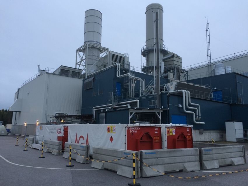

Hydrogen gas as fuel in gas turbines

     ELNA HEIMDAL NILSSON, JENNY LARFELDT, MARTIN ROKKA, VICTOR KARLSSON

                     ISBN 978-91-7673-121-5 | © 2015 ENERGIFORSK
Energiforsk AB | Phone: 08-677 25 30 | E-mail: kontakt@energiforsk.se | www.energiforsk.se
Authors’ foreword
This project started in July 2014 and has been performed by Combustion Physics,
Lund University, Siemens Industrial Turbomachinery AB and Göteborgs Energi.
The governing idea of the project, to go into detail in investigating laminar burning
velocities and the chemistry of laminar flames of natural gas with hydrogen addi-
tion, came up after a succesfull earlier study on a Siemens gas turbine, in a project
financed by SGC (SGC report 2013:256). Götebrogs Energi was involved since
they use Siemens gas turbines for power generation at Ryaverken, Göteborg. Sie-
mens as well as Göteborgs Energi have a strong interest in fuel flexibility in gas
turbines and thus support research related to future fuel mixtures. Combustion
Physics at Lund University has been the academic partner in the project, responsi-
ble for production of the major project results using experimental and computa-
tional facilities in Lund. Siemens have contributed by results from a full scale test
with hydrogen gas at Siemens in Finspång. The project time was 9 month and it
was ended in March 2015.

The reference group following the project has been;
Anna-Karin Jannasch, Energiforsk (project coordinator)
Martin Rokka, Göteborgs Energi
Victor Karlsson, Götebrogs Energi
Jenny Larfeldt, Siemens Industrial Turbomachinery AB
Summary
The project concerns laminar burning velocities of fuel mixtures relevant to gas tur-
bine combustion. Today the main gas turbine fuel is natural gas with methane as
the dominating component and smaller fractions of heavier hydrocarbons. Future
gas turbine fuels will likely include hydrogen gas and biogas with large fractions of
carbon dioxide. In particular hydrogen gas is of interest because it will alter the com-
bustion properties of the gas turbine fuel, broadening the flammability limits and
increase burning velocity.
  Therefore laminar flames of different fuel mixtures were studied at standard con-
ditions, pressure of 1 atm and initial gas mixture temperature of 298 K. Mixtures
were varied in the aspects of natural gas composition, and these different mixtures
were then enriched with hydrogen in varying amounts. Chemical kinetics simulations
were performed for the same conditions, but also for a range of elevated pressures
and temperatures.
  The main conclusion from the experimental study is that addition of hydrogen pro-
mote some fuel mixtures more than others. The strongest effect is seen on pure
methane+air flames, slightly weaker on methane/ethane+air flames, and even
weaker on mixtures incorporating propane. These experimentally determined trends
were supported by the simulations.
  For efficient computations, the chemical kinetics mechanisms need to be as small
as possible, the ones tested in the present study include about 50 species, but a
fast mechanism should ideally have fewer than 20. Smaller mechanisms can be
obtained through a reduction procedure where species are systematically removed
from the larger mechanisms. A method for this was developed and tested within the
project, it was concluded that this method could reduce the mechanism size and
computational time by about one third.
  Among the three kinetics mechanisms tested, the so called San Diego mechanism
was the one that showed to give good results over a wide ranging conditions, and it
is recommended for further use.

2
Sammanfattning
Förbränning i gasturbiner är en viktig del av elproduktionen och med världens
ökade energibehov kommer gasturbinförbränning troligtvis att öka i framtiden. Da-
gens gasturbiner drivs främst på fossil naturgas vars främsta beståndsdel är me-
tan, med mindre andelar av andra kolväten som etan och propan. På senare år
har man kunnat se att sammansättningen av naturgasen har varierat alltmer, både
med avseende på tyngre kolväten och på mindre reaktiva komponenter som kväv-
gas och koldioxid. Dessa variationer leder till variationer i gasens värmevärde och
därmed variation i driften av gasturbinerna. På grund av ökad användning av för-
nybara bränslen är det troligt att man framöver kommer att elda biogas från rötning
samt restgaser från olika industriella processer i befintliga gasturbiner. Detta stäl-
ler krav på flexibilitet i driften av gasturbinerna. En gas som är högaktuell är vät-
gas. Ett intresse finns att öka halten vätgas i naturgasnätet och att lokalt elda stora
andelar vätgas i situationer där tillgången är stor. Siemens har på grund av detta
undersökt hur stor andel vätgas som kan blandas in i deras standardbrännare och
efter en studie inom ett SGC projekt (SGC report 2013:256) kunde man garantera
en inblandning på 15%. Vätgas är en liten gasmolekyl i jämförelse med metan och
de andra kolvätebränslena, den brinner med betydligt högre flamhastighet och är
mer påverkad av diffusion än de andra gaserna. Dessa egenskaper behöver un-
dersökas mer och flammorna behöver testas under laboratorieförhållanden för att
öka förståelsen. Utöver experiment är även simuleringar av flammorna viktiga ef-
tersom det ökar detaljförståelsen samt möjliggör undersökning av förhållanden
som kan vara svårt eller kostsamt att utföra experimentellt.
   Projektet handlar om att studera laminära, endimensionella, laboratorieflammor
av naturgas med olika inblandning av vätgas. På så sätt ökas förståelsen av hur
vätgasinblandning ökar flamhastigheten hos naturgasflammor av olika samman-
sättning. Dessa flammor har i projektet undersökts experimentellt samt med simu-
leringar. Ett viktigt syfte med simuleringarna var att undersöka vilken av flera ke-
miska mekanismer av olika komplexitet som bäst och mest tidseffektivt förutsäger
de experimentella resultaten.
   Naturgasblandningar med olika förhållanden metan:etan:propan undersöktes,
med 0-50% vätgasinblandning. Naturgasblandningarna utan vätgas hade alla ca
samma flamhastighet, något snabbare än ren metan. Inblandning av tyngre kolvä-
ten öka alltså flamhastigheten något. Inblandning av vätgas ökar i alla fallen flam-
hastigheten signifikant, för 10% vätgas ökas flamhastigheterna 2-15% och för 50%
vätgas är ökningen upp till 160%. En tydlig trend är att de största ökningarna sker i
flammor med syreunderskott, moderata ökningar vid syreöverskott, och minst ök-
ning vid stökiometriska förhållanden.
   De undersökta kemiska beräkningsmekanismerna gav alla ganska bra överens-
stämmelse med experimenten, förutom att en av dem överpredikterade alla fall där
propan var med i gasblandningen. Överlag var slutsatsen att den mekanism som
kallas San Diego var den som bäst predikterade flamhastigheter under alla aktu-
ella förhållanden och konklusionen är att denna mekanism ska användas i fram-
tida studier.
   Då biogas med högt koldioxidinnehåll kan vara aktuellt för gasturbinförbränning
undersöktes dessa gasblandningar med hjälp av simuleringar. Koldioxid minskar
flamhastigheter men simuleringarna visar att genom att tillsätta vätgas till dessa

                                                                                     3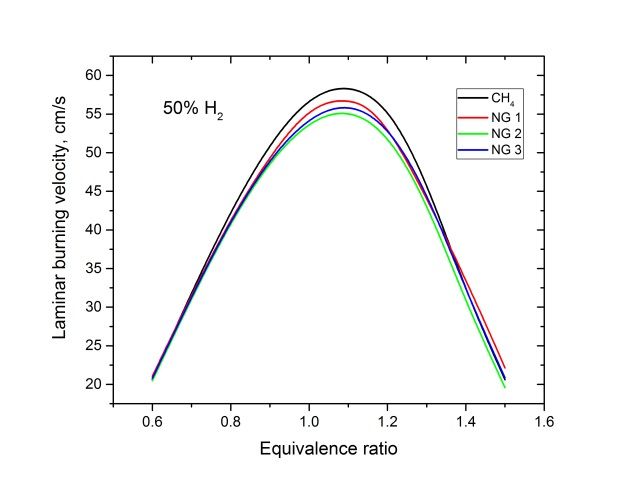
flammor kan flamhastigheten åter ökas och därmed stabiliseras flamman och ger
en mer stabil drift i gasturbinen.
   Som en del av projektet gjordes försök att minska de kemiska mekanismernas
storlek medan deras förmåga att förutsäga flamhastigheter skulle behållas. Det
program som utvecklades för detta minskade en standard naturgasmekanisms
storlek med ca en tredjedel, med en minskning i beräkningstid som var i samma
storleksordning. Slutsatsen från den delen av projektet är att den typen av reduce-
ringar av mekanismstorlek och beräkningstid inte leder till några drastiska minsk-
ningar i beräkningstid.

4
List of content
1.      Background ..................................................................................................... 6
     1.1 Motivation ..................................................................................................... 6
     1.2 Composition of gas turbine fuels................................................................... 6
     1.3 Hydrogen combustion ................................................................................... 7
     1.4 Purpose and aims ......................................................................................... 7
2.      Experimental ................................................................................................... 9
     2.1 Laminar flames ............................................................................................. 9
3.      Results and discussion.................................................................................. 12
     3.1 Experimental laminar burning velocities...................................................... 12
     3.2 Performance of chemical kinetics mechanisms .......................................... 16
     3.3 A tool for generation of reduced mechanisms............................................. 18
4.      Conclusions and outlook ............................................................................... 19
5.      Literature ....................................................................................................... 20
6.      Appendix Siemens´s project contribution ...................................................... 21

                                                                                                                           5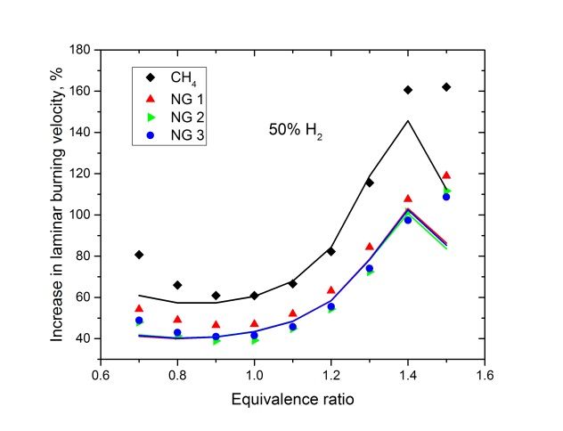
1. Background

1.1 Motivation
Gas turbines are important for power generation and as a result of increasing energy
demand it is likely that their importance will grow in the coming decades. A gas
turbine can run on a range of fuels, but currently the common fuel is natural gas
from fossil fuel sources. For future energy security and environmental concerns
other gases like biogas and hydrogen gas are likely to be used. One clear trend in
demand on power generation systems like gas turbines is the increasing need for
fuel flexibility. This is strongly linked to security of energy supply since the power
production becomes vulnerable if it has to rely on fuel of a certain composition, from
one or a few sources. Systems that can work efficiently for a range of fuel composi-
tions ensure power production less sensitive to political factors.
   In section 1.2 the composition of current gas turbine fuels will be reviewed and
possible composition of future fuels will be outlined. One important gas that can be
produced from renewable energy is hydrogen gas. The hydrogen molecule, H2, is
the smallest existing gaseous fuel component and as a result it has combustion
characteristics that differ from the ones of more common hydrocarbon fuels, as out-
lined in section 1.3. In a previous study a test with a full scale gas turbine was per-
formed and it was found that up to 15 vol% hydrogen can be allowed in Siemens
standard combustion system [1. During that project it was realized that there is poor
data in literature on combustion properties for such mixed gases particularly at rel-
evant gas turbine conditions, this will partly be adressed in the present study. The
purpose and aims of the present project are outlined in section 1.4.

1.2 Composition of gas turbine fuels
The composition of natural gas varies between different sites [2]. The main compo-
nent is methane (CH4) with variations in the range 80 to 99%. Ethane (C2H6) and
propane (C3H8) are the two other main hydrocarbon constituents and can vary from
trace amounts and up to 15% for ethane and 10% for propane. Other compounds
present can be carbon dioxide (CO2) with up to a few percent and nitrogen (N2),
commonly a few percent but up to 10%. The composition of the natural gas will
influence the heating value as well as the combustion characteristics.
  As the national and international gas transportation grids include gas from many
sources there will inevitably be a variation in gas mixture composition and properties
delivered to the customer. It has been reported that the variation has grown in the
US [3], and the same is reported for the Swedish transmission gas grid owner,
Swedegas [4]. Figure 1 presents higher heating values (HHV) for the period 2010
to 2014. 2010-2012 the HHV mostly varied in the range 12.1 to 12.3, and the weekly
variation is seldom more than 0.5. From 2013 the HHV started to vary more, and
mostly to lower values. An extreme case is about a week in December 2014, shown
in the inset in Figure 1, here the HHV ranges from the very low value 11.4 to the
standard value of 12.2. The variations are very fast, with extremes only a few hours
apart.
  Future gas turbine fuels can be of more strongly varying composition compared
the mentioned natural gas mixtures [3]. Raw biogas can for example have a me-
thane content of about 50% and the rest being mainly CO2 and N2, these gases may
need to be upgraded before use. Another possible fuel source is refinery waste gas

6
with high hydrogen gas content, up to 90%, and the same hydrocarbon compounds
as in natural gas. Synthesis gas (syngas) mixtures with varying H2 and CO levels
can also be considered.

Figure 1. Higher heating values for Dragör 2010-2014 [4]. Inset show a zoom of 1-
15 December 2014.

1.3 Hydrogen combustion
Hydrogen gas is highly reactive and therefore has a very high laminar burning ve-
locity. When added to slower burning fuels the hydrogen will extend the flammability
limits and enhance flame propagation. This can result in a more efficient combus-
tion, giving lower emission of hazardous air pollutants and greenhouse gases.
   It has been shown [5] that hydrogen increase the laminar flame speed through
kinetic, thermal and diffusion effects. The kinetic effect is the largest contributor to
flame speed enhancement, while diffusion effects are so small they are considered
negligible [5].

1.4 Purpose and aims
The purpose of the project is to investigate laminar flame speeds of natural gas
mixtures, with particular focus on hydrogen enriched flames. This was done using
experiments where laminar burning velocities were measured, and by numerical
simulations of the flames using several kinetic mechanisms. The performance of the
mechanisms are evaluated using a new set of experimental data on laminar burning
velocities. The understanding gained from experiments and modeling should ulti-
mately result in development of a reduced chemical kinetics mechanism, a smaller

                                                                                      7
and less computationally demanding version of the advanced mechanism. This is-
sue is in the present study approached by development of an automatic reduction
tool for creation of smaller mechanisms from the well-known and reliable detailed
mechanisms.
The project is divided into three main parts, A-C:
A. Modeling of laminar flames of the natural gas components methane, ethane
and propane with air and the same flames with different amounts of hydrogen
gas.
B. Experimental determinations of laminar flame speeds for gas mixtures of the
natural gas components methane, ethane and propane with air and with hy-
drogen gas.
C. Initial experiments of laminar flames at high pressures (up to 25 bar) to ena-
ble evaluation of the possibilities of future experimental studies of these
flames.
Main focus of the present project is laminar flames at standard conditions, mean-
ing an operation pressure of 1 atm and an initial gas mixture temperature of 298 K.
The gas mixtures given in Table 1 were all investigated using flame simulations and
the first four mixtures were measured experimentally. In addition several mixtures
were simulated also at elevated temperatures and pressures to investigate the per-
formance of the mechanisms and increase the understanding of the chemistry be-
hind.
The particular choice of gas mixture compositions are based on several consider-
ations. For the natural gas (NG) mixtures comparably high concentrations of ethane
and propane were chosen, on the upper limit for what can be present in real natural
gas. In a comparative study of several components with similar characteristics it is
important to investigate these extreme cases since it is important to identify differ-
ences that are large enough to be outside the error bars of the measurements. An-
other motivation is that all these mixtures, with the exception of NG 3, have to some
extent been investigated previously, which enable a verification of the quality of the
experimental data by comparison with other experimental datasets at some condi-
tions.
Table 1. Composition of the gas mixture used in experiments and simulations.
CH4 C2H6 C3H8 CO2
CH4 1
NG 1 0.8 0.2
NG 2 0.8 0.2
NG 3 0.8 0.1 0.1
BG 1 0.8 0.2
BG 2 0.6 0.4
82. Experimental
2.1 Laminar flames
Laminar flames of the fuel mixtures given in Table 1 were experimentally investi-
gated using the heat flux method, section 2.1.1, and simulations, section 2.1.2.
2.1.1 Heat flux experiments
The heat flux method for determination of laminar burning velocities is a method
where the property is determined directly in a stretch free flame under adiabatic
conditions [6]. A schematic of the experimental setup is presented in Figure 2, show-
ing the mixing panel for setting the gas mixture composition, and the burner with
water baths controlling the temperature of the unburnt gas mixture and of the burner
plate.
Figure 2. Schematic of the Heat Flux setup used in the present work.
9A one dimensional flame, see Figure 3, is stabilized on a perforated plate burner heated to a temperature at least 20 K above the temperature of the combustible gas mixture. Heat transfer between the flame and the burner head is at adiabatic condi- tions equal in both directions, which means there is no net heat transfer. At these conditions the temperature of the burner plate is uniform. By varying the flow of gas while monitoring the temperature profile, measured by eight thermocouples in the burner plate, the adiabatic laminar burning velocity is found. Figure 3. A 1D flame stabilized on a heat flux burner. The combustible mixture of fuel and oxidizer is created using a mixing panel with gas Mass Flow Controllers (MFCs). All these components are from Bronkhorst. The gas MFCs are regularly calibrated for air, using a piston meter, Definer from Bios. The setup used for the present experiments has been described previously [7]. Un- certainties in gas mixture composition and laminar burning velocity were assessed, as previously described [8]. Typical uncertainties are ±1 cm s-1 for laminar burning velocity and ±0.01 in equivalence ratio. Experiments were performed at 1 atm pressure, initial gas mixture temperatures of 298 K and φ in the range 0.7-1.5. The temperature of the burner head was kept constant at 368 K. The three natural gas component mixtures NG 1, NG 2 and NG 3, were bought in premixed bottles from AGA. 2.1.2 Chemical kinetics modeling Modeling of laminar flames was performed using the CHEMKIN software for com- bustion simulations [9]. Three different chemical kinetics mechanisms were used, for their main characteristics see Table 2. San Diego [10] is today regarded as the most versatile and reliable natural gas mechanism, it is continuously improved and developed to cover wider range of conditions. GRI3.0 [11] is widely used, it is no longer being updated and has shown to have some flaws compared to the more up to date San Diego, but due to its wide use and fast calculations it is still considered an important mechanism for natural gas applications. The mechanism of Wang et al. [12] is recently developed and has not yet been used very much. 10
Table 2. Three detailed mechanisms used in the present study. “#species” and
“#reactions” refer to the number of unique molecular species and number of re-
versible reactions involving these species, for each mechanism. The fourth column
gives the time for computing the laminar burning velocity at φ=1.1, at standard
conditions using CHEMKIN with the same set of initial parameters for all three
mechanisms.
 Mechanism         # species       # reactions      Time (s)         Reference
 San Diego         40              180              55               [10]
 GRI3.0            53              325              45               [11]
 Wang et al.       56              428              63               [12]

                                                                               11
3. Results and discussion 3.1 Experimental laminar burning velocities Laminar burning velocities at standard conditions were determined for methane+air flames and for the three natural gas mixtures NG 1, NG 2 and NG 3 defined in Table 1. The four mixtures were also mixed with hydrogen gas, 10, 35 and 50%. Finally a higher hydrogen gas mixture of 65% was approached, but due to acoustic instabili- ties the experiments were terminated until possible safety issues related to burning these high hydrogen mixtures have been investigated. Figures 4 and 5 present laminar burning velocities of methane and NG 1 and NG 2, together with literature data [13, 14] for the same mixture compositions. For the case of methane, Figure 4, the agreement with literature is good at the lean side, while the study by Bosschaart et al. [13] give higher values at the rich side. In that study the same experimental method was used as in the present study. The method has been improved, in particular with respect to calibration of mass flow controllers to yield correct gas mixture composition, therefore it is likely that the present dataset is more accurate. For natural gas mixtures presented in Figure 5 the literature data are higher at rich side and lower at lean side, it looks like a shift in data, possibly as a result of larger uncertainties in gas mixture composition in the earlier study. Figure 4. Laminar burning velocities of methane determined in the present study, together with literature data. 12
Figure 5. Laminar burning velocities of methane/ethane and methane/propane
mixtures determined in the present study, together with literature data.
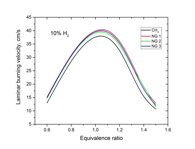
Figures 6-9 present experimental results for all investigated mixtures. Figure 6
shows mixtures with air, the laminar burning velocity for methane is slightly lower
than the others. The three mixtures with 80% methane and different proportions of
ethane and propane all have similar laminar burning velocities. Figures 7-9 show
the same mixtures with hydrogen gas enrichment of 10, 35 and 50%. As expected
an increased amount of hydrogen leads to an increase in laminar burning velocity.
The interesting trend here is that hydrogen seems to promote methane more than
the other gas mixtures, and ethane more than propane. Methane that was the slow-
est burning one without hydrogen becomes the fastest at hydrogen content of 50 %,
while the propane containing mixtures NG 2 and NG 3 burn significantly slower than
the ones with no propane.
13Figure 6. Experimental results of laminar burning velocities for pure methane+air flames and the three mixtures with 20% ethane and/or propane. Figure 7. Experimental results of laminar burning velocities for pure methane+air flames and the three mixtures with 20% ethane and/or propane, enriched with 10% H2. 14
Figure 8. Experimental results of laminar burning velocities for pure methane+air
flames and the three mixtures with 20% ethane and/or propane, enriched with
35% H2.
Figure 9. Experimental results of laminar burning velocities for pure methane+air
flames and the three mixtures with 20% ethane and/or propane, enriched with 50%
H2.
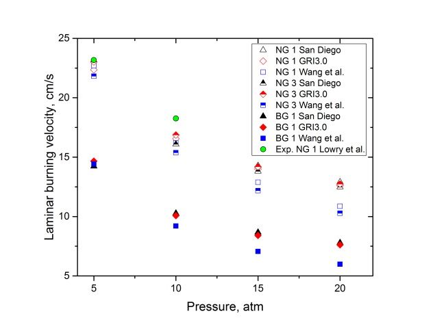
15As evident from above hydrogen gas promotes the natural gas flames differently depending on the hydrocarbon composition. This is further presented in Figure 10 where the increase in laminar burning velocity upon hydrogen enrichment, com- pared to flames without hydrogen, are plotted as a function of equivalence ratio for the four mixtures. In the first panel, 10% hydrogen gas, the increase in laminar burn- ing velocity is modest, in the range 2 to 20% with stronger promotion at rich condi- tions. For methane/hydrogen mixture the data point for stoichiometric conditions for 10% mixture seem to be an outlier. Upon examination of the experimental data it is concluded that this is likely as a result of a deviating measurement of the mixture with hydrogen, since this particular datapoint are higher than the general trend showing in Figure 7. The second panel shows an increase of up to 160% for me- thane. An interesting result when comparing the two figures is that at 10% hydrogen, methane and NG 1 are similarly promoted by hydrogen gas, while at 50% hydrogen, methane is more strongly affected. The full drawn lines, from simulations using the San Diego [10] mechanism, are further discussed in the next section. Figure 10. The effect of H2 on the laminar flame speed of the different fuel mix- tures represented by plots of the increase in percent. Lines in figures are modeling using the San Diego mechanims [10], with color coding the same as for the experi- ments. 3.2 Performance of chemical kinetics mechanisms The three investigated mechanisms are of similar complexity and performance. As seen in Table 2 the GRI3.0 mech is the least time consuming one for computation of a methane+air flame at a given set of conditions, but a significant drawback of this mechanisms is that it overpredicts the laminar burning velocity of all natural gas mixtures containing propane, in the present case NG 2 and NG 3, respectively. In Figure 11 the performance of the three mechanisms with pressure and temperature is shown. San Diego is generally considered to be the best natural gas mechanism and compared to this one the Wang et al. mechanism give to low laminar burning velocities with increasing divergence as pressure increase. GRI3.0 is in agreement with San Diego for NG 1 and BG 1, but not for the propane containing NG 3. Figure 10 above shows a comparison of results from modeling using San Diego [10] to the comparison of increase in laminar burning velocity as a result of hydrogen addition. The simulations capture the experimental trend that the methane laminar burning velocity is more enhanced compared to the NG mixtures. It fails to separate 16
the effects of ethane and propane, all three NG mixtures should according to simu-
lations be equally promoted by hydrogen addition. For all cases the simulations pre-
dict that at an equivalence ratio of 1.5 the enhancement due to hydrogen should
again decrease, while the experimental data at this point for most cases show a
levelling out behaviour, but no decrease. The simulated results are closer to the
experimental data for the 50% hydrogen case, which indicate that the mechanism
has an accurate chemical description of hydrogen, but possibly some minor flaws
concerning hydrocarbon combustion. This conclusion is based upon the fact that
the chemistry at 10% hydrogen content is still largely hydrocarbon dominated.
Figure 11. Laminar burning velocities of fuel mixtures NG 1, NG 3 and BG 1, simu-
lated using three mechanisms [10-12]. The left hand side panel show the depend-
ence of pressure and the right hand side the temperature. For pressure dependence
two experimental data points from Lowry et al. [14] are also included.
Figure 12 is the simulated (San Diego) counterpart to the experimental data pre-
sented in Figures 7 and 9. The trend is similar to the experiments, with methane
being more strongly promoted than the natural gas mixtures as the hydrogen frac-
tion increases.
Figure 12. Simulated laminar burning velocities for methane and natural gas mix-
tures, with 10% (left) and 50% (right) of hydrogen gas.
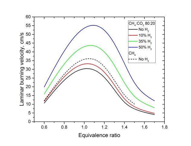
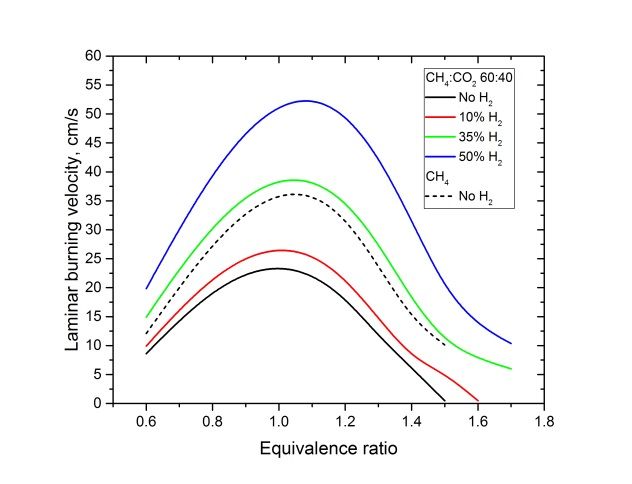
The Wang et al. mechanism was used to compare biogas mixtures with 20 and 40%
CO2, and investigate how they respond to hydrogen enrichment. In Figure 13 it is
17seen that the biogas mixtures burn significantly slower than pure methane. Addition of hydrogen can compensate for this flame retardation, in the case of the higher CO2 fraction, 40%, it can be seen in the panel to the right that 35% hydrogen enrichment approximately compensate and bring the laminar burning velocity back to that of a pure methane flame. Figure 13. Simulated (Wang et al.) laminar burning velocities for BG 1 and BG 2, and the mixture of those with hydrogen gas. 3.3 A tool for generation of reduced mechanisms Smaller kinetic mechanisms can be generated from the above investigated ad- vanced mechanisms. In the present work a reduction tool was developed. The pro- gram builds on removal of unimportant species and the reaction these species take part in. The target for the reduced mechanisms is set in the program, most com- monly it was chosen to produce laminar burning velocities within a few percent of the results from the advanced mechanism. Species that are known to be of im- portance are marked not to be removed and then the program iterate through the rest of the species, testing if the mechanism still reproduce the target results after removal of species. When tested on the GRI3.0 mechanism for methane+air flames the reduced mechanism had 42 species and 266 reactions, before the results was outside the given limits. This gave a time reduction of a third for the test case, 30 s instead of the 45 s for the full GRI3.0. From this, it became obvious that a truly reduced mechanism of in the range 10- 20 species can hardly be produced from an advanced mechanism using automatic reduction. A further reduction requires modification of the true reaction rate con- stants, to lump several reactions into an overall reaction representing several reac- tion steps. 18
4. Conclusions and outlook
The most important outcome of the experimental laminar flame study is that hydro-
gen enrichment promotes the hydrocarbon mixtures differently. Pure methane is
more strongly promoted than the ones containing ethane and propane. The practical
use of this knowledge is that in a situation where hydrogen gas is added to a natural
gas fuel, the strength of the flame promoting effect depends on the composition of
the natural gas mixture. A larger amount of heavier hydrocarbons will to some extent
inhibit the flame promoting effect of hydrogen gas.
   The investigation of three chemical kinetics mechanisms for natural gas combus-
tion reveal that they have about the same performance, but GRI3.0 fail for propane
containing flames and Wang et al. mechanism diverge from the others at high pres-
sures. The trends seen in the experiments, regarding stronger promotion of me-
thane flames, is supported by the simulations, which indicate that they are indeed
representing the chemistry correctly at standard conditions.
   For simulations of biogas mixtures it is concluded that hydrogen gas can compen-
sate for the decreased reactivity resulting from the CO2 content. Balancing CO2 con-
tent in biogas or natural gas with H2 to get ideal flame properties might be a way to
compensate for CO2 contaminated fuels. This will allow the fuels to be burnt directly,
instead of first using a CO2 removing process.
   Regarding mechanism reduction it is concluded that the tool developed in the pre-
sent project does not manage in large reduction of mechanisms. It is able to cut the
computational time by about one third, still keeping satisfying performance.
   The present study will be a stepping stone to further work concerning understand-
ing of effects of hydrogen gas on hydrocarbon flames. An important continuation is
the determination of flame properties at pressures relevant to gas turbine combus-
tion. It has been shown that a high pressure burner [13] for laminar flame studies
are suitable for studies related to this. Experimental data at high pressures will en-
able further validation of kinetic mechanisms and identification of parameters of im-
portance.

                                                                                   19
5. Literature
1. Andersson M.; Larfeldt J.; Larsson A., “Co-firing with hydrogen in industrial
gas turbines”, SGC 256, 2013.
http://www.sgc.se/ckfinder/userfiles/files/SGC256(1).pdf
2. Kakaee, A. H.; Paykani, A.; Ghajar, M., The influence of fuel composition
on the combustion and emission characteristics of natural gas fueled en-
gines. Renew. Sust. Energ. Rev. 2014, 38, 64-78.
3. Richards, G. A.; McMillian, M. M.; Gemmen, R. S.; Rogers, W. A.; Cully, S.
R., Issues for low-emission, fuel-flexible power systems. Prog. Energy
Combust. Sci. 2001, 27 (2), 141-169.
4. Swedegas, Göteborg. www.swedegas.se
5. Tang, C. L.; Huang, Z. H.; Law, C. K., Determination, correlation, and
mechanistic interpretation of effects of hydrogen addition on laminar flame
speeds of hydrocarbon-air mixtures. Proceedings of the Combustion Insti-
tute 2011, 33, 921-928.
6. Vanmaaren, A.; Degoey, L. P. H., STRETCH AND THE ADIABATIC BURN-
ING VELOCITY OF METHANE-AIR AND PROPANE-AIR FLAMES. Com-
bustion Science and Technology 1994, 102 (1-6), 309-314.
7. Naucler, J. D.; Christensen, M.; Nilsson, E. J. K.; Konnov, A. A., Oxy-fuel
Combustion of Ethanol in Premixed Flames. Energy & Fuels 2012, 26 (7).
8. Naucler, J. D.; Sileghem, L.; Nilsson, E. J. K.; Verhelst, S.; Konnov, A. A.,
Performance of methanol kinetic mechanisms at oxy-fuel conditions. Com-
bustion and Flame (2015) In press..
9. CHEMKIN IV 15101, Reaction Design: San Diego (2010)
10. San Diego mechanism web page
http://web.eng.ucsd.edu/mae/groups/combustion/mechanism.html, 2012,
“Chemical-Kinetic Mechanisms for Combustion Applications”. Mechanical
and Aerospace Engineering (Combustion Research), University of Califor-
nia at San Diego.
11. Frenklach F., Wang H., Yu C.L., Goldenberg M., Bowman C.T., Hanson
R.K., Davidson D.F., Chang E.J., Smith G.P., Golden D.M., Gardiner W.C.
& Lissianski V.; http://www.me.berkeley.edu/gri_mech.
12. Wang, Q. D., Skeletal Mechanism Generation for High-Temperature Com-
bustion of H-2/CO/C-1-C-4 Hydrocarbons. Energy & Fuels 2013, 27 (7),
4021-4030.
13. Bosschaart, K. J.; de Goey, L. P. H., The laminar burning velocity of flames
propagating in mixtures of hydrocarbons and air measured with the heat
flux method. Combustion and Flame 2004, 136 (3), 261-269.
14. Lowry, W.; de Vries, J.; Krejci, M.; Petersen, E.; Serinyel, Z.; Metcalfe, W.;
Curran, H.; Bourque, G., Laminar Flame Speed Measurements and Model-
ing of Pure Alkanes and Alkane Blends at Elevated Pressures. Journal of
Engineering for Gas Turbines and Power-Transactions of the Asme 2011,
133 (9).
15. Joo, P; Li, Z; Aldén, M, Design of high pressure experimental apparatus
with optical access for combustion experiments. Book of abstracts for Joint
meeting of The British and Scandinavian-Nordic Sections of the Combus-
tion Institute, Cambridge OK, 2014
206. Appendix Siemens´s project contribution
With the purpose to find the maximum concentration of hydrogen in natural gas that Sie-
mens gas turbines SGT-700 and SGT-800 can handle with standard combustion system a
test was performed in 2012 [A1]. During that test the system was operated with up to 40 %
by volume of H2, and it was investigated how the flame position change as a result of in-
creasing hydrogen content. The understanding developed during the test resulted in that
Siemens today offers the standard SGT-700 and SGT-800 with up to 15 % by volume of
H2. Siemens has continued the development effort to enable operation on higher hydrogen
contents.
To achieve stable operation at higher hydrogen content a slightly modified burner was de-
veloped. The burner was installed into a full scale gas turbine and tested in October 2014.
The test set up described in [A1] was used, but with larger quantity of hydrogen. The hy-
drogen storage at the fuel feeding facility is shown in Figure A1.
The tests were performed for a range of hydrogen fractions in the fuel, and for various gas
turbine loads. A wide range of test conditions is important to ensure stable operation. The
test proved the capability of the concept burner to operate with at least 45 % by volume hy-
drogen in natural gas. It was also concluded that the NOx emissions could be kept below
24 ppm@15 % O2 at 70-100 % gas turbine load with the hydrogen rich fuel. Normal opera-
tion including transients and load cycling was also demonstrated with the hydrogen rich
fuel.
Figure A1. Siemens delivery test beds in Finspång during test with hydrogen co-firing
3rd to 8th of October 2014.
21The burner design showed to be suitable for long term operation with high hydrogen fuels since material temperatures, for instance at the burner tip, were acceptable and sometimes even lower than for the standard burner. Work is in progress at Siemens to realize the concept burner in a gas turbine product that can be offered to the market in near future. References A1 Andersson, Larfeldt and Larsson, “Co-firing with hydrogen in industrial gas turbines”, SGC Rapport 2013:256 22
HYDROGEN GAS AS FUEL IN GAS
                                  TURBINES
                                  Intresset för gasturbiner för kraftgenerering ökar. Inte minst för att möta det
                                  växande behovet av reservkraft i takt med att den förnybara elproduktionen
                                  byggs ut i Europa. Idag drivs gasturbinerna mestadels med fossil naturgas, men
                                  allt oftare efterfrågas möjligheten att också kunna driva turbinerna med andra
                                  energigaser såsom förnybar vätgas, biogas samt blandningar av dessa. Man ser
                                  också ett ökat behov av att kunna hantera en kontinuerlig drift med en med
                                  tiden varierande gaskvalité. För att kunna anpassa och säkerhetsställa driften
                                  för dessa nya villkor krävs en ökad förståelse för hur olika gaskomponenter på-
                                  verkar förbränningsförloppen i turbinen. I den här studien har man studerat
                                  inverkan av vätgasinblandning i naturgas och biogas av olika sammansättning.

Another step forward in Swedish energy research
Energiforsk – Swedish Energy Research Centre is a research and knowledge based organization that
brings together large parts of Swedish research and development on energy. The goal is to increase the ef-
ficiency and implementation of scientific results to meet future challenges in the energy sector. We work
in a number of research areas such as hydropower, energy gases and liquid automotive fuels, fuel based
combined heat and power generation, and energy management in the forest industry. Our mission also
includes the generation of knowledge about resource-efficient sourcing of energy in an overall perspecti-
ve, via its transformation and transmission to its end-use. Read more: www.energiforsk.se
You can also read