Influence of laser-directed energy deposition process parameters and thermal post-treatments on Nb-rich secondary phases in single-track Alloy ...
←
→
Page content transcription
If your browser does not render page correctly, please read the page content below
Influence of laser-directed energy deposition
process parameters and thermal post-
treatments on Nb-rich secondary phases in
single-track Alloy 718 specimens
Cite as: J. Laser Appl. 33, 022024 (2021); https://doi.org/10.2351/7.0000259
Submitted: 08 October 2020 . Accepted: 30 April 2021 . Published Online: 18 May 2021

  Suhas Sreekanth,      Kjell Hurtig,   Shrikant Joshi, and      Joel Andersson

J. Laser Appl. 33, 022024 (2021); https://doi.org/10.2351/7.0000259                    33, 022024

© 2021 Author(s).
Journal of                                                                                       ARTICLE            scitation.org/journal/jla
 Laser Applications

    Influence of laser-directed energy deposition
    process parameters and thermal post-treatments
    on Nb-rich secondary phases in single-track Alloy
    718 specimens
    Cite as: J. Laser Appl. 33, 022024 (2021); doi: 10.2351/7.0000259
    Submitted: 8 October 2020 · Accepted: 30 April 2021 ·                                                                View Online   Export Citation    CrossMark
    Published Online: 18 May 2021

    Suhas Sreekanth,a)              Kjell Hurtig,          Shrikant Joshi,   and Joel Andersson

    AFFILIATIONS
    Department of Engineering Science, University West, 461 86 Trollhättan, Sweden

    a)
      Author to whom correspondence should be addressed; electronic mail: suhas.sreekanth@hv.se. Telephone: +46-520-223-484

    ABSTRACT
    In this article, process parameters such as laser power, deposition speed, and powder feed rate are varied at three levels, and their effect on
    geometrical characteristics and microstructural features of laser-direct energy deposited single-track Alloy 718 specimens is analyzed.
    Furthermore, the influence of standard heat treatments recommended for wrought form of Alloy 718 is investigated on as-built deposits.
    The main aim of the research is to curtail the amount of secondary Nb-rich precipitates such as Laves and NbCs either during the process
    or by subsequent heat treatments. The volume fraction analysis of Nb-rich phases shows that processing at high laser power conditions is
    ideal for minimizing segregation. Upon subjecting as-built deposits to (i) solution treatment, (ii) solution treatment and aging, and (iii)
    direct aging, a difference in volume fraction of Nb-rich phases is noticed compared to the as-built condition. Characterization of size, mor-
    phology, phase constitution through volume fraction estimation, and elemental concentrations employing electron dispersive spectroscopy
    analysis indicates dissolution of Nb-rich phases when subjected to heat treatments. The delta phase precipitation preferentially occurs in the
    top and bottom regions and sparsely in the middle region of the specimens subjected to solution heat treatment. In case of specimens sub-
    jected to direct aging (718 °C/8 h and 621 °C/8 h), delta phase is not discernable, indicating that a higher temperature (>900 °C) treatment
    may be necessary for delta precipitation and growth.

    Key words: directed energy deposition, Alloy 718, process parameters, heat treatment, Nb-rich phases

    © 2021 Author(s). All article content, except where otherwise noted, is licensed under a Creative Commons Attribution (CC BY) license
    (http://creativecommons.org/licenses/by/4.0/). https://doi.org/10.2351/7.0000259

    I. INTRODUCTION                                                             aero-engines,2 and L-DED processing of parts utilizing this superal-
          Additive manufacturing (AM) of metallic material represents           loy has attracted major interest.
    one of the most significant disruptive technologies since the turn of             Alloy 718 is an Ni-Cr-Fe-Nb material system strengthened
    20th century, enabling near-net-shape manufacturing of complex              mainly due to precipitation hardening provided by gamma double
    geometrical structures by bottom-up approach and thereby mini-              prime (γ00 ) and gamma prime (γ0 ) phases. However, long term
    mizing the need for machining.1 Laser-directed energy deposition            stability of the alloy at high temperatures is also influenced by con-
    (L-DED) is one of the main subgroups of the metal-AM process                trolled precipitation of the delta (δ) phase at the grain boundaries
    that offers solution in production of components, part features,            (GBs) as propounded by Barker et al.3 Gleeble simulation studies
    prototyping, and repair applications. The process can be used in a          in the solution treatment temperature range of Alloy 718 (954–
    diverse range of applications and is considered a particularly attrac-      1050 °C) have shown that the δ phase in low proportions is benefi-
    tive option in the aerospace industry. Alloy 718 is one of the mate-        cial for providing structural stability by inhibiting grain growth, as
    rials most widely considered for hot structural components in               per the research conducted by Andersson et al.4 Based on the

J. Laser Appl. 33, 022024 (2021); doi: 10.2351/7.0000259                                                                                                 33, 022024-1
© Author(s) 2021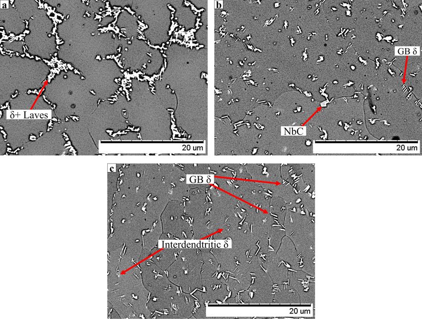
Journal of                                                                                       ARTICLE              scitation.org/journal/jla
 Laser Applications

    processing conditions of Alloy 718, varied amounts of undesirable         temperatures in the range of 900–980 °C for up to 2 h.19
    Laves phase are precipitated with A2B stoichiometry, where Ni, Fe,        Treatments at this temperature range are reported to effect dissolu-
    or Cr elements preferably occupy the “A”-site and Nb, Mo, or Ti           tion of Laves phase present and precipitate controlled amounts of
    elements occupy “B,” as discussed by Antonov et al.5 The brittle-         δ-phase.20 Therefore, the present work considers a solution treat-
    ness of the Laves phase formed at GBs aid crack propagation,              ment temperature of 954 °C as per the standard specification for
    thereby adversely impacting the strength of the alloy. Sivaprasad         the heat treatment of wrought Alloy 718. The two-step aging is per-
    and Raman6 showed that the increased amount of Laves phase led            formed at 718 and 621 °C for nucleation and growth of γ00 and γ0
    to decreased tensile strength in tungsten arc welded specimens of         precipitates and the growth of δ-phase precipitates.21
    Alloy 718 compared to electron beam welded structures. Schirra                 In summary, the present research considers a unique process
    et al.7 showed that the increased amount of Laves phase in cast and       window involving high feed-rate deposition of single-track Alloy
    wrought forms of Alloy 718 yielded lower room temperature tensile         718 specimens via low heat input, which is advantageous in modi-
    strength and ductility, and elevated temperature fatigue life.            fying the microstructure of the builds. The precipitation kinetics of
    Moreover, since the Laves phase has lower solvus temperature com-         Nb-rich phases in Alloy 718 are process dependent and such
    pared to the matrix, it is often reported to liquate when the alloy       studies are sparsely reported for high feed-rate L-DED, which pro-
    processing steps involve thermal cycling, typical of multipass            vides invaluable data for researchers working with modeling of
    welding and AM processes,8 increasing the cracking susceptibility         process-microstructure relationship. The article provides a detailed
    of the alloy. The much-needed Nb for precipitation of strengthen-         analysis of Nb-rich precipitation under different processing condi-
    ing phases is also pinned down by Laves and NbC, affecting the            tions, which is imperative for the selection of process parameters
    total volume fraction (Vf ) of the γ00 phase and hence the overall        for 3D deposition of Alloy 718. Furthermore, the effects of heat
    strength of the alloy.9 Thus, the segregation behavior of Nb-rich         treatment on precipitation and dissolution mechanisms are studied
    secondary phases and their influence on material properties outline       to verify the suitability of the investigated treatment schedules for
    the need for minimization of such phases. The present research            L-DED applications upon 3D building.
    explores the possibility to minimize Nb-rich phases by variation of
    process parameters and through standard heat treatments, typically
    implemented for laser welded structures.                                  II. MATERIALS AND METHODS
          The key process parameters associated with L-DED primarily          A. L-DED equipment
    involves factors associated with a laser source, beam modification,
                                                                                    The deposition system comprised of an ytterbium-doped fiber
    and powder characteristics. The research thus far has largely
                                                                              laser (wavelength λ ∼ 1070 nm) with a capability of continuous-wave
    focused on process window estimation and optimization of geome-
                                                                              mode operation at 6 kW. The delivery optics had a fiber diameter of
    try, microstructure, solidification and controlled precipitation,
                                                                              800 μm (numerical aperture = 0.2) and consisted of a collimator lens
    defect formation, or surface integrity. Pinkerton10 surveyed progress
                                                                              and a focusing lens of focal lengths 160 and 200 mm, respectively. A
    in modeling L-DED process and pointed that parameters such as
                                                                              screw-type volumetric feeder was utilized for powder feed control.
    laser power, deposition speed, feed rate, and beam diameter are of
                                                                              Argon was used as the shielding and carrier gas. The laser system
    primary importance. Three of these parameters with the exception
                                                                              coupled with the powder feeder and gas feeder systems collectively
    of beam diameter are considered in the present study. However, the
                                                                              formed the deposition head that was mounted on an overhead
    beam diameter has been found to be effective in influencing the
                                                                              gantry system. A stationary workbench supported the substrate plate
    width of deposits and powder capture efficiency.11 A distinctive
                                                                              upon which the deposition process was carried out. Figure 1(a)
    feature of this study is the consideration of high feed rates (0.8–
    1.2 kg/h) compared to many prior L-DED research, where the
    typical feed rate has been varied between 0.3 and 0.6 kg/h.12–14 A
    relatively low heat input (50–100 J/mm), which is typically used for
    processing at 0.6 kg/h powder feed rate in L-DED research identi-
    fied by Dass and Moridi,15 is utilized for high throughput process-
    ing in the present study. Low heat input is found to increase
    cooling rates in low feed-rate conditions16 but has been previously
    reported to affect the homogeneity of the single-track deposits in
    high feed-rate conditions due to varied cooling rates that exist in
    different regions of a deposit.11 The cause of this inhomogeneity
    is dependence of precipitation kinetics on cooling rates that result
    in varied amounts of Nb-rich Laves phase during the processing of
    Alloy 718. These Laves phase precipitates can be dissolved by
    homogenization treatment, which is sparsely utilized for L-DED
    applications, as typical homogenization temperatures exceed
    1050 °C, resulting in grain growth that can negatively influence
    fatigue strength,17 weldability,4 and rupture-ductility18 of Alloy 718.
                                                                               FIG. 1. (a) Arrangement of L-DED system used in the experimental trials. (b)
    Aerospace applications require components having high-strength,
                                                                               The picture of a coaxial COAX-50 nozzle used for deposition.
    which necessitates the processing of Alloy 718 at solution treatment

J. Laser Appl. 33, 022024 (2021); doi: 10.2351/7.0000259                                                                                            33, 022024-2
© Author(s) 2021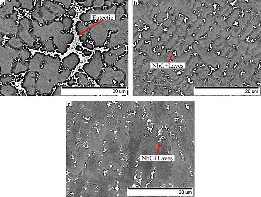
Journal of                                                                                                    ARTICLE                scitation.org/journal/jla
 Laser Applications

    TABLE I. Nominal chemical composition (wt. %) of plasma atomized alloy 718 powder and wrought substrate plate.

    Elements                 Ni                  Cr                   Fe               Nb + Ta                Mo                 C                 Ti                  Al
    Powder                  52.89              18.7                18.52                  4.9                 2.94              0.05             0.92                0.61
    Substrate               53.57              18.7                17.58                  4.97                2.89              0.04             0.91                0.59
    Elements                 Co                  Ta                   B                   Cu                  Mn                 Si                 P                   S
    Powder                   0.11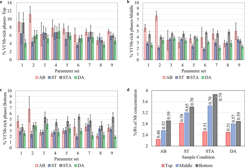
Journal of                                                                                                  ARTICLE             scitation.org/journal/jla
 Laser Applications

                                                                                         Solution treatment: 954 °C/1 h—air cooled
                                                                                         Aging treatment: 718 °C/8 h—furnace cooled at 56 °C/h to 621 °C
                                                                                           + 621 °C/8 h—air cooled to room temperature.
                                                                                               The specimens were analyzed in three different conditions in
                                                                                         order to evaluate the effect of heat treatment, namely, (a) solution-
                                                                                         treated condition (ST), (b) solution-treated + aged conditions
                                                                                         (STA), and (c) direct aged condition (DA).

                                                                                         F. Hardness testing
                                                                                               Micro-Vickers hardness (HV) testing was performed on all
                                                                                         AB and heat-treated samples at a load of 1.96 N (0.2 kg f ) held for
                                                                                         a test time of 15 s. Five indents were made in different regions (top,
                                                                                         middle. and bottom as depicted in Fig. 3) of the track to obtain
                                                                                         representative HV values. As the deposit area available indentation
                                                                                         was very small, the load applied was calibrated to avert indentation
      FIG. 3. A typical transverse cross section of a single-track deposit showing       size effects.23
      height, width, and depth. The top, middle, and bottom regions indicate areas of
      varied microstructural morphologies (see Sec. III B).
                                                                                         III. RESULTS
                                                                                         A. Geometry
    present in the top, middle, and bottom regions as shown in Fig. 3,                         The measured dimensions of height varied between 740 and
    which are further elaborated in Sec. III B. IMAGEJ version 1.52p was                 1230 μm, width varied between 1855 and 2315 μm, and depth
    used for the analysis of micrographs, analyzing substructures, and                   varied between 550 and 1195 μm as shown in Figs. 4(a)–4(c),
    estimation of volumetric content (%Vf ) of different phases in the                   respectively. Figure 4(d) represents the effect plot that determines
    deposits. A minimum of ten micrographs was considered in each                        the impact of each process parameter on the measured dimensions
    region of one single-track deposit for the measurement of %Vf.                       arranged in order from left to right (represented by green bars)
    Based on the brightness-contrast of different constituents discerned                 and the 95% confidence interval is represented by the error bars.
    in the micrographs, a threshold value was assigned to render binary                  For instance, the left-most effects show that the height of a deposit
    images for estimation of Vf of Nb-rich phases. The grain size mea-                   is influenced by speed, feed rate, and power in that order. If the
    surements were performed in accordance with ASTM E112-13                             speed is increased from 700 to 1100 mm/min (low level to high
    standard specification for nonuniform grains.22                                      level), then height decreases by 285 μm as indicated by the green
         Umetrics MODDE-PRO V.12 was used for analysis of experimen-                     bar. During this increase in speed, power and feed rates are main-
    tal design. Partial least squares (PLS) regression method was                        tained at the mid-level which are 1600 W and 16.67 g/min, respec-
    chosen for analyses of responses given the ability of PLS to handle                  tively. Similarly, if the feed rate increases from 13.3 to 20 g/min at
    multiple sets of data with covariances. The regression coefficients                  average values of power (1600 W) and speed (900 mm/min), then
    of responses were plotted in the form of effects plot, which deter-                  the increase in height of 240 μm can be expected. On the other
    mined the variation of height, width, and depth (responses) with                     hand, the effect of variation in power results in a relatively less sig-
    respect to individual factors and arranged in the descending order                   nificant variation in height of 45 μm. Hence, speed and feed rate
    of effect. Based on the effect of process parameters on responses,                   are considered significant factors compared to power in determin-
    combined factors were determined in terms of line mass (Lm) and                      ing of height. The value of height in the present experiments can
    linear heat input (HI) as described by Eqs. (1) and (2),                             be correlated to the ratio of Ṁ /V or line mass, similar to the con-
                                                                                         clusions of de Oliveira et al.24
                                       _
                           Line mass ¼ M/V, in g/mm,                               (1)         The width and depth are significantly affected by power, whereas
                                                                                         speed and feed rate are termed as statistically insignificant variables
                            Heat input ¼ P/V, in J/mm:                             (2)   due to their minor influence. However, a good fit was verified through
                                                                                         the R2 value when P/(V × Ṁ )0.5 was considered as a lumped variable.
                                                                                         P/(V × Ṁ )0.5 can be otherwise expressed as HI/Lm0.5 as seen in
                                                                                         Figs. 4(b) and 4(c). The previously mentioned research by de Oliveira
    E. Heat treatment                                                                    et al.24 states that widths and depths are correlated to P/V0.5 as per the
         The single-track deposits in the as-built (AB) condition were                   theoretical and modeling studies. In a study by Kistler et al.,25 bead
    subjected to a standard heat treatment in accordance with                            widths are correlated to normalized enthalpy (H*), which is the ratio
    AMS5663 N.21 The treatments were performed in two stages as                          of change in enthalpy to enthalpy of melting of a material (hs). It
    shown below and were carried out in a tube furnace with Ar atmo-                     combines material factors such as surface absorptivity (η), density (ρ),
    sphere (Ar flow rate = 100 l/h) that was monitored by an internal                    thermal diffusivity (α), and specific heat (Cp) with process parameters,
    thermocouple module, which was in turn calibrated with an                            such that H* = η ⋅ P/[ρ ⋅ hs (п ⋅ α ⋅ V ⋅ Ds/2)0.5]. The width of the depos-
    external K-type thermocouple.                                                        its reportedly increases with an increase in H*, similar to the current

J. Laser Appl. 33, 022024 (2021); doi: 10.2351/7.0000259                                                                                                      33, 022024-4
© Author(s) 2021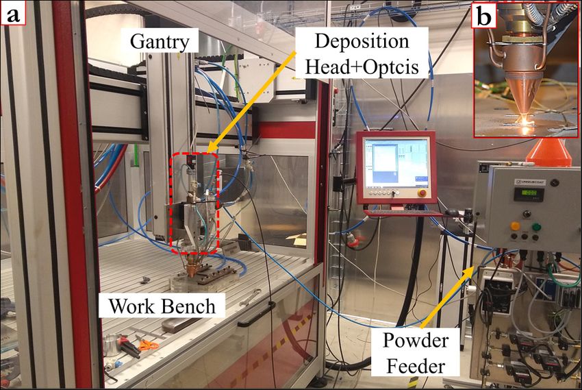
Journal of                                                                                                            ARTICLE                scitation.org/journal/jla
 Laser Applications

      FIG. 4. Plot of (a) height vs Lm; (b) width vs (HI * Lm)−0.5; (c) depth vs (HI * Lm)−0.5. The numbers by the data points indicate the corresponding trial runs (see Table II).
      (d) The effect plots indicating the significance of factors: power, speed, and feed rate (varied between low to high levels) on responses (the green bars indicate the influ-
      ence of factors on responses and the error bars conform to 95% CI).

    experiment as H* is proportional to P/V0.5. Power attenuation is low                        grain size of 40 μm as shown in Fig. 5(c) (2%–3% of the total area
    due to the low feed rates (4–10 g/min) considered in the above-                             of the deposit).
    mentioned research, which render feed rates ineffective toward width                              The top region of the deposits has distinct GBs inhabited by
    and depth. In this work, feed rates are considerably higher compared                        Nb-rich phases and eutectic phases (typically involving γ/NbC and
    to the aforementioned research and thereby assert minor influences                          γ/Laves eutectics), as shown in Figs. 5(a) and 5(d). The spectrum
    on laser-material interactions.                                                             25 shown in Fig. 5(d) indicates to the eutectic region, which has
                                                                                                higher amounts of Nb and C and moderate amounts of Fe
                                                                                                (Table III) compared to the matrix indicated by spectrum 24, sug-
    B. As-built deposits                                                                        gesting possible coexistence of NbCs and Laves phases in the eutec-
         On analysis of the AB deposit, differences in microstructural                          tics. They also display higher Nb content compared to Nb-rich
    characteristic are observed in different areas of the bead as indi-                         phases present in the GBs depicted by spectrum 26, indicating the
    cated in Fig. 3. Each single-track deposit built as per the present                         composition of a terminal solidification product.26 The middle
    experimental trial is divided into three regions: (i) top region                            region has a dendritic microstructure [Fig. 5(b)] and shows a rela-
    having equiaxed grains with an average grain size of 20 μm                                  tively lower amount of segregation with smaller particles compared
    depicted by the micrograph in Fig. 5(a) (varies between 6% and                              to the top region. The primary dendrite arm spacing (PDAS) mea-
    10% of total area of the deposit), (ii) middle region having colum-                         sured in the middle region varies between 4.5 and 7.5 μm. The
    nar dendritic microstructure with average grain size of 80 μm as                            bottom region is typified by a cellular structure [Fig. 5(c)] that
    shown in Fig. 5(b) (about 87% of the deposit), and (iii) bottom                             forms during the very early stages of solidification and epitaxial
    region consisting of cellular and columnar grains with an average                           growth, which transforms into more stable columnar dendrites and

J. Laser Appl. 33, 022024 (2021); doi: 10.2351/7.0000259                                                                                                                     33, 022024-5
© Author(s) 2021
Journal of                                                                                               ARTICLE            scitation.org/journal/jla
 Laser Applications

                                                                                                                           FIG. 5. SEM images indicating differ-
                                                                                                                           ent microstructures of sample condition
                                                                                                                           4 in AB condition within the (a) top
                                                                                                                           region, (b) middle region, and (c)
                                                                                                                           bottom region (Fig. 3 depicts the dis-
                                                                                                                           tinction between top, middlem and
                                                                                                                           bottom regions of a single-track
                                                                                                                           deposit). (d) EDS point analysis at
                                                                                                                           locations of AB sample indicated by
                                                                                                                           spectrum 24, 25, and 26 depicting
                                                                                                                           matrix, eutectic, and GB Nb-rich
                                                                                                                           phases, respectively.

    has the least amount of Nb-rich precipitates. The PDAS measures                     substructure noticed in the AB condition [Figs. 5(b) and 5(c)] van-
    for bottom region varies between 2.5 and 4 μm, indicating higher                    ishes upon ST, indicating relatively better homogeneity within the
    cooling rates compared to the middle and top regions.                               matrix. In the bottom region [Fig. 6(c)], irrespective of the process
                                                                                        parameter condition, the acicular δ phase precipitates at the GB
                                                                                        and interdendritic region.
    C. Heat treatment
    1. Solution treatment                                                               2. Solution treatment and aging
         Figures 6(a)–6(c) show micrographs depicting the top, middle,                       Following STA, microstructural morphologies of the Nb-rich
    and bottom regions of single-track deposits subjected to ST. Some                   phase and δ precipitates are as shown in Figs. 7(a)–7(c). All the
    eutectic structures present in AB deposits [Fig. 5(a)] transforms                   three micrographs indicate higher amount of δ precipitates com-
    into acicular δ + Laves phase, identified based on the appearance of                pared to the ST condition (Fig. 6). The δ phase precipitates pre-
    precipitate that has a needlelike structure27,28 as shown in Fig. 6(a),             dominantly at the GBs in the top region [Fig. 6(a)], interdendritic
    indicating the top region of the deposit. The Laves phase from the                  structures in the bottom region [Fig. 7(c)], and both at GBs and
    AB conditions is noticed predominantly at the GBs with few intra-                   interdendritic structures in the middle region [Fig. 7(b)] of the
    granular precipitates observed in the top region. In the middle                     deposit, identical in morphology and location compared to the ST
    region, δ phases precipitate at GBs and interdendritic regions. In                  conditions.
    some instances, the needlelike δ phase appears to grow from Laves
    precipitates, which is marked as δ + Laves in Fig. 6(b), as reported                3. Direct aging
    by Sivaprasad and Raman.6 The clear distinction of the                                   On DA of AB specimens, Nb-rich precipitate decreases com-
                                                                                        pared to AB and STA specimens, indicating dissolution of secon-
                                                                                        dary phases formed during the deposition process as shown in
    TABLE III. Results of EDS point analysis performed at point locations depicted in
    Fig. 5(d).                                                                          Fig. 8. δ-phase precipitates are not visible in the micrographs per-
                                                                                        taining to DA specimens, which are seen in samples subjected to
    Elements (wt. %)        Nia     Cra     Fea     C      Moa    Nba       Ti    Al    ST and STA conditions.

    Spectrum 24            50.3    20.9    19.3    2.7     2.4     2.2      0.8   0.5   4. Volume fraction analysis of Nb-rich phases on heat
    Spectrum 25            40.6    14.8    12.2    4.3     4      20        2.2   0.5   treatment
    Spectrum 26            52.6    17.3    14.7    1.2     2.7     8.3      1.9   0.1
                                                                                            The comparison of results from phase fraction analysis of
    a
     indicates a statistical error of ±0.1 wt. % on the tabulated values.               Nb-rich phases of specimens in AB, ST, STA, and DA conditions is

J. Laser Appl. 33, 022024 (2021); doi: 10.2351/7.0000259                                                                                                   33, 022024-6
© Author(s) 2021
Journal of                                                                                ARTICLE           scitation.org/journal/jla
 Laser Applications

                                                                                                           FIG. 6. Micrographs of specimen 4
                                                                                                           upon ST at (a) top region, depicting
                                                                                                           eutectic and Laves phases; (b) middle
                                                                                                           region, depicting Laves and δ phases;
                                                                                                           and (c) bottom region, depicting Laves
                                                                                                           and δ phases.

    suggestive of the dissolution of Nb-rich phases as shown in          fraction estimations. Some common aspects can be noticed based on
    Figs. 9(a)–9(c). The Vf of Nb-rich phases in the AB condition con-   evaluation of %Vf of Nb-rich phases, which are (i) in cases having
    siders amount of Laves and NbCs, whereas on heat treatment, the δ    high %Vf of Nb-rich phases (Vf > 4%) in the AB condition, the segre-
    phase is also considered in addition to Laves and NbCs in phase      gation decreases upon ST in the top and middle regions; (ii) in the

                                                                                                           FIG. 7. Micrographs of specimen 4
                                                                                                           upon STA at (a) top region, depicting
                                                                                                           eutectic and Laves phases; (b) middle
                                                                                                           region, depicting Laves and δ phases;
                                                                                                           and (c) bottom region, depicting Laves
                                                                                                           and δ phases.

J. Laser Appl. 33, 022024 (2021); doi: 10.2351/7.0000259                                                                                  33, 022024-7
© Author(s) 2021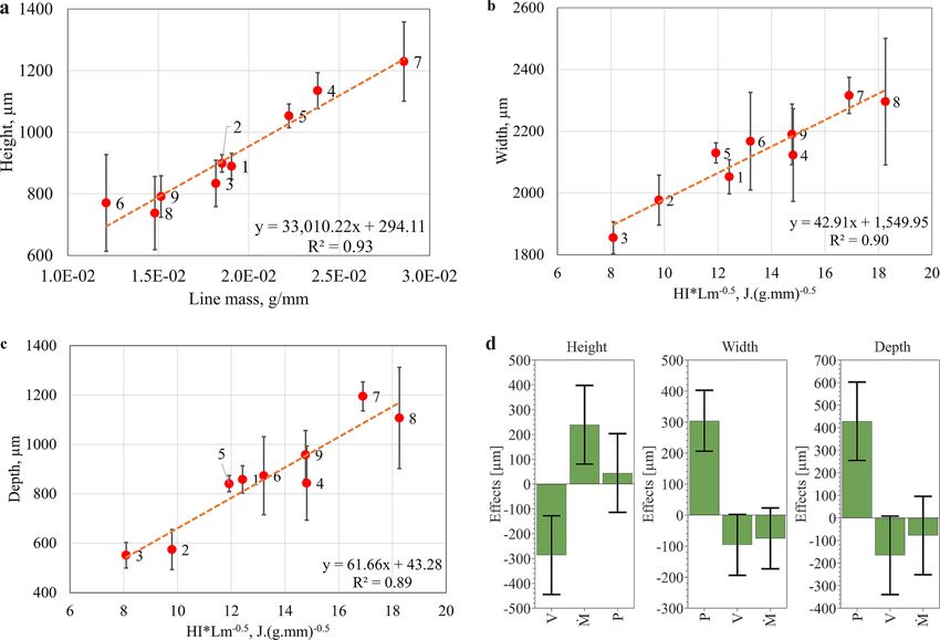
Journal of                                                                                   ARTICLE            scitation.org/journal/jla
 Laser Applications

                                                                                                               FIG. 8. Micrographs of specimen 4
                                                                                                               upon DA at (a) top region, depicting
                                                                                                               eutectic and Laves phases; (b) middle
                                                                                                               region, depicting Laves and NbC
                                                                                                               phases; and (c) bottom region, depict-
                                                                                                               ing Laves and NbC phases.

    middle and bottom regions, upon STA, the %Vf of Nb-rich phases          testing is performed in the top, middle, and bottom regions of AB,
    increases compared to ST specimens, possibly due to the growth of       ST, STA, and DA conditions. The variation in hardness values
    delta phase on aging; (iii) upon DA in most cases, a reduced %Vf of     measured in any region of deposit (top, middle, or bottom region)
    Nb-rich phases are recorded compared to AB and STA conditions.          varies about ±15 HV around the average value for all deposits.
         The specimen conditions 1 and 2 show higher amount of              Therefore, the average value of hardness for each experimental trial
    Nb-rich phases in the AB condition compared to 3–9, which are           is shown in Fig. 10. The hardness of AB samples varies between
    processed with a power of 1200 W. A low power condition coupled         280 HV and 320 HV, similar to the hardness values reported by
    with a high feed rate and a small spot diameter is ideal for the for-   Kistler et al.25 for low-rate deposition specimens, which reduces to
    mation of higher amount of precipitates in the top region of the        about 250 HV on ST. The STA and DA specimens show relatively
    deposit as per the research of Sreekanth et al.11 Further elaboration   higher hardness (>400 HV apart from sample condition 2) com-
    regarding the solidification and influence of power on Nb-rich          pared to unaged specimens, possibly due to the precipitation of γ0
    phases are provided in Sec. IV B.                                       and γ00 phases. Devaux et al.29 carried out heat treatments to deter-
         Although the Vf analysis provides evidence of dissolution of       mine the kinetics of γ00 precipitates, which showed the existence of
    Nb-rich phases, for confirmation, EDS point analysis is carried out     strengthening phases in solutionizing and aging conditions consid-
    in AB and heat-treated conditions for the specimen from trial run       ered in this work. Sample condition 2 shows a hardness value of
    2 as shown in Fig. 9(d). It shows increasing amounts of Nb content      325 HV on the DA condition, which is anomalous compared to
    in the matrix in ST and STA conditions, plausibly due to the disso-     other DA processed specimens. Since DA specimens are directly
    lution of Nb-rich phases as shown in Fig. 9(d). Also, an increasing     processed from the AB condition and sample 2 in the AB condition
    trend in Nb concentration is seen from top to bottom of a single-       shows a high amount of Nb-rich precipitate [Figs. 9(a)–9(c)], lower
    track deposit for a given process condition, indicating better homo-    precipitation of γ0 and γ00 phases occur in this condition reducing
    geneity at the bottom of the bead. Distribution coefficient, defined    the mean hardness in the top, middle, and bottom regions.
    as the ratio of wt. %. Nb in the dendrite cores to wt. %. Nb in the
    powder (4.9 wt. %) is calculated from the results of EDS analysis,
    which can be found on top of each bar in Fig. 9(d). In case of the      IV. DISCUSSION
    top region, the central part of the grain as indicated by spectrum      A. Deposit geometry
    24 in Fig. 5(d) is considered a core for EDS analysis.
                                                                                  The geometry of single-track deposits is important as the
                                                                            resulting bead dimensions are responsible for defining the features
    D. Hardness testing                                                     of a 3D build, such as the size and surface roughness. The metallur-
         In order to study the influence of processing parameters and       gical bonding and remelting of layers also depend on the size and
    heat treatments on single-track deposits, micro-Vickers hardness        shape of discrete tracks as stated by Beaman et al.,30 and high

J. Laser Appl. 33, 022024 (2021); doi: 10.2351/7.0000259                                                                                      33, 022024-8
© Author(s) 2021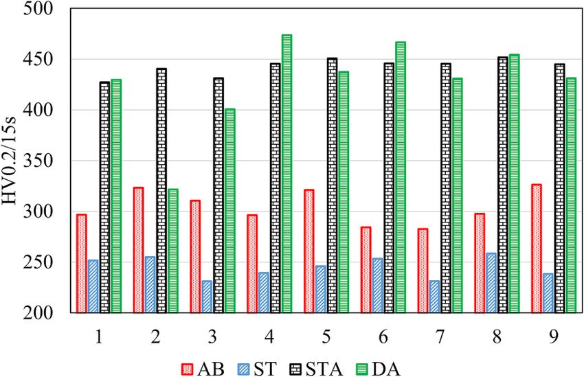
Journal of                                                                                                          ARTICLE                scitation.org/journal/jla
 Laser Applications

      FIG. 9. Plot showing %Vf Nb-rich phases in (a) top region, (b) middle region, and (c) bottom region after heat treatment (Sec. II E). (d) EDS quantification results showing
      wt. %. Nb in the dendrite cores for different specimen conditions (the numbers on top of each bar represents distribution coefficient).

                                                                                               deposition rate results in higher volume of material deposition,
                                                                                               which implies higher productivity. As seen in Sec. III A, the height
                                                                                               of the tracks depends on Ṁ /V and is insensitive to variations in
                                                                                               power. Increase in the feed rate under constant speed introduces
                                                                                               more material per unit time into the melt pool and, consequently,
                                                                                               increases the height of the bead (provided sufficient power).
                                                                                               Conversely, increase in speed reduces the amount of material fed
                                                                                               into the melt pool and correspondingly decreases height. Increase in
                                                                                               laser power increases the energy density, but spot diameter effectively
                                                                                               remains unaltered. The energy-material interaction volume shows
                                                                                               minimal changes with increase in power, and thereby the effect of
                                                                                               power conditions can be neglected in determining height of the
                                                                                               deposits. Similar conclusions are put forth by Segerstark et al.16 and
                                                                                               de Oliveira et al.24 on evaluation of L-DED single-track deposits. If
                                                                                               the power conditions are insufficient to melt the feed rate of the
      FIG. 10. Vickers microindentation hardness (HV0.2) measurements of speci-
                                                                                               material considered, variation in power affects height as shown by El
      mens in AB, ST, STA, and DA conditions.
                                                                                               Cheikh et al.31 where track height is a function of P * Ṁ 3/V4.

J. Laser Appl. 33, 022024 (2021); doi: 10.2351/7.0000259                                                                                                                   33, 022024-9
© Author(s) 2021
Journal of ARTICLE scitation.org/journal/jla
Laser Applications
Width is primarily influenced by laser spot diameter and morphology of Nb-rich precipitates from continuous bands in AB
powder focus diameter, which are kept constant in the present set condition to discrete globular or irregular shaped precipitates upon
of experiments.11 If speed is constant, then increase in power and heat treatment is observed. The dissolution of Laves phase is
feed rate increases the width as per the study by Zhang et al.32 due recorded by Sivaprasad et al.39 when performing ST on electron
to the material availability and high flowability of melt under beam welded Alloy 718 specimens at 980 °C/ 0.5 h, where upon
excess power condition. With increase in speed, both line mass and claims are made regarding Laves phase as an ideal nucleation site
heat input decrease as per Eqs. (1) and (2). If the energy is higher for δ precipitates. The dissolution of Nb-rich phases in the present
than that needed for melting the powder, then the remainder of the work is recorded for ST performed at 954 °C/1 h, indicating no
energy is utilized in melting the substrate, effecting an increase in major change in diffusion of Nb between the two ST temperature
depth.33 Hence, the combined effect of power, speed, and feed rate ranges. Also, the increase in time from 0.5 to 1 h promotes more
becomes important in influencing the width and depth measures. diffusion of Nb. δ phase precipitating from Nb-rich phases in the
The research by de Oliveira et al.24 shows that width and depth can middle region and eutectics in the top region of ST and STA condi-
be expressed as a function of P/V0.5 and the research by Kistler tions (see Figs. 6 and 7) is identical to the predictions made by
et al.25 correlates width to a process factor P/(Ds × V)0.5. The exclu- Kumara et al.40 on phase field modeling of L-DED Alloy 718.
sion of feed rate in the expression is due to the minimal interaction Furthermore, the model predicts 3.5%Vf Nb-rich phases in regions
between laser-beam and powder particles, which is contradictory to having PDAS of 7.1 μm, which corresponds to the middle region of
the current research and considers low heat input for high feed-rate the deposits (PDAS: 5–7.5 μm) in the present work, wherein the Vf
deposition. Nb-rich phases vary between 3% and 4% in most cases as shown in
Fig. 9(b).
B. As-built condition The rate of nucleation and growth of δ-phase precipitate is
high in specimens subjected to ST conditions (954 °C/1 h), which is
The solidification in L-DED Alloy 718 starts by epitaxial
supported by the study by Wei et al.41 The study claims that, under
growth of grains (no undercooling) from the substrate as the
various thermomechanical conditions, the temperature range
energy needed for both homogeneous and heterogeneous nucle-
between 900 and 950 °C facilitates δ precipitation preferentially in
ation is higher.34 Initially small protrusions are developed in the
GBs above which (950–1000 °C) dislocations are more preferable
melt, which grow into cellular and dendritic microstructures.35 The
for precipitation. Dislocations sites are favorable for precipitation of
dendritic core thus formed consists of elements such as Ni and Fe,
the δ phase due to the high interfacial energy promoting nucleation
whereas the refractory elements like Nb partition into liquid melt.36
as purported by Sundararaman et al.42 As it can be seen in Figs. 6
As a result of compositional gradient of Nb in the dendritic core
and 7, GBs and interdendritic regions are preferable sites for δ pre-
and the interdendritic regions, high amount of Nb-rich phases are
cipitation in this work implying the precipitation preference of δ
formed in the interdendritic regions and GBs of the deposit as seen
phase at both GB and dislocation.
in Figs. 5(a)–5(c), which concur with the observation made by
Higher δ-phase density is noticed in the top and bottom
Cieslak et al.37 High cooling rates limit lateral diffusion of Nb due
regions of the deposits, which have the highest and lowest %Vf of
to many protrusions growing simultaneously and low temperature
Nb-rich phases, respectively. The dissolution of Nb-rich eutectics
gradient that exists laterally, creating near isothermal conditions
in the top region and higher distribution coefficient indicating
that hinder diffusion (and heat flux) resulting in smaller grains at
better Nb homogeneity of bottom region [Fig. 9(d)] in ST and STA
the bottom region of the deposits compared to the middle regions.
conditions presumably provide the Nb for δ precipitation.
A high thermal gradient (G) at the bottom region of deposits
Moreover, the average grain sizes in the top, middle, and bottom
(G > 0) promotes a columnar dendritic structure.34 A monotonic
regions are 22, 80, and 45 μm, respectively, as estimated by the line
decrease in G along the height of the melt pool (G < 0) results in
intercept method. Upon dissolution under ST conditions, the sub-
columnar-equiaxed transition (CET), paving the way for equiaxed
structure boundaries are obliterated as shown in Figs. 6(a)–6(c),
grains as purported by Kurz et al.38 This CET phenomenon is the
and the diffusion length increases. Hence, fewer δ precipitates are
principle reason for the formation of equiaxed grains in the top
formed in the middle region due to longer diffusion lengths given
region of deposits. When the energy density is very high (high
the bigger grain sizes.
power), the G > 0 condition prevails until the end of solidification,
On DA, dissolution of the Nb-rich phase is confirmed by
resulting in a complete columnar dendritic structure with a few
reduction of %Vf Nb-rich precipitates between DA and AB speci-
equiaxed grains in the top region of the deposit. Hence, in the case
mens, as shown by the plot in Fig. 9. The size, morphology, stoichi-
of high-power conditions (specimen 4–9), low amounts of Nb-rich
ometry, and location play an important role in the dissolution of
phases are noticed in the top region. At low power conditions, CET
the Laves phase as reported by Ram et al.20 Coarser precipitates
forms in the early stages of solidification paving way for heteroge-
with higher Nb concentrations (wt. %) require longer dissolution
neous nucleation of grains and increase in segregation of Nb-rich
time compared to fine Nb-rich precipitates processed under iso-
phases compared to high-power condition, which is observed in
thermal temperatures. Ram et al.43 also reports that the Nb-rich
the top regions of specimen conditions 1 and 2.
precipitate size of laser processed Alloy 718 is finer and undergoes
faster dissolution compared to the precipitates formed in arc-
C. Heat treatments welding of Alloy 718 under ST conditions. A relatively smaller
On subjecting AB specimens to ST, STA, and DA treatments, Nb-rich precipitate size formed in the present work, similar to the
partial dissolution of Nb-rich phases is noticed. A change in laser welded specimens mentioned above, could aid in dissolution
J. Laser Appl. 33, 022024 (2021); doi: 10.2351/7.0000259 33, 022024-10
© Author(s) 2021Journal of ARTICLE scitation.org/journal/jla
Laser Applications
of such precipitates. Eutectic structures [spectrum 25, Fig. 5(d)] (1) The analysis of geometrical characteristics of a single-track
having Nb concentrations up to 20 wt. % (Table III) require higher deposit shows that the height of the deposit is primarily a func-
amounts of diffusion of Nb for dissolution compared to GB tion of feed rate and deposition speed. It increases with
Nb-rich precipitates [spectrum 26, Fig. 5(d)], which contain increase in feed rates and decrease in scanning speeds and
9 wt. % Nb. Figure 8(a) depicts the dissolution of GB Nb-rich remains unaffected by variation in laser power. The width and
phases on DA, whereas the eutectic phases remain intact showing depth of deposits are primarily a function of laser power and
the influence of Nb concentration on dissolution reaction. The minimally influenced by speed and feed rate, which varies in
eutectics in ST and STA solutionize to pave the way for δ precipita- correlation to the factor P/(V × Ṁ )0.5.
tion due to the higher processing temperature compared to the (2) The microstructure of an L-DED deposit shows three distinc-
eutectics in DA condition. tive regions divided based on the difference in microstructural
No δ precipitate is discernible in micrographs [Figs. 8(a)–8(c)] features. The bottom-most region immediately adjacent to the
as the aging temperatures considered in this study do not facilitate substrate shows cellular and columnar dendritic microstructure
the formation of the δ phase. The research by Azadian et al.27 and the top-most part of the deposit consists of equiaxed
showed no precipitation of the δ phase for specimens subjected to grains formed due to CET. The middle region displays colum-
isothermal treatment of Alloy 718 below 800 °C. It is reported in nar dendritic microstructures with well-developed secondary
the same study that the temperature range of 700–900 °C is insuffi- dendrites having larger grain size and substructural scales com-
cient for nucleation and extensive growth of the δ phase. Also, the pared to the bottom region.
results of isothermal heat treatment at 718 °C for 10 000 h showed (3) On solution treatment, δ-phase precipitation occurs predomi-
no precipitation as per the research of Brooks and Bridges,44 which nantly in the top and bottom regions of the deposit due to rel-
suggests the insufficiency of aging temperature considered in this atively smaller diffusion distances of Nb owing to the grain
work for δ precipitation. sizes (20 and 45 μm, respectively), as opposed to the middle
region that has fairly lower amounts of δ precipitation. The δ
precipitation occurs preferentially at grain boundaries and
D. Hardness testing interdendritic regions. The subsequent aging treatment of
solution-treated specimen results in higher density δ precipi-
The hardness values in Alloy 718 can be influenced by metal-
tates. No δ precipitation is identified in the direct aged condi-
lurgical factors such as alloy chemistry, precipitation morphology,
tion, which indicates that no nucleation of δ phase occurs at
precipitation density, grain size, and material stress state.23 The top,
temperatures ranging between 621 and 718 °C. Eutectic struc-
middle, and bottom regions with varying amounts of Nb-rich
tures having high Nb concentration are solutionized on sub-
phase (Fig. 9) shows minimal variation in hardness response and
jecting AB specimens to ST and STA conditions, but remain
no grain growth is noticed on subjecting specimens to heat treat-
intact upon DA treatment.
ment. The γ0 phase has fast precipitation kinetics,45 which could be
(4) The phase fraction analysis indicate dissolution of Nb-rich
the primary reason for higher hardness response, with minimal
phases on subjecting AB deposits to ST, STA, and DA condi-
contributions from residual stresses and Nb-rich phases. The varia-
tions, which is further confirmed by elemental analysis (EDS
tion in hardness values of STA specimens showed less deviation
point analysis).
compared to DA specimens. STA specimens showed better homo-
geneity in Nb concentration [Fig. 9(d)] that results in more
uniform precipitation of strengthening precipitates compared to
DA samples and thereby shows minimal variations. ACKNOWLEDGMENTS
The authors would like to acknowledge GKN Aerospace for
continual support toward the research. The help from Arun
V. CONCLUSIONS Ramanathan Balachandramurthi in performing EDS analysis is
The present work investigates the influence of variation of gratefully acknowledged.
processing parameters such as laser power, deposition speed, and
feed rates processed at a unique window accommodating high dep-
osition rate, and subsequent heat treatments on deposit properties REFERENCES
1
such as geometry of bead, Nb-rich phase content, and hardness. In W. Gao, Y. Zhang, D. Ramanujan, K. Ramani, Y. Chen, C. B. Williams,
general, the study establishes that the formation of the Nb-rich C. C. L. Wang, Y. C. Shin, S. Zhang, and P. D. Zavattieri, “The status, challenges,
phase in L-DED is sensitive to process parameters and heat treat- and future of additive manufacturing in engineering,” Comput. Aided Des. 69,
ments, which aids as an effective way for choosing parameters for 65–89 (2015).
2
3D deposition. The process parameter-geometry relationships are R. E. Schafrik, D. D. Ward, and J. R. Groh, Superalloys 718, 625, 706 and
Various Derivatives (The Minerals, Metals and Materials Society, Warrendale,
similar to those obtained in low deposition rate studies for a
PA, 2001).
Co-based alloy system and hence show stability and reproducibility 3
J. F. Barker, E. W. Ross, and J. F. Radavich, “Long time stability of Inconel 718,”
of DED experiments. Few generalizations can be drawn for micro- JOM 22, 31–41 (2015).
structural results as they depend on the temperature and stress state 4
J. Andersson, G. P. Sjöberg, L. Viskari, and M. C. Chaturvedi, “Effect of solu-
of materials, and each case needs to be discretely considered and tion heat treatments on superalloys Part 1—Alloy 718,” Mater. Sci. Technol. 28,
evaluated. 609–619 (2013).
J. Laser Appl. 33, 022024 (2021); doi: 10.2351/7.0000259 33, 022024-11
© Author(s) 2021Journal of ARTICLE scitation.org/journal/jla
Laser Applications
5
S. Antonov, W. Chen, S. Lu, D. Isheim, D. N. Seidman, Q. Feng, E. Sun, and Inconel®718: Microstructure, fusion zone morphology, and hardness,” J. Laser
S. Tin, “The effect of phosphorus on the formation of grain boundary laves Appl. 29, 022005 (2017).
phase in high-refractory content Ni-based superalloys,” Scr. Mater. 161, 44–48 26
J. N. DuPont, J. C. Lippold, and S. D. Kiser, Welding Metallurgy and
(2019). Weldability of Nickel-Base Alloys (John Wiley & Sons, Hoboken, NJ, 2009).
6
K. Sivaprasad and S. G. S. Raman, “Influence of weld cooling rate on micro- 27
S. Azadian, L. Y. Wei, and R. Warren, “Delta phase precipitation in Inconel
structure and mechanical properties of alloy 718 weldments,” Metall. Mater. 718,” Mater. Charact. 53, 7–16 (2004).
Trans. A 39, 2115–2127 (2008). 28
M. Anderson, A. L. Thielin, F. Bridier, P. Bocher, and J. Savoie, “δ phase pre-
7
J. J. Schirra, R. H. Caless, and R. W. Hatala, Superalloys 718, 625 and Various cipitation in Inconel 718 and associated mechanical properties,” Mater. Sci. Eng.
Derivatives (The Minerals, Metals and Materials Society, Pittsburgh, PA, 1991). A 679, 48–55 (2017).
8
Y. Chen, K. Zhang, J. Huang, S. R. E. Hosseini, and Z. Li, “Characterization of 29
A. Devaux, L. Nazé, R. Molins, A. Pineau, A. Organista, J. Y. Guédou,
heat affected zone liquation cracking in laser additive manufacturing of Inconel J. F. Uginet, and P. Héritier, “Gamma double prime precipitation kinetic in alloy
718,” Mater. Des. 90, 586–594 (2016). 718,” Mater. Sci. Eng. A 486, 117–122 (2008).
9 30
J. F. Radavich, Superalloys 718 Metallurgy and Applications (The Minerals, J. Beaman, C. Atwood, T. Bergman, D. Bourell, S. Hollister, and D. Rosen,
Metals and Materials Society, Pittsburgh, PA, 1989). Additive/Subtractive Manufacturing Research and Development in Europe (World
10
A. J. Pinkerton, “Advances in the modeling of laser direct metal deposition,” Technology Evaluation Center Inc., Baltimore, MD, 2004).
J. Laser Appl. 27, S15001 (2015). 31
H. El Cheikh, B. Courant, S. Branchu, J.-Y. Hascoët, and R. Guillén, “Analysis
11
S. Sreekanth, E. Ghassemali, K. Hurtig, S. Joshi, and J. Andersson, “Effect of and prediction of single laser tracks geometrical characteristics in coaxial laser
direct energy deposition process parameters on single-track deposits of alloy cladding process,” Opt. Lasers Eng. 50, 413–422 (2012).
718,” Metals 10, 96 (2020). 32
K. Zhang, W. Liu, and X. Shang, “Research on the processing experiments of
12
L. Costa and R. Vilar, “Laser powder deposition,” Rapid Prototyping J. 15, laser metal deposition shaping,” Opt. Laser Technol. 39, 549–557 (2007).
33
264–279 (2009). R. M. Mahamood, Laser Metal Deposition Process of Metals, Alloys, and
13
C. Zhong, T. Biermann, A. Gasser, and R. Poprawe, “Experimental study of Composite Materials (Springer International Publishing AG, Cham, 2018).
34
effects of main process parameters on porosity, track geometry, deposition rate, J. N. DuPont, in Welding Fundamentals and Processes, edited by S. T. Lienert,
and powder efficiency for high deposition rate laser metal deposition,” J. Laser S. Babu, and V. Acoff (ASM International, Novelty, OH, 2011), pp. 96–114.
Appl. 27, 042003 (2015). 35
D. A. Porter, K. E. Easterling, and K. E. Easterling, Phase Transformations in
14
S. Sui, C. Zhong, J. Chen, A. Gasser, W. Huang, and J. H. Schleifenbaum, Metals and Alloys (Revised Reprint), 3rd ed. (CRC Press, Boca Raton, FL, 2009).
“Influence of solution heat treatment on microstructure and tensile properties of 36
S. G. K. Manikandan, D. Sivakumar, K. Prasad Rao, and M. Kamaraj, “Laves
Inconel 718 formed by high-deposition-rate laser metal deposition,” J. Alloys phase in alloy 718 fusion zone—Microscopic and calorimetric studies,” Mater.
Compd. 740, 389–399 (2018). Charact. 100, 192–206 (2015).
15
A. Dass and A. Moridi, “State of the art in directed energy deposition: From 37
M. J. Cieslak, G. A. Knorovsky, T. J. Headley, and J. A. D. Romig, Superalloys
additive manufacturing to materials design,” Coatings 9, 418 (2019). 718 Metallurgy and Applications (The Minerals, Metals and Materials Society,
16
A. Segerstark, J. Andersson, and L.-E. Svensson, “Investigation of laser metal Pittsburgh, PA, 1989).
deposited alloy 718 onto an EN 1.4401 stainless steel substrate,” Opt. Laser 38
W. Kurz, C. Bezençon, and M. Gäumann, “Columnar to equiaxed transition
Technol. 97, 144–153 (2017). in solidification processing,” Sci. Technol. Adv. Mater. 2, 185–191 (2001).
17
Y. S. Song, M. R. Lee, and J. T. Kim, Superalloys 718, 625, 706 and Various 39
K. Sivaprasad, S. G. S. Raman, and A. S. Rao, “A novel method of estimating
Derivatives (The Minerals, Metals and Materials Society, Pittsburgh, PA, 2005). the Laves phase in electron beam welded alloy 718,” Pract. Metallogr. 45,
18
J. P. Stroup and R. A. Heacox, “Effect of grain size variations on the long-time 271–282 (2008).
stability of alloy 718,” JOM 21, 46–54 (1969). 40
C. Kumara, A. Segerstark, F. Hanning, N. Dixit, S. Joshi, J. Moverare, and
19
W. Mankins and S. Lampman, in Heat Treating of Nonferrous Alloys, edited P. Nylén, “Microstructure modelling of laser metal powder directed energy depo-
by G. E. Totten (ASM International, Novelty, OH, 2016), Vol. 4E, pp. 426–458. sition of alloy 718,” Addit. Manuf. 25, 357–364 (2019).
20
G. D. J. Ram, A. V. Reddy, K. P. Rao, and G. M. Reddy, “Control of laves 41
X. P. Wei, W. J. Zheng, Z. G. Song, T. Lei, Q. L. Yong, and Q. C. Xie,
phase in Inconel 718 GTA welds with current pulsing,” Sci. Technol. Weld. “Strain-induced precipitation behavior of δ phase in Inconel 718 alloy,” J. Iron
Joining 9, 390–398 (2013). Steel Res. Int. 21, 375–381 (2014).
21
SAE-AMS 5663N: Aerospace Material Specification (SAE International, 42
M. Sundararaman, P. Mukhopadhyay, and S. Banerjee, “Precipitation of the
Warrendale, PA, 2016). δ-Ni3Nb phase in two nickel base superalloys,” Metall. Trans. A 19, 453–465 (1988).
22
M. B. Henderson, D. Arrell, R. Larsson, M. Heobel, and G. Marchant, “Nickel 43
G. D. J. Ram, A. V. Reddy, K. P. Rao, G. M. Reddy, and J. K. S. Sundar,
based superalloy welding practices for industrial gas turbine applications,” Sci. “Microstructure and tensile properties of Inconel 718 pulsed Nd-YAG laser
Technol. Weld. Joining 9, 13–21 (2013). welds,” J. Mater. Process. Technol. 167, 73–82 (2005).
23
E. Broitman, “Indentation hardness measurements at macro-, micro-, and 44
J. W. Brooks and P. J. Bridges, “Metallurgical stability of Inconel alloy 718,” in
nanoscale: A critical overview,” Tribol. Lett. 65, 23 (2016). Superalloys 1988: Proceedings of the Sixth International Symposium, Champion,
24
U. de Oliveira, V. Ocelík, and J. T. M. De Hosson, “Analysis of coaxial laser PA, Sept. 18–22, 1988 (The Minerals, Metals and Materials Society, Pittsburgh,
cladding processing conditions,” Surf. Coat. Technol. 197, 127–136 (2005). PA, 1988).
25 45
N. A. Kistler, A. R. Nassar, E. W. Reutzel, D. J. Corbin, and A. M. Beese, J. F. Radavich, Superalloys 718, 625, 706 and Various Derivatives (The
“Effect of directed energy deposition processing parameters on laser deposited Minerals, Metals and Materials Society, Pittsburgh, PA, 1997).
J. Laser Appl. 33, 022024 (2021); doi: 10.2351/7.0000259 33, 022024-12
© Author(s) 2021You can also read