Numerical Analysis of Filament Wound Cylindrical Composite Pressure Vessels Accounting for Variable Dome Contour - MDPI
←
→
Page content transcription
If your browser does not render page correctly, please read the page content below
Article
Numerical Analysis of Filament Wound Cylindrical Composite
Pressure Vessels Accounting for Variable Dome Contour
Kumar C. Jois * , Marcus Welsh                    , Thomas Gries and Johannes Sackmann

                                           Institut für Textiltechnik Aachen (ITA), RWTH Aachen University, 52074 Aachen, Germany;
                                           marcus.welsh@rwth-aachen.de (M.W.); Thomas.Gries@ita.rwth-aachen.de (T.G.);
                                           Johannes.Sackmann@ita.rwth-aachen.de (J.S.)
                                           * Correspondence: kumar.jois@rwth-aachen.de

                                           Abstract: In this work, the stress distribution along cylindrical composite pressure vessels with
                                           different dome geometries is investigated. The dome contours are generated through an integral
                                           method based on shell stresses. Here, the influence of each dome contour on the stress distribution
                                           at the interface of the dome-cylinder is evaluated. At first, the integral formulation for dome curve
                                           generation is presented and solved for the different dome contours. An analytical approach for
                                           the calculation of the secondary stresses in a cylindrical pressure vessel is introduced. For the
                                           analysis, three different cases were investigated: (i) a polymer liner; (ii) a single layer of carbon-epoxy
                                           composite wrapped on a polymer liner; and (iii) multilayer carbon-epoxy pressure vessel. Accounting
                                           for nonlinear geometry is seen to have an effect on the stress distribution on the pressure vessel, also
                                           on the isotropic liner. Significant secondary stresses were observed at the dome-cylinder interface
                                           and they reach a maximum at a specific distance from the interface. A discussion on the trend in
                                           these stresses is presented. The numerical results are compared with the experimental results of the
                                           multilayer pressure vessel. It is observed that the secondary stresses present in the vicinity of the
                                 dome-cylinder interface has a significant effect on the failure mechanism, especially for thick walled

                                           cylindrical composite pressure vessel. It is critical that these secondary stresses are directly accounted
Citation: Jois, K.C.; Welsh, M.;           for in the initial design phase.
Gries, T.; Sackmann, J. Numerical
Analysis of Filament Wound                 Keywords: composite pressure vessel; CPV; COPV; stress distribution; secondary stress; carbon-
Cylindrical Composite Pressure
                                           epoxy composites; cylindrical pressure vessel; failure mechanism; numerical analysis
Vessels Accounting for Variable Dome
Contour. J. Compos. Sci. 2021, 5, 56.
https://doi.org/10.3390/jcs5020056

                                           1. Introduction
Academic Editor: Frédéric Jacquemin
Received: 15 January 2021                       Pressure vessels are containers used to store fluid under pressure. They are more
Accepted: 8 February 2021                  commonly used to store gases, rather than liquids, due to the compressibility and hence
Published: 11 February 2021                the possibility to achieve high energy density [1]. In stationary applications, where weight
                                           and space are not of much concern, pressure vessels are usually manufactured using
Publisher’s Note: MDPI stays neu-          metals. However, the situation becomes rather interesting for mobile applications, like
tral with regard to jurisdictional clai-   propellant tanks for rockets or satellites, compressed natural gas and hydrogen tanks for
ms in published maps and institutio-       automotive application, etc. While the shape of the pressure vessel can vary depending
nal affiliations.                          on the application, cylindrical pressure vessels are the most common among them. In this
                                           study, cylindrical pressure vessels and some of their design aspects are addressed.
                                                There are two types of stresses, namely hoop and longitudinal stress, acting on a
Copyright: © 2021 by the authors. Li-
                                           cylinder under internal pressure. An isotropic material for manufacturing these cylinder
censee MDPI, Basel, Switzerland.
                                           leads to a redundant material usage. This has a considerable impact at higher pressure,
This article is an open access article
                                           especially for mobile applications. Composite materials, due to the possibility of obtaining
distributed under the terms and con-       highly orthotropic structures, offer an alternative to purely isotropic materials. A vessel
ditions of the Creative Commons At-        manufactured using composite materials is referred to in this article as a composite pressure
tribution (CC BY) license (https://        vessel (CPV). More specifically, CPV’s are often used when one requires high-strength, min-
creativecommons.org/licenses/by/           imal weight, or both simultaneously. This happens to be the case, for example, with solid
4.0/).                                     rocket motors, which generally have quite high internal pressure to achieve high thrust;

J. Compos. Sci. 2021, 5, 56. https://doi.org/10.3390/jcs5020056                                                  https://www.mdpi.com/journal/jcs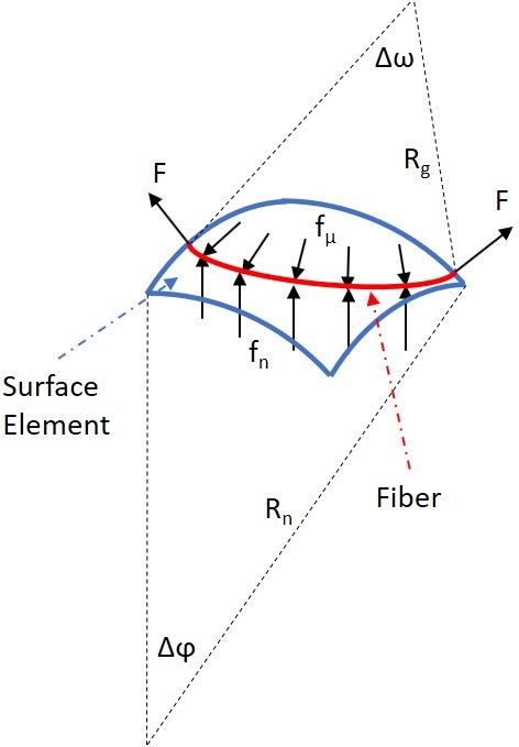
J. Compos. Sci. 2021, 5, 56                                                                                            2 of 15

                              however, they must also be light-weight in order to maximize the available payload mass
                              that can be delivered into orbit [2].
                                    CPV’s, as a technology, are quite old and were mostly used in the early days for
                              rocket motor casings and space related applications [2]. While this technology may be
                              perfected for space applications, where manufacturing speeds and costs do not play a major
                              role, automotive applications, however, have costs limits and require high manufacturing
                              speeds. Over the past decade there has been a major movement towards alternatives
                              to the conventional combustion engine due to its “enhancing” of the greenhouse effect.
                              One proposed alternative is the hydrogen fuel cell automobile, which would require a
                              hydrogen source. Due to some practical reasons, gaseous hydrogen has found its way to
                              the market for this purpose, compared to cryogenic hydrogen. Hydrogen, having a density
                              of 0.0838 kg/m3 (energy density of 10 MJ/m3 ) at 273 K and 0.1 MPa, must be stored at
                              higher pressure to achieve the required coverage distance. For automotive application,
                              the pressure is about 70 MPa, at which hydrogen has a density of 41.74 kg/m3 at 273 K
                              (energy density of 5000 MJ/m3 ) [1].
                                    There are different types of CPV based on the composite coverage. Here, a Type IV
                              pressure vessel is considered. This consists of a polymer liner and a composite overwrap,
                              manufactured by means of filament winding. Other techniques like overbraiding is also
                              known to be used for cylindrical pressure vessel [3]. The concept of the filament winding is
                              rather simple: a long, continuous fibre is wrapped around a form, referred to as a mandrel
                              or liner, until the final form and thickness is achieved. The matrix material, most commonly
                              an epoxy, can be applied in a few different ways: the fibres can be impregnated with the
                              epoxy before winding begins (Prepregs) or after winding has been completed (through
                              suitable resin infusion process), or the fibres can be impregnated with the epoxy during the
                              winding process, in which the fibres are pulled through a bath containing the epoxy [4].
                              The resins can be either thermosets (e.g., epoxy-based, vinyl ester) or thermoplastics
                              (usually in Prepreg form).
                                    Keeping lightweight and cost in mind, a minimum amount of fibre must be used.
                              In filament winding, though a continuous process, one can differentiate the composite
                              overwrap into different layers or plies. There are different plies oriented at different angles
                              (in this case, the vessel longitudinal axis is considered as 0◦ ). Due to a physical network of
                              fibres, netting theory is commonly used for a preliminary analysis [5,6]. Zhang et al. [7]
                              uses netting theory to determine the laminate layout for the cylindrical section. Classical
                              lamination theory is also among the techniques [8]. Another technique for analysis is finite
                              element tools/solvers (FE). Gray and Moser [9] discusses the effect of material and geomet-
                              ric nonlinearity on designing of CPV’s, by considering an axisymmetric model. Multhoff
                              and Krieger [10] present an effective design procedure for hydrogen storing CPV. A soft-
                              ware tool is developed for a rapid modelling and analysis of CPV. Magneville et al. [11]
                              discusses the various modelling parameters for Type IV composite pressure vessels for
                              hydrogen storage. Various FE techniques are provided for the analysis of CPV [12–14].
                                    The load sharing ability of different liner material is compared in [15], where the
                              stresses along the length of the liner is plotted. To this end, they mention about the complex
                              stress state at the dome-cylinder interface, where stress peaks are observed, irrespective
                              of the liner material. Lin et al. [16] observed higher matrix cracking at the dome-cylinder
                              interface through the SEM analysis, in comparison to the cylindrical section. This region
                              was seen to be prone to high stress concentration during the hydrostatic test. This article
                              analyses the effect of different dome geometries on the stress distribution at the dome-
                              cylinder interface.

                              2. Dome Design
                                   A cylindrical pressure vessel can be divided into three sections; a cylindrical section
                              and two domes. The valves or boss is attached to one end of the dome as shown in the
                              Figure 1 and these are usually symmetric, meaning both domes are similar, but they can
                              also vary depending on the application.
J. Compos. Sci. 2021, 5, 56 3 of 15
Dome-cylinder
interface
dome section
cylindrical section
valve / boss
Figure 1. Sections of a polymer liner/mandrel with boss connection.
In filament winding, one can differentiate between geodesic and non-geodesic paths
for the fibre. While the designing and the winding of the cylindrical section can be
done with relative ease, doing this for the dome section can be quite challenging. Since
orthotropic materials are used to make CPV’s, one begs the question as to whether there is
an optimal dome contour that can be achieved. In an ideal situation (minimum weight and
maximum capacity), all the fibres are equally stressed in the deformed shape; a state known
as Isotensoid. Netting theory is commonly used to determine this shape. In Filament
Winding: A Unified Approach [17], a dome generation technique is derived in great detail.
Since the focus of this article is on the effect of these dome contours from the numerical
analysis point of view, only the most important concept and formulation is presented in
the next section.
2.1. Geodesic Paths
Geodesic winding refers to a winding method by which a fibre follows the shortest
path connecting two points on a surface. This path is unique, meaning that for a given dome
geometry, only one geodesic path exists, which is defined by the Clairaut equation [2,17]:
1 c
α = arcsin( ) = arcsin( ) (1)
Y ρ
where α is the winding angle, c is the polar opening radius, and ρ is the radial coordinate
on the dome. When one chooses the radial coordinate to be equal to the cylinder radius,
then the required winding angle at the dome equator is determined. By changing the
polar opening radius or dome equator radius, different geodesic winding angles can
be determined.
Geodesic paths have the unique property of requiring no friction in order to stay on
the path, which will be expanded upon in the section pertaining to nongeodesic winding.
Although it is impossible to have zero friction between surfaces, this convenient property
allows one to forgo any friction calculations when determining a winding pattern.
2.2. Non-Geodesic Paths
Non-geodesic winding refers to a method by which a fibre follows any path, excluding
the shortest, between two points on a surface. Unlike a geodesic path, there are many
non-geodesic paths that can cover a given surface. Zu et al. [18] presents a novel approach
for the design and analysis of filament wound vessels based on non-geodesic winding
pattern. Since there are many possible non-geodesic paths, one is not restricted by the
required winding angle determined in Equation (1); however, one must now determine the
required friction between the surface and the fibre in order to stay on the path. KoussiosJ. Compos. Sci. 2021, 5, 56 4 of 15
and Bergsma [19] provide a method to determine friction. Although a relationship between
the friction and surface curvatures will be briefly discussed, a detailed derivation can be
found in [17].
Consider an elementary piece of a surface of revolution, as in Figure 2:
Figure 2. Forces acting on the fibre on an arbitrary curvature.
Here, Rn is the radius of normal curvature, R g is the radius of geodesic curvature, F is
the tension in the fibre, f n is the normal force per unit length, and f µ is the lateral force per
unit length. If the fibre is to stay on a given path, the following equations of equilibrium
must be satisfied:
∆ψ F
f n Rn ∆ψ = 2F sin ≈ F∆ψ =⇒ f n = (2)
2 Rn
∆ω F
f µ R g ∆ω = 2F sin ≈ F∆ω =⇒ f µ = (3)
2 Rg
where the Equation (2) describes the equilibrium of forces normal to the surface and the
Equation (3) shows the equilibrium of forces laterally on the surface. The path stability
condition is then:
| RF | | Rn | |k g |
µ > Fn = = (4)
|R | |Rg | |k n |
g
where k g and k n are the geodesic and normal curvatures, respectively, and µ is the coefficient
of static friction. In the case of a geodesic path, the geodesic curvature becomes zero, which
validates the statement in the previous section that fibres on geodesic paths do not require
friction to remain on their paths [17].J. Compos. Sci. 2021, 5, 56 5 of 15
2.3. Dome Profile Equation
The generation of the pressure vessel, and more specifically the dome contour, followed
the design process outlined in [2,17]. This approach for generating the dome profiles were
chosen, due to the ease with which one can vary the parameters and thus generate different
contours. Additionally, using this approach does not limit us to the single dome profile gener-
ated using netting theory but includes this profile amongst various others. Here, the meridian
profiles are generated by numerical integration of the following equation:
0 Y (Y 2 + rYeq
2)
Z (Y ) = r (5)
+Y 2 − 1 ) ( K + 1 ) ( 1 + r ) 2 Y 6
( KK+ − Y 2 (Y 2 2 )2
+ rYeq
2 −1
Yeq eq
where
ρ
Y=
c
R
Yeq =
c
z
Z=
c
E2 (1 + ν12 )
K=
E1 (1 + ν21 )
F
r=
πR2 Pin
Here, Y is the dimensionless radius, ρ is the radial coordinate, c is the polar boss
opening radius, Yeq is the dimensionless radius at the cylinder wall, Z is the dimensionless
height of the dome, and z is the height coordinate of the dome. Additionally, the dimen-
sionless parameter K is referred to as the degree of material orthotropy and is defined by
the material properties of the laminate layer: E2 is Young’s modulus perpendicular to the
fibre direction, E1 is Young’s modulus parallel to the fibre direction, ν12 is the Poisson’s
ratio in the fibre direction with respect to tension perpendicular to the fibre, and ν21 is
defined exactly opposite to v12 . Lastly, the dimensionless force parameter r is the ratio
of the external axial forces divided by the internal pressure. The bounds of integration is
between Ymin and Yeq .
In order to obtain this equation, a few key assumptions were made: the wall thickness
is considered to be “small”, therefore bending effects are negligible. Additionally, the fibres
intersect at the meridian with winding angles of both [+α,−α], thus preventing in-plane
shear. An important result from this derivation is that the shell stress ratio is a function of
the meridian shape [2].
As a control measure, the profiles generated by our fourth-order Runge–Kutta in-
tegration script, plotted in Figure 3. The dome profiles generated by our script were in
agreement and converged with increasing integration step count.
Since the Clariaut equation is only dependent upon the radial coordinate and the
polar opening radius, the winding angles on the dome should be identical for pressures
vessels having different dome contours but the same value of Yeq . Again, the use of this
equation implies that a pressure vessel is covered by geodesic fibre paths.J. Compos. Sci. 2021, 5, 56 6 of 15
Figure 3. Dome contours generated by our fourth-order Runge–Kutta script.
Using Equation (1) introduced above, the winding angle is easily obtained from Y (ρ)
at each integration step and is plotted for each contour in Figure 4. These winding angles
correspond to a Yeq = 4.6 used in the simulations that follow in the next section.
Figure 4. Winding angles for each contour.
3. Dome-Cylinder Interface
While the stresses in the dome and cylinder, referred to as primary stresses, can be
calculated with relative ease, it becomes interesting and rather slightly complicated at the
interface between the dome and cylinder. These stresses are termed here as secondary
stresses [20,21]. While in-plane tension and compression constitute primary stresses,
secondary stresses include out of plane stresses, namely bending and shear. Such separation
of stresses can be made in any arbitrary shell of revolution. Usually primary stresses
dominate the secondary stresses. Due to the very small magnitude of secondary stresses,
they are mostly neglected in many calculations. The influence of these stresses in a CPV is
discussed in detail in the result section.
In a shell of revolution, principle stresses act in the meridional and tangential direc-
tions. In simple terms, meridians run from pole to pole and tangents in the perpendicular
direction. For a shell under internal pressure, the equilibrium equation is given by:
σm σt p
+ = (6)
Rm Rt t
where p and t are the local internal pressure and thickness of the shell. Rm and Rt are
the radii of curvature in the meridional and tangential direction of the element under
consideration, respectively.J. Compos. Sci. 2021, 5, 56 7 of 15
For a cylindrical pressure vessel (with a cylinder radius of r0 , the two primary stresses
can be calculated separately for a cylinder Equation (7) and for a dome Equation (8).
σm σt p
+ =
∞ Rt t
(7)
pr0 pr0
σt = , σm =
t 2t
R m = R t = r0
σm σt p
+ = (8)
r0 r0 t
pr0
σt = σm =
2t
while the meridional stresses, often referred to as longitudinal stresses, in both the cylinder
and the hemisphere are the same, the tangential stress, also called hoop stresses, in the
cylinder is twice that in the dome. To visualise the consequence of this, strain in both
cylinder and dome are calculated using Hooke’s law, Equation (9).
1
em = [σm − νσt ]
E (9)
1
et = [σt − νσm ]
E
Since both the segments are physically connected, the dome will try to pull the
cylinder inwards while the cylinder will try to pull the dome outwards. If both the parts
are disjointed, then the difference in the radii can be calculated as (see [21]):
pr2 (10)
δ=
2hE
These two parts are held together by equal but opposite transverse shear forces and
bending moments, both of which act on the faces at the dome-cylinder interface, as shown
in the Figure 5.
2x
2x
x x
(a) Strain in cylinder is twice of that in dome. (b) Secondary stresses.
Figure 5. Strains and the resulting secondary stresses in a cylindrical pressure vessel.
In order to design the vessel in such a way that it does not fail at the interface,
Equation (9) has to be continuous. This requires that the stresses and in-turn the radii of
curvature, pressure, and thickness must be continuous. At the interface of the cylinder
and the dome, there is a discontinuity in the radius of curvature, which results in the
aforementioned secondary stresses.
In addition, in a wound composite pressure vessel, in order to take advantage of the
composite, various ply length and winding angle are used: hoop, helical, and polar winding.
Hoop winding occurs in the cylindrical region. The winding angle for this pattern is 90◦ ,
which aligns the fibres in the laminate with the direction of the hoop stresses, thus providing
maximum strength. Polar winding uses a very low winding angle to cover a vessel from
pole to pole in fibre. Lastly, helical winding covers the entire pressure vessel with a layer of
uniform thickness having a predetermined winding angle greater than that of polar windingJ. Compos. Sci. 2021, 5, 56 8 of 15
but less than that of hoop winding. Here, the fibre is fed sideways along a pressure vessel and
translates along a pressure vessels length. While polar winding covers the entire vessel, hoop
winding is only possible in the cylindrical section. This limitation causes a thickness jump,
which results in an out of plane shear stress (one of the secondary stresses).
Additionally, if one were to design a vessel using netting theory, there would be no
way to account for this secondary stress, considering that this approach neglects all out-of-
plane bending moments and inter-laminar shear stresses [2,22]. These shear stresses, which
will be discussed in the results section, occur mainly near the dome-cylinder interface and
result in peak stresses in the vicinity of the junction.
4. Finite Element Model
For the analysis, there were three different models which were considered: (i) only a liner;
(ii) liner with one wound layer; (iii) complete CPV model as an example; all the models are
axisymmetric, liner modelled using CAX4 and wound composite layer using CAX4R elements.
All the models were analysed for mesh convergence. The dome contours in (i) and (ii) were
varied as explained in the Section 2. Along with this, an additional case, namely, circular domes
(termed as Circle), which is common among the liners available on the market, is considered
for the analysis. Due to the complex interaction of the boss and the liner, in both cases, the boss
was not considered for analysis and this would be the focus of another detailed investigation.
Pressure vessels are designed to obtain the highest storage volume in the given space. Due
to this, the maximum length and the diameter of the vessel were kept constant for all dome
variation. This implies that the length of the cylindrical region varied according to the case.
Since the focus of this study is solely on effect of different geometries and not to determine the
optimal composite laminate sequence or safe design pressure, a low pressure of 0.1 MPa (1 bar)
was applied in all the cases. This provides a simple comparison of each case and is expected to
reduce other undesired effects at higher pressure (e.g., numerical stability), which may mask
the actual behaviour.
The boundary conditions for all the models are as shown in Figure 6. As a result of
the internal pressure, an additional load is acting on the boss system. In order to reduce the
number of influencing factors, this is not considered for any of the case. The FEA solver
ABAQUS® was used for the analysis. The modelling of the composite overlap was aided
by the wound composite modeller tool.
boundary condition
348 mm, t = 5.37 mm Ysymm: U2=UR2=UR3=0
x
polymer liner internal pressure (P)
y
2065 mm
Figure 6. Boundary and loading conditions for the finite element model.
Carbon-Epoxy system was used for the wound layers and a low density polymer liner
(the liner material values are as per [23]). The material properties of these materials are
provided in the table. For the experimental result and the complete analysis of the CPV,
a high density polyethylene liner was used, and its material properties are also provided in
the Table 1. However, in Type IV CPV’s, the polymer liner is seen to have a negligible load
sharing ability compared to the composite [15]. A hard contact boundary condition was
used between liner and composite overwrap.J. Compos. Sci. 2021, 5, 56 9 of 15
Table 1. Material parameters
Carbon-Epoxy UD—Orthotropic
[MPa] [MPa] [-] [-] [MPa] [MPa]
Ek = 125588 E⊥ = 7700 ν⊥k = 0.3 ν⊥ = 0.21 G⊥k = 5600 G⊥ = 3700
Carbon Epoxy UD—Orthotropic—Strength
[MPa] [MPa] [MPa] [MPa] [MPa] [MPa]
σk+ = 1819 +
σ⊥ = 72 σk− = 1150 −
σ⊥ = 152 τ⊥k = 90 τ⊥ = 70
Liner (LDPE)—Isotropic
[MPa] [-]
E = 171.4 ν = 0.42
Liner (HDPE)—Isotropic
[MPa] [-]
E = 1500 ν = 0.42
5. Results
This section is divided into three main subsections. Firstly, only the liner was modelled,
accounting for nonlinear geometry. Secondly, the same liner geometries are wound with
composite material. To reduce complex interactions which could occur, only one composite
layer is considered for analysis. Lastly, experimental results of a full scale CPV are presented
and discussed. Since the experiment was not a part of this study, complete details about
the manufacturing and testing are not discussed.
5.1. Liner Analysis
In this subsection, only the liner is analysed. Different dome contours were modelled
keeping the total length of the vessel the same. Two different cases were analysed; with and
without nonlinear geometry (Nlgeom) activated in ABAQUS® . With Nlgeom, ABAQUS®
includes terms called as load-stiffeners, caused due to the application of load [24]. In addi-
tion, the membrane stiffness in response to transverse loading is considered by including
geometric nonlinearity.
From Figures 7 and 8, a clear distinction in the stress peaks at the vicinity of the
interface can be observed. In the case where Nlgeom is on, stresses in the cylindrical
section are higher than with Nlgeom turned off. With Nlgeom turned on in a shell model,
in response to transverse loads (secondary loads), the membrane (strictly speaking in this
case the liner) loads contribute much of the stiffness of these structure. With Nlgeom
turned off, these loads do not contribute to the structural stiffness and local stress peaks are
observed. The stress peaks observed at the extremities are due to the stress concentration
at the liner-boss connection region, as in this case no boss system was considered. In all the
further case, Nlgeom was activated.
Figure 7. Maximum principal stress in the liner accounting for nonlinear geometry.J. Compos. Sci. 2021, 5, 56 10 of 15
Figure 8. Maximum principle stress in the liner without nonlinear geometry.
5.2. Composite and Liner Analysis
Figure 9 shows the maximum principal stress distribution throughout the pressure
vessel for different dome contours. The winding angle is calculated using Equation (1),
which is only dependent upon the radial coordinate and the cylinder radius and, therefore,
constant for all the dome contours. Since the geometry of the cylinder is constant along
its length, the stress distribution is seen to be the same for all the cases. Furthermore,
the discontinuity of the radius of curvature at the dome-cylinder interface results in stress
peaks caused by the addition of local secondary stresses, which was also observed in by
Almeida et al. [15].
Figure 9. Maximum principal stress in the composite pressure vessel.
In Peters [2], the performance parameter of the pressure vessel is defined as the
ratio volumetric energy (pressure × volume) to the weight of the structure. In order to
maximise the performance parameter, the designer can optimise one of the three parameters.
Vasiliev et al. [25] have shown that to obtain maximum performance of the vessel, shear
stress must be zero. Figure 10 shows the shear strain distribution along the pressure vessel.
It is seen that the shear strain is negligible at all the places except at the dome-cylinder
and dome-boss interface. In this case, shear strains are very low as the internal pressure
is low (0.1 MPa). For a composite pressure vessel, the working pressure will typically
reach ca. 70 MPa [1]. In addition, since these pressure vessels are modelled with both
hoop and helical winding patterns, there is a difference in thickness that occurs at the
interface, which, according to Timoshenko [21], causes a shear stress. As discussed in the
Section 3, the discontinuity in the radius of curvature results mostly in bending stresses.
These stresses are not exactly at the joint, but in the vicinity of the joint where the secondary
stresses reach their maximum.J. Compos. Sci. 2021, 5, 56 11 of 15
Figure 10. Shearing strain in the composite pressure vessel (CPV).
In fibre reinforced composites, matrix material is mainly responsible to take-up shear
loading. As a result of this shear, it can be expected that the stresses in the direction
perpendicular to the fibre increases. To analyse this, the local fibre stresses were recorded.
The results of the stress ratio is shown in the Figure 11. Similar to the trend seen in Figure 10,
the ratio of the stresses σ22 /σ11 as K reduces (for K values from 0 to 1). Furthermore, it is
seen that on the dome region, the stresses are a function of the dome contour, as mentioned
in [2]. In contrast to designing an optimum vessel (where K = 0.066, see Equation (5)),
the K can be replaced with Ks = σk+ /σ⊥ +
which gives a value of 0.039. From the trend
observed in the Figure 11, it can be deduced that for Ks the stress ratio in the dome is lower
than that for K, meaning higher loading in the fibre direction.
Figure 11. Ratio of fibre stresses, shown only for half length of the CPV.
A hypothesis for the stress peaks seen in the pressure vessel can be deduced by
understanding the slopes of the curves in the Figure 3, as shown in the Figure 12. For the
cylindrical section, the slope is infinity. For a circular dome contour, the stress peaks are
seen to be the minimum at the dome-cylinder interface and for K = 0 maximum. With some
caution it could be said that if the slope is high, the secondary stresses in the junction
are low.
In composite pressure vessel having liners, particularly polymer liners, the effect of
shear stress is of high importance. Most of the CPV used for hydrogen storage have a
polymer liner as a barrier layer and undergo a working pressure of 70 MPa. At these
high pressures and due the change in the thickness in the laminate layout as mentioned
earlier, very high strains can be expected. This phenomena of stress concentration at the
dome-cylinder interface was also observed by Lin et al. [16], in the specific experimental
case, where high matrix cracking present. According to them one of the causes for this
stress concentration and the interlaminar delamination failure at this region is due to theJ. Compos. Sci. 2021, 5, 56 12 of 15
geometric discontinuities, which resulted in additional bending moment. This concurs
with the results of this article.
Figure 12. Normalised slopes for varying K values.
In this article, an experimental case is presented as a comparison. The details of the
experiment and the actual experimental pressure curves are out of the purview of this
article and are not provided. Figure 13 shows the shear strain distribution in a HDPE liner
of a pressure vessel for hydrogen storage which was designed for 150 MPa. The dome
contour used for the design was calculated from netting theory, which in this case is
equivalent to K = 0. HDPE liner has an extension at failure of ca. 8 %.
Figure 13. Shear strain in the liner.
Figure 14 shows the shear stress in the helical layer of the composite overwrap.
The cross-sectional view of the pressure vessel is provided in the Figure 15. Due to the
laminate layout, there is a large change in the thickness at the dome-cylinder interface
which is seen. The failure of the vessel occurred at a pressure 113.4 MPa and the failure
mechanism is shown in Figure 16. Nevertheless, the effect of the boss, present in this
experimental case, is not accounted for and cannot be ruled out. This will be a part of
another detailed study.J. Compos. Sci. 2021, 5, 56 13 of 15
Figure 14. Shear stresses the helical layer of the composite.
Figure 15. Sectional view of a dome-cylinder interface showing the thickness jump due to the hoop
and polar winding.
(a) Cylindrical section after failure. (b) Dome region after failure.
Figure 16. Failure mechanism of the pressure vessel. Failure pressure of 113.4 MPa. One of the
reasons for the failure could be the secondary stress at the dome-cylinder interface. The influence of
the metallic boss present in this case is not considered; however, it cannot be neglected.
6. Conclusions
A numerical analysis of pressure vessel with different dome contours was presented.
The focus was to analyse the stress distribution at the dome-cylinder interface and on the
dome contour itself. Three different cases were presented. First, only liner was modelled
and analysed for the influence of the nonlinear geometry option in ABAQUS® . Due to
the activation of the load-stiffeners, the stress in the cylindrical section was higher and
the stress peaks at the dome-cylinder interface were not observed when compared to the
analysis without activation of nonlinear geometry. Secondly, the same liner model was
overwrapped with one layer of carbon-epoxy composite with the same winding angle for
all the cases. There was negligible secondary stress observed in the dome section, which isJ. Compos. Sci. 2021, 5, 56 14 of 15
in agreement with the analytical results. Considerable secondary stresses are observed at
the dome-cylinder interface in all the cases. There was an increasing trend in the secondary
stress with a reduction of the slope at the vicinity of the interface. This secondary stress is
caused due to the bending and out of plane shear stress, the former is due to the change
in the radius of curvature and the latter is expected to be caused by a thickness change
and observed to reach a maximum at a distance from the dome-cylinder joint and not
exactly at the joint itself. Lastly, the shear stress distribution in a real pressure vessel with
its dome designed using netting theory and its failure mechanism is presented. To this
end, the important understanding is that the secondary stress has an impact mainly at the
dome-cylinder interface, especially critical for thick walled cylindrical composite pressure
vessels which are manufactured for high pressure storage and crucial to be considered
during the design phase. While this could also be present at the boss-dome junction, this
requires a much more complex analysis. These numerical results require more complex
experimental validation with suitable strain measurement techniques.
Author Contributions: Formal analysis, K.C.J. and M.W.; Funding acquisition, J.S.; Investigation,
K.C.J.; Project administration, J.S.; Resources, T.G.; Supervision, T.G.; Writing—original draft, K.C.J.
and M.W.; Writing—review and editing, T.G. and J.S. All authors have read and agreed to the
published version of the manuscript.
Funding: This research received no external funding.
Acknowledgments: The first author acknowledges support from Dassault Systèmes for the com-
posite modelling in ABAQUS® . J. Sackmann acknowledges the How2MultiWind research project
funding from the Federal Ministry for Economic Affairs and Energy (BMWi).
Conflicts of Interest: The authors declare no conflict of interest.
References
1. Stolten, D.; Emonts, B.; Grube, T. (Eds.) Der 4. Deutsche Wasserstoff-Congress 2008—Tagungsband. In Schriften des Forschungszen-
trums Jülich Reihe Energie & Umwelt; Forschungszentrum Zentralbibliothek: Jülich, Germany, 2008.
2. Peters, S.T. (Ed.) Composite Filament Winding; ASM International: Materials Park, OH, USA, 2011.
3. Lengersdorf, M. Produktorientiertes Geflecht-Preforming für Druckbehälter in Faserverbundbauweise. Ph.D. Thesis, RWTH
Aachen, Aachen, Germany, 2017.
4. Askeland, D.R. The Science and Engineering of Materials; Springer: Dordrecht, The Netherlands, 1991.
5. Tew, B.W. Preliminary Design of Tubular Composite Structures Using Netting Theory and Composite Degradation Factors. J.
Press. Vessel Technol. 1995, 117, 390–394. [CrossRef]
6. Gheshlaghi, R.M.; Hojjati, M.H.; Daniali, H.R.M. Analysis of Composite Pressure Vessels. In Fracture of Nano and Engineering
Materials and Structures; Gdoutos, E.E., Ed.; Springer: Dordrecht, The Netherlands, 2006; Volume 117, pp. 335–336.
7. Zhang, Q.; Xu, H.; Jia, X.; Zu, L.; Cheng, S.; Wang, H. Design of a 70 MPa type IV hydrogen storage vessel using accurate
modeling techniques for dome thickness prediction. Compos. Struct. 2020, 236, 111915. [CrossRef]
8. Mallick, K.; Cronin, J.; Arzberger, S.; Tupper, M.; Grimes-Ledesma, L.; Lewis, J.; Paul, C.; Welsh, J. Ultralight Linerless Composite
Tanks for In-Space Applications. In Space 2004 Conference and Exhibit; American Institute of Aeronautics and Astronautics, Ed.;
American Institute of Aeronautics and Astronautics: Reston, VA, USA, 2004; p. 121.
9. Gray, D.; Moser, D. Finite Element Analysis of a Composite Overwrapped Pressure Vessel. In 40th AIAA/ASME/SAE/ASEE Joint
Propulsion Conference and Exhibit; American Institute of Aeronautics and Astronautics: Reston, VA, USA, 2004; p. 3506.
10. Multhoff, J.B.; Krieger, J. Effective structural design procedure for composite hydrogen tanks. In Proceedings of the 18th
World Hydrogen Energy Conference 2010—WHEC 2010, Forschungszentrums Jülich, Jülich, 16–21 May 2010; Volume 78-4,
ISBN 978-3-89336-654-5.
11. Magneville, B.; Gentilleau, B.; Villalonga, S.; Nony, F.; Galiano, H. Modeling, parameters identification and experimental
validation of composite materials behavior law used in 700 bar type IV hydrogen high pressure storage vessel. Int. J. Hydrog.
Energy 2015, 40, 13193–13205. [CrossRef]
12. Willardson, R.P.; Gray, D.L.; DeLay, T.K. Improvements in FEA of Composite Overwrapped Pressure Vessels. In Proceedings of
the Society for the Advancement of Material and Porcess Engineering–Fall Technical Conference, 24 April 2009 Wichita, KS, USA, 2009.
13. Tam, W.H.; Griffin, P.S.; Jackson, A.C. Design and manufacture of a composite overwrapped pressurant tank assembly. In Proceedings
of the 38th AIAA/ASME/SAE/ASEE Joint Propulsion Conference & Exhibit, Indianapolis, Indiana, 7–10 July 2002.
14. Park, Y.H.; Sakai, J. Optimum design of composite pressure vessel structure based on 3-dimensional failure criteria. Int. J. Mater.
Form. 2020, 13, 957–965. [CrossRef]J. Compos. Sci. 2021, 5, 56 15 of 15
15. Almeida, J.H.S.; Faria, H.; Marques, A.T.; Amico, S.C. Load sharing ability of the liner in type III composite pressure vessels
under internal pressure. J. Reinf. Plast. Compos. 2014, 33, 2274–2286. [CrossRef]
16. Lin, S.; Yang, L.; Xu, H.; Jia, X.; Yang, X.; Zu, L. Progressive damage analysis for multiscale modelling of composite pressure
vessels based on Puck failure criterion. Compos. Struct. 2021, 255, 113046. [CrossRef]
17. Koussios, S. Filament Winding: A Unified Approach; DUP Science: Delft, The Netherlands, 2004.
18. Zu, L.; Xu, H.; Wang, H.; Zhang, B.; Zi, B. Design and analysis of filament-wound composite pressure vessels based on
non-geodesic winding. Compos. Struct. 2019, 207, 41–52. [CrossRef]
19. Koussios, S.; Bergsma, O.K. Friction Experiments for Filament Winding Applications. J. Thermoplast. Compos. Mater. 2006,
19, 5–34. [CrossRef]
20. Hartog, J.P.D. Advanced Strength of Materials; Dover Civil and Mechanical Engineering, Dover Publications: Newburyport, MA,
USA, 2014.
21. Timoshenko, S. Strength of Materials, 3rd ed.;CBS Publishers & Distributors: New Delhi, India, 2002.
22. Moser, K. Faser-Kunststoff-Verbund: Entwurfs- und Berechnungsgrundlagen; VDI-Buch, Springer: Berlin/Heidelberg, Germany, 1992.
[CrossRef]
23. Barboza Neto, E.S.; Chludzinski, M.; Roese, P.B.; Fonseca, J.; Amico, S.C.; Ferreira, C.A. Experimental and numerical analysis of a
LLDPE/HDPE liner for a composite pressure vessel. Polym. Test. 2011, 30, 693–700. [CrossRef]
24. Dassault Systèmes Simulia Corp. Abaqus 6.14 Documentation; Dassault Systèmes Simulia Corp: Johnston, RI, USA, 2014.
25. Vasiliev, V.V.; Krikanov, A.A.; Razin, A.F. New generation of filament-wound composite pressure vessels for commercial
applications. Compos. Struct. 2003, 62, 449–459. [CrossRef]You can also read