Perturbative Determination of Plasma Microinstabilities in Tokamaks
←
→
Page content transcription
If your browser does not render page correctly, please read the page content below
Perturbative Determination of Plasma Microinstabilities in Tokamaks
                                                           A. O. Nelson,1 F. M. Laggner,2 A. Diallo,2 Z. A. Xing,1 D. R. Smith,3 and E. Kolemen1, 2
                                                           1)
                                                              Princeton University, Princeton, NJ 08544, USA
                                                           2)
                                                              Princeton Plasma Physics Laboratory, Princeton, New Jersey 08540, USA
                                                           3)
                                                              University of Wisconsin-Madison, Madison, Wisconsin 53706, USA
                                                           (Dated: 9 February 2021)
                                                           Recently, theoretical analysis has identified plasma microinstabilities as the primary mechanism responsible for
                                                           anomalous heat transport in tokamaks. In particular, the microtearing mode (MTM) has been credited with
                                                           the production of intense electron heat fluxes, most notably through a thin self-organized boundary layer called
                                                           the pedestal. Here we exploit a novel, time-dependent analysis to compile explicit experimental evidence that
                                                           MTMs are active in the pedestal region. The expected frequency of pedestal MTMs, calculated as a function
arXiv:2102.04403v1 [physics.plasm-ph] 8 Feb 2021

                                                           of time from plasma profile measurements, is shown in a dedicated experiment to be in excellent agreement
                                                           with observed magnetic turbulence fluctuations. Further, fast perturbations of the plasma equilibrium are
                                                           introduced to decouple the instability drive and resonant location, providing a compelling validation of the
                                                           analytical model. This analysis offers strong evidence of edge MTMs, validating the existing theoretical work
                                                           and highlighting the important role of MTMs in regulating electron heat flow in tokamaks.

                                                      Utilizing tokamak reactors1 to realize magnetic con-        the pedestal remains elusive due to the nebulous nature
                                                   finement fusion holds the prospect of producing clean          of the turbulence. Without an empirical determination
                                                   and sustainable energy2,3 . This effort requires the es-       of individual modes, it is difficult to improve the physics
                                                   tablishment of hot, dense plasma cores through a self-         basis of leading turbulent models.
                                                   organized high-confinement regime (H-mode) character-             Notably, recent theoretical work suggests that the
                                                   ized by steep plasma gradients in a thin region called the     MTM13,14 , a small-scale resistive magnetohydrodynamic
                                                   pedestal4 . While only covering ∼ 10% of the plasma ra-        (MHD) mode not yet included in leading predictive
                                                   dius, the pedestal can be responsible for up to ∼ 70% of       models15 , might play a critical role in limiting electron
                                                   the total plasma pressure and fusion performance and is        thermal transport through the pedestal16,17 . The pres-
                                                   thus essential for the successful optimization of tokamak      ence of pedestal MTMs has been suggested through anal-
                                                   devices.                                                       ysis of so-called “transport fingerprints”18 and through
                                                      A standard H-mode pedestal is characterized by two          comparisons of measured magnetic fluctuations with sen-
                                                   competing physics phenomena. First, strong velocity            sitive theory-based (gyrokinetic) simulations16–26 . How-
                                                   shear caused by variation in the radial electric field sup-    ever, a conclusive experimental identification of these
                                                   presses transport in the pedestal by tearing apart tur-        modes has not yet been presented and is needed to vali-
                                                   bulent eddies, allowing for the formation of steep tem-        date the theoretical results.
                                                   perature and density gradients that would otherwise be            In this article, we introduce novel experimental ev-
                                                   eliminated by diffusion5 . Second, various metastable mi-      idence to unambiguously demonstrate the existence of
                                                   croinstabilities induce transport across the pedestal de-      MTMs in the tokamak pedestal. MTMs are theorized
                                                   spite the high levels of turbulent shear, controlling the      to destabilize at particular resonant locations within the
                                                   evolution of the pedestal structure6 . If left unmitigated,    plasma and to oscillate at the electron diamagnetic fre-
                                                   non-linear interactions between these microinstabilities       quency, which is a function of plasma radius. We uti-
                                                   periodically spark global explosive events7,8 called edge-     lize an innovative experimental technique in the form of
                                                   localized modes (ELMs)9 which can melt and erode the           large vertical plasma displacements to dissociate these
                                                   machine wall10 . As such, understanding the details of         two phenomena by dynamically shifting magnetic sur-
                                                   these microinstabilities is not only for crucial for the op-   faces in the edge region. Experimental observations of
                                                   timization of fusion parameters but also for successful        MTM evolution in a series of plasma discharges on the
                                                   plasma control11,12 .                                          DIII-D tokamak are found to be in overall agreement with
                                                      Over the past few decades, largely theoretical and          theoretical expectations, providing a compelling valida-
                                                   computational work has uncovered five plasma instabili-        tion of the model. The presented work describes a clear-
                                                   ties that may contribute to inter-ELM transport through        cut experimental identification of MTMs, focusing atten-
                                                   the H-mode pedestal. These include three electrostatic         tion on the need to include MTM physics into predictive
                                                   modes: the trapped electron mode (TEM), the electron           tokamak models.
                                                   temperature gradient (ETG) mode, and the ion tem-
                                                   perature gradient (ITG) mode; and two electromagnetic
                                                   modes: the kinetic ballooning mode (KBM) and the mi-           TIME-DEPENDENT MTM IDENTIFICATION
                                                   crotearing mode (MTM). Extensive modeling has shown
                                                   that each of these modes could become unstable in the            Microtearing modes are finite-collisionality electro-
                                                   tokamak edge under certain conditions, but an experi-          magnetic modes destabilized by the electron temperature
                                                   mental validation of which modes are actually active in        gradient ∇Te 13,14 . In tokamaks, magnetic surfaces have
2
given in the methods section. Since ωe∗ is inversely re-
lated to LTe , a peak in the ωe∗ (ψn ) profile corresponds
to a peak in the MTM instability drive from ∇Te (ψn ).
Therefore MTMs are most likely to occur when a ratio-
nal q surface aligns with the peak of the ωe∗ (ψn ) profile25 .
This formulation has been used to explain steady-state
frequency bands observed in magnetic fluctuation data
on the JET tokamak, which were identified as MTMs
through comparisons with gyrokinetic simulations25 , and
it forms the theoretical foundation of the dynamical ex-
perimental analysis presented here.
In plasma experiments, magnetic fluctuations mea-
sured in the lab frame will have an additional frequency
component given by the Doppler shift ωdop (ψn ). By ex-
ploiting high spatial and temporal resolution diagnostics
on the DIII-D tokamak28,29 , we can track the structure
of both ωe∗ and ωdop through time, enabling an investi-
gation of the dynamical evolution of plasma microinsta-
bilities in tokamaks.
FIG. 1: Physics of the time-dependent thermal force In figure 2, we demonstrate this process for a single
drive for MTMs. (a) A temperature gradient ∇Te n = 3 MTM, providing unambiguous evidence for MTM
projected onto a q-resonant magnetic perturbation activity in the H-mode pedestal. Figure 2(a) shows the
creates spatial variation in the thermal drag force (RTk ) edge fe∗,n=3 and fdop,n=3 profiles for a single represen-
between electrons and ions. (b) Due to parallel motion tative timeslice. As a result of the steep temperature
at ve∗ , a time lag is introduced to the thermal force, gradients in the pedestal, a large peak in the n = 3
creating a de-phased electric field through charge MTM destabilization potential occurs near the plasma
separation. (c) The resulting inductive field dBr /dt is edge. Also shown are the locations of four possible ra-
in-phase with the initial perturbation, causing the tional q surfaces in the pedestal, with m varying from
instability to grow. 15 − 18 throughout the steep gradient region.
In figure 2(b), the evolution of the projected MTM
frequency (fMTM = fe∗ + fdop ) at these four radial lo-
a helical structure defined by the ratio q = m/n, which cations is tracked through time between explosive ELM
describes the winding of a field line in the poloidal (m) events. The rational surface at q = 16/3 has the high-
and toroidal (n) directions. At rational values of m and est MTM instability drive and demonstrates a unique
n, a radial perturbation Br can be driven unstable if the up-chirping frequency behavior after an ELM. Remark-
presence of ∇Te creates an instability drive stronger than ably, this profile-based calculation exactly matches the
the stabilizing influence of magnetic curvature27 . In fig- mode chirping behavior seen in fast magnetic fluctua-
ure 1, the destabilizing effect of ∇Te is illustrated using tion measurements, as shown in figure 2(c). Through
the thermal drag force RTk ∝ (νe+ − νe− ), where the dif- this theoretically-motivated analysis, we thus explain the
ference in collision frequency νe along a field line is due distinctive up-chirping behavior observed in magnetic
−3/2 spectrograms6,25,30–32 as follows: The recovery of density
to changes in the electron temperature since νe ∝ Te . and temperature gradients after an ELM32 introduces
Importantly, plasma motion at the electron diamagnetic periodic growth into the ωe∗ profile described by equa-
velocity ve∗ introduces a time-lag to RTk . As a result, tion 1. MTMs, being locked at a particular rational q
the emergent parallel electric field Ek creates an induc- surface, will simultaneously experience a local increase
tive field that adds in-phase to the initial perturbation, in ∇Te and ωe∗ . Therefore, once these modes turn on at
leading to growth of the instability. a critical ∇Te 31 , their frequency will continue to increase
This description brings to light two important facets until saturation of the pedestal gradients is achieved.
of MTM instability drive: (1) MTMs should be localized
around rational magnetic surfaces and (2) MTMs should
oscillate at the electron diamagnetic frequency ωe∗ (ψn ),
EXPERIMENTAL MTM FREQUENCY MODIFICATION
where ψn is a radial unit given by the normalized poloidal
flux,. Here ωe∗ is given by
With the dynamics of MTM evolution established, we
1 1 now introduce a novel perturbation scheme to explore the
ωe∗ = ky ρs cs + , (1) effect of rational surface displacement on the modes. Pre-
Lne LTe
viously, small vertical oscillations of the plasma volume
which depends explicitly on the density and temperature (“jogs”) have been used to perturb the edge current in or-
gradient length scales Lne and LTe . More details are der to destabilise peeling modes and trigger ELMs33–38 .3
DIII-D #174864, 4660ms DIII-D #174864, 2010-4660ms DIII-D #174864, 3030-3180ms
m=15
m=16
m=17
m=18
(a) 80 (b) 80 (c)
Potential MTM frequency (kHz)
n=3 m/n=16/3 m/n=16/3
60
fMTM 60 60
Frequency (kHz)
Frequency (kHz)
40
m/n=17/3
40 40
20
m/n=18/3
fe *
fdop
20 20
0 m/n=15/3
f
magnetics (B)
0 0
0.90 0.92 0.94 0.96 0.98 1.00 0 25 50 75 100 0 25 50 75 100
ψn Time since last ELM (ms) Time since last ELM (ms)
FIG. 2: Time-dependent MTM frequencies computed from experimental profiles match well with those observed in
magnetic fluctuations. (a) The MTM frequency fMTM is shown as the sum of fdop and fe∗ for a representative
timeslice, along with the possible rational q surface locations for an n = 3 mode. (b) At each rational q surface, the
expected MTM frequency is plotted as a function of time since the last ELM. (c) Profile-based predictions for the
m/n = 16/3 mode match exceptionally with the n = 3 chirped mode observed in magnetic fluctuations.
7.0
(a) (b)
6.5
pre-jog
6.0
0.8
post-jog
5.5
q
q=16/3
5.0
4.5
Z (m)
0.0 4.0
0.85 0.90 0.95 1.00
ψn
1.0
(c)
0.9
−0.3
−0.8 0.8
0.7
wr
Jt (MA/m2)
−0.4 0.6
Z (m)
0.5
DIII-D #174864
−0.5 0.4
−1 0 1 2
0.3
R (m)
ix
0.2
tr
ra
−0.6
pa
0.1
se
0.0
1.8 1.9 2.0 2.1 2.2
R (m)
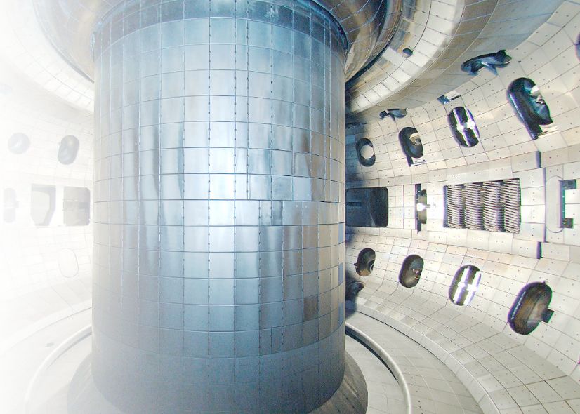
FIG. 3: (a) With vertical control algorithms, the plasma is rapidly dropped ∼ 10 cm during a jogging event. (b) Due
to the jog, the resonant q surface moves substantially through the pedestal. (c) The effects of the jog are confined to
a small edge region with width wr that contains a thin, strong current layer. Image Credit: General Atomics.
Analytical studies have shown that, during a jogging edge current impact the poloidal magnetic field through
event, toroidal current is induced in the pedestal due pri- Ampere’s law, which in turn impacts the winding ratio
marily to the compression of the plasma cross section as of magnetic field lines q = m/n and modifies the location
it travels through an inhomogeneous magnetic field39 , as of rational magnetic surfaces in the pedestal.
described further in the methods section. Changes in the Here we apply this same principle in a more intense4
jogs are large enough to influence the edge peak in Jt but
150 DIII-D #174864
f
magnetics (B)
small enough not to significantly disturb the core plasma.
(a)
Frequency (kHz)
120 This perturbation scheme is uniquely capable of investi-
gating the behavior of microinstabilities in the edge by
90
decoupling the q and ωe∗ profiles.
60 When applied in experiment, the jogs successfully pro-
30 duce clear and quantifiable differences in microinstabil-
0
ity signatures distinct from observations during natural
(b) inter-ELM periods. In figure 4(a), a magnetic spec-
n=5
Frequency (kHz)
120 n=5 trogram from high-frequency Mirnov coils is shown for
90 n=4
a time period including two natural ELM periods fol-
n=3 n=3 lowed by a large jogging perturbation. Multiple insta-
60 n=2
bilities are evident in the inter-ELM periods, but the
30 higher frequency modes at ∼ 60 kHz and ∼ 110 kHz show
0
an inverted chirping behavior after the jogging event
3 at 3700 ms. Again, local density fluctuation measure-
zp (cm)
0 ments place these modes in the plasma edge. Using
−3 Fourier analysis techniques on a set of fast magnetic
−6
diagnostics40 , the chirped modes are identified in fig-
−9 (c)
ure 4(b) as n = 3, 4 and 5 modes. For comparison, the
1.00 time dependence of the magnetic axis height (zp ), the
Ip (MA)
0.97 total plasma current Ip and the edge q profile magnitude
(q95 ) are shown during a jogging event in figure 4(c)-(e).
0.94 (d)
Notably, the robust analysis developed above can be
5.33 applied after a jogging event. Figure 5(a) shows the edge
fMTM,16/3 profile (solid curves) and the q = 16/3 loca-
q95
5.00
tion (dashed lines) as a function of post-jog time. During
4.67 (e)
the current recovery period (. 100 ms), the location of
3500 3550 3600 3650 3700 3750 3800 3850 the rational q = 16/3 surface evolves in tandem with
Time (ms) the evolution of the profile gradients after a jog-induced
ELM. The effect of this motion is that the q = 16/3 lo-
cation starts past the peak of the edge fMTM profile and
FIG. 4: (a) Magnetic fluctuations show an inverting then moves inwards over the course of ∼ 80 ms, falling
chirping behavior after a jogging event compared to slightly off the peak destabilizing frequency. In contrast
after a normal ELM. ELM times are indicated with to the growth of fMTM after a natural ELM, however,
vertical dashed lines. (b) The chirping modes are the expected MTM frequency falls after a large jogging
n = 3, 4 and n = 5 modes, shown in orange, magenta event due to the inwards motion of the magnetic sur-
and red, respectively. Additional core (black) and face. In figure 5(b), the computed decrease of fMTM,16/3
pedestal (blue) modes are also shown. The evolution of is overlayed on the n = 3 mode extracted from magnetics
the (c) magnetic axis Zp , (d) plasma current Ip and (e) measurements in figure 4(b). The time-dependent profile
edge safety factor q95 through a jogging event show the analysis matches the experimentally-observed fluctuation
direct effects of the jog. dynamics, showing strong agreement between theory and
experiment. Moreover, it is noted that the n = 3 mode
amplitude (see figure 4(a)) is strongest when the 16/3
manner with large (∼ 10 cm) and fast (< 10 ms) down- surface is best aligned with the peak of the ωe∗ profile, in
ward jogs designed to produce the largest possible per- agreement with the expectation that the electron ther-
turbations in the edge current. Figure 3(a) compares mal gradient, which peaks with ωe∗ , acts as main MTM
two equilibria before (red) and after (blue) a large jog- drive25 .
ging event. The effects of the jog on the plasma are In figure 5(c), the analysis is augmented by match-
primarily constrained to an edge region wr , which can be ing the decreasing n = 4 mode observed early in the
√
approximated as the MHD skin depth wr ∝ η, where ELM cycle after jogs. In this case, the rational surface
η is the plasma resistivity39 . As a result of the jog, the m/n = 21/4, which lies just inside of the m/n = 16/3
reconstructed q profile presented in figure 3(b) dramat- surface, shows the best alignment with the peak of the
ically changes. As expected, the radial location of the ωe∗ profile. Directly after a jog, the MTM drive on this
q = 16/3 resonant surface moves dramatically through surface is high and the mode appears in magnetic fluc-
the edge region as an effect of the jog. In figure 3(c), tuation measurements. However, as the q surface moves
we show a 2D reconstruction of the plasma current den- inwards, the drive, amplitude and frequency drop until
sity Jt for the pre-jog equilibrium, highlighting that the the n = 3 mode dominates. Power is transferred to more5
100 100 100 DIII-D #174864
(a) n=3 (b) (c)
m/n=21/4
Time since jog
80 15ms 80 80
35ms m/n=16/3
Frequency (kHz)
Frequency (kHz)
Frequency (kHz)
55ms
75ms
60 95ms 60 60
115ms fMTM
135ms
40 40 40
20 20 20
q=16/3 location
0 0 0
0.90 0.92 0.94 0.96 0.98 1.00 0 30 60 90 120 150 0 30 60 90 120 150
ψn Time since jog (ms) Time since jog (ms)
FIG. 5: The automated analysis presented in figure 2 is repeated for data averaged over several jogging cycles. (a)
Due to the current recovery after a jog, the q = 16/3 surface shifts inwards as pedestal profiles recover.
Incorporating all effects yields excellent agreement between the profile-based fMTM predictions and the (b) orange
n = 3 and (c) magenta n = 4 modes extracted from magnetic fluctuation measurements.
unstable rational surfaces during this transition through local density fluctuation data41 . Conversely, KBMs
non-linear coupling between various pedestal modes7 . (the other primary electromagnetic edge turbulence
This manifests in the magnetics measurements as a dis- candidate) rotate in the ion diamagnetic direction,
appearance of the n = 4 signature coincident with a peak which is inconsistent with the measured data.
in the n = 3 amplitude around ∼ 60 ms after the jogging
event (see figure 4(a)). Again, figure 5(c) shows excellent • Experimental transport studies show that De /χe ∼
agreement between the profile and fluctuations measure- 1/10 in the vicinity of the n = 3 and n =
ments, verifying the dynamic behavior of edge-localized 5 chirped modes. This is consistent with gy-
MTMs. We note further that the very low MTM fre- rokinetic predictions stating that pedestal MTMs
quency predicted directly after the jog (tjog = 20 ms) in should contribute predominately to electron ther-
figures 5(b) and 5(c) occurs at a time before the MTM mal transport, whereas KBMs contribute approxi-
onset and thus is not expected to produce magnetic fluc- mately equally to both electron thermal and parti-
tuations. This analysis can be reproduced to the same cle transport18 .
effect for the n = 5 modes shown in figure 4(b) and is • Finally, the modes turn on simultaneously with the
robust to changes in the background plasma across sev- saturation of ∇Te , consistent with models tying
eral DIII-D discharges, showing that minor background destabilization to the growth of pedestal gradients
plasma changes do not modify the fundamental MTM beyond a critical threshold31,42 .
behavior.
In sum, these compounding observations combined with
the novel dynamic frequency evolution described above
DISCUSSION AND OUTLOOK paint an explicit experimental picture of the existence of
MTMs in the DIII-D H-mode pedestal. Further, mea-
To support the above dynamic identification of MTMs surements showing that the associated transport is pre-
in the H-mode pedestal, we note here that additional dominantly in the electron heat channel and is closely
measurements were taken to rule out the possibility of linked to the saturation of ∇Te reinforce the established
the above dynamics being caused by other instabilities. tendency of MTMs to contribute significantly to electron
heat flux through the plasma edge.
• Large amplitudes of these modes in magnetic fluc- By regulating electron thermal transport, MTMs are
tuation measurements suggest that the modes are expected to establish limits on the maximum electron
electromagnetic in nature, eliminating considera- temperature gradients within the H-mode pedestal16 .
tion of ETGs, ITGs and TEMs. Since the pedestal contributes substantially to total
plasma pressure and fusion performance, identifying and
• The propagation of the chirped modes is deter- understanding the full impact of MTMs could have sig-
mined to be strongly in the electron diamagnetic nificant implications on the design of future pilot plan
direction, as is expected for MTMs, both through scenarios. While numerous theoretical studies have pre-
E × B profile calculations and detailed analysis of dicted the presence of these instabilities under common6
pedestal conditions, an experimental validation is re- reproduced here for convenience:
quired to build confidence in the MTM physics basis if
predictive pedestal models are to be expanded to include 1 1
ωe∗ = ky ρs cs + . (2)
the relevant effects. In this article, we experimentally Lne LTe
demonstrate the existence of edge-localized MTMs by
exploiting the time response of the plasma to vertical Here ky = nq/aρtor is the binormal wavenumber, ρtor =
√
jogs. These results validate leading analytic and numeri- Φn is the square root of the normalized toroidal mag-
cal theories18,25 and motivate the future incorporation of netic
p flux, ρs = cs /Ωi is the sound gyroradius, cs =
MTM effects into advanced predictions of the full plasma ZTe /mi is the sound speed, Ωi is the ion gyrofrequency,
performance. and the electron density and temperature gradient scale
The success of the perturbative approach applied here lengths are defined as a/Lne = (1/ne )(dne /dρtor ) and
also implies a possibility for the expansion of dynamic a/LTe = (1/Te )(dTe /dρtor ), respectively25 . The Doppler
turbulence identification to other unexplained tokamak shift ωdop is correspondingly given by:
regimes. Similar instability markers have been reported
on a wide variety of machines and scenarios6,32 , but the nEr
ωdop = , (3)
underlying physics remains largely undetermined. The RBp
analysis presented here offers a new mechanism to un-
cover explanations for these observations, potentially en- where n is the toroidal mode number, Er is the radial
abling a comprehensive perturbative study of experimen- electric field, R is the major radius and Bp is the poloidal
tal transport signatures in tokamak devices. magnetic field.
During a jogging event, the induction of current due
to the motion of the plasma through an inhomogeneous
METHODS
magnetic field can be by is described by
4π
This investigation is predicated on the accurate si- δIφwr = δψext (a) − Bθ (r0 )R0 δwr − ηJφ δt , (4)
µ0 R0
multaneous measurement of many different plasma pa-
rameters, including electron and ion densities and tem- as first reported by Artola et. al.39 . Here the change in
peratures and the equilibrium magnetic structure. The total toroidal edge current (δIφwr ) is given as a function of
Doppler-shift ωdop and electron diamagnetic frequency the local change in external magnetic flux (δψext ), the in-
ω∗e are calculated from Carbon impurity measurements homogeneous poloidal magnetic field (Bθ ), plasma com-
from charge-exchange recombination29 and electron pro- pression (δwr ) and a small resistive decay term (ηJφ δt)39 .
file measurements from Thomson scattering28 , respec- The width wr of the edge region is generally small
tively. Localized density fluctuations measurements are compared to the plasma minor radius (r0 ) such that
made with beam emissions spectroscopy in order to lo- wr /r0 p7
high enough to directly determine the poloidal mode 8 J. E. Lee, G. S. Yun, W. Lee, M. H. Kim, M. Choi, J. Lee,
numbers40 , suggesting m > 12 as found through the M. Kim, H. K. Park, J. G. Bak, W. H. Ko, and Y. S. Park,
profile analysis. Part of data analysis for this work Scientific Reports 7, 45075 (2017).
9 J. W. Connor, R. J. Hastie, H. R. Wilson, and R. L. Miller,
was performed using the OMFIT integrated modeling Physics of Plasmas 5, 2687 (1998).
framework48,49 . 10 C. Ham, A. Kirk, S. Pamela, and H. Wilson, Nature Reviews
Physics 2, 159 (2020).
11 T. E. Evans, R. A. Moyer, K. H. Burrell, M. E. Fenstermacher,
I. Joseph, A. W. Leonard, T. H. Osborne, G. D. Porter, M. J.
DATA AVAILABILITY Schaffer, P. B. Snyder, P. R. Thomas, J. G. Watkins, and W. P.
West, Nature Physics 2, 419 (2006).
12 J.-K. Park, Y. Jeon, Y. In, J.-W. Ahn, R. Nazikian, G. Park,
The data discussed and used for all figures in this ar-
J. Kim, H. Lee, W. Ko, H.-S. Kim, N. C. Logan, Z. Wang, E. A.
ticle are available from the corresponding author upon Feibush, J. E. Menard, and M. C. Zarnstroff, Nature Physics 14,
reasonable request. 1223 (2018).
13 R. D. Hazeltine, D. Dobrott, and T. S. Wang, The Physics of
Fluids 18, 1778 (1975).
14 J. F. Drake and Y. C. Lee, Physics of Fluids 20, 1341 (1977).
ACKNOWLEDGMENTS 15 P. B. Snyder, R. J. Groebner, J. W. Hughes, T. H. Osborne,
M. Beurskens, A. W. Leonard, H. R. Wilson, and X. Q. Xu,
The authors would like to especially thank D.R. Hatch Nuclear Fusion 51, 103016 (2011).
16 D. Dickinson, C. M. C. Roach, S. Saarelma, R. Scannell, A. Kirk,
and M. Curie for several helpful discussions relating to
and H. R. H. Wilson, Physical Review Letters 108, 135002
the frequency identification of MTMs, as well as W. (2012), arXiv:1110.0619.
Guttenfelder and R. Nazikian for valuable advice dur- 17 D. R. Hatch, M. Kotschenreuther, S. Mahajan, P. Valanju,
ing preparation of the manuscript. This material was F. Jenko, D. Told, T. Görler, and S. Saarelma, Nuclear Fusion
supported by the U.S. Department of Energy, Office of 56, 104003 (2016).
18 M. Kotschenreuther, X. Liu, D. R. Hatch, S. Mahajan, L. Zheng,
Science, Office of Fusion Energy Sciences, using the DIII- A. Diallo, R. Groebner, J. Hillesheim, C. Maggi, C. Giroud,
D National Fusion Facility, a DOE Office of Science F. Koechl, V. Parail, S. Saarelma, E. Solano, and A. Chankin,
user facility, under Awards DC-AC02-09CH11466, DE- Nuclear Fusion 59, 096001 (2019).
19 D. J. Applegate, C. M. Roach, J. W. Connor, S. C. Cowley,
SC0015480, DE-SC0015878 and DE-FC02-04ER54698.
This report is prepared as an account of work sponsored W. Dorland, R. J. Hastie, and N. Joiner, Plasma Physics and
Controlled Fusion 49, 1113 (2007), arXiv:1110.3277.
by an agency of the United States Government. Neither 20 H. Doerk, F. Jenko, M. J. Pueschel, and D. R. Hatch, Physical
the United States Government nor any agency thereof, Review Letters 106, 155003 (2011).
nor any of their employees, makes any warranty, express 21 W. Guttenfelder, J. Candy, S. M. Kaye, W. M. Nevins, E. Wang,
or implied, or assumes any legal liability or responsibil- R. E. Bell, G. W. Hammett, B. P. Leblanc, D. R. Mikkelsen, and
ity for the accuracy, completeness, or usefulness of any H. Yuh, Physical Review Letters 106, 155004 (2011).
22 D. Dickinson, C. M. Roach, S. Saarelma, R. Scannell, A. Kirk,
information, apparatus, product, or process disclosed, or and H. R. Wilson, Plasma Physics and Controlled Fusion 55,
represents that its use would not infringe privately owned 074006 (2013).
23 A. K. Swamy, R. Ganesh, J. Chowdhury, S. Brunner, J. Vaclavik,
rights. Reference herein to any specific commercial prod-
uct, process, or service by trade name, trademark, man- and L. Villard, Physics of Plasmas 21, 082513 (2014).
24 J. Chowdhury, Y. Chen, W. Wan, S. E. Parker, W. Guttenfelder,
ufacturer, or otherwise, does not necessarily constitute
and J. M. Canik, Physics of Plasmas 23, 012513 (2016).
or imply its endorsement, recommendation, or favoring 25 D. R. Hatch, M. Kotschenreuther, S. M. Mahajan, M. J.
by the United States Government or any agency thereof. Pueschel, C. Michoski, G. Merlo, E. Hassan, A. R. Field,
The views and opinions of authors expressed herein do L. Frassinetti, C. Giroud, J. C. Hillesheim, C. F. Maggi, C. P.
not necessarily state or reflect those of the United States von Thun, C. M. Roach, S. Saarelma, D. Jarema, and F. Jenko,
Nuclear Fusion , in press (2020), arXiv:2007.07332.
Government or any agency thereof. 26 J. Chen, D. L. Brower, W. X. Ding, Z. Yan, T. Osborne, E. Strait,
1 J.
M. Curie, D. R. Hatch, M. Kotschenreuther, X. Jian, M. R. Half-
Wesson, Tokamaks, 3rd ed. (Oxford University Press, New moon, and S. M. Mahajan, Physics of Plasmas 27, 120701 (2020).
York, 2004). 27 J. F. Drake, N. T. Gladd, C. S. Liu, and C. L. Chang, Physical
2 J. L. Tuck, Nature 233, 593 (1971).
3 L. Artsimovich, Nature 239, 18 (1972).
Review Letters 44, 994 (1980).
28 D. Eldon, B. D. Bray, T. M. Deterly, C. Liu, M. Watkins, R. J.
4 F. Wagner, G. Fussmann, T. Grave, M. Keilhacker, M. Kornherr,
Groebner, A. W. Leonard, T. H. Osborne, P. B. Snyder, R. L.
K. Lackner, K. Mccormick, E. R. Muller, A. Stabler, G. Becker, Boivin, and G. R. Tynan, Review of Scientific Instruments 83,
K. Bernhardi, U. Ditte, A. Eberhagen, O. Gehre, J. Gernhardt, 10E343 (2012).
G. V. Gierke, E. Glock, O. Gruber, G. Haas, M. Hesse, G. Janes- 29 C. Chrystal, K. H. Burrell, B. A. Grierson, S. R. Haskey, R. J.
chitz, F. Karger, S. Kissel, O. K1qber, G. Lisitano, H. M. Groebner, D. H. Kaplan, and A. Briesemeister, Review of Scien-
Mayer, D. Meisel, V. Mertens, H. Murrnann, W. Poschenrieder, tific Instruments 87, 11E512 (2016).
H. Rapp, H. Rohr, F. Ryter, F. Schneider, G. Siller, P. Smeul- 30 C. P. Perez, H. R. Koslowski, T. C. Hender, P. Smeulders,
ders, F. Soldner, E. Speth, K.-H. Steuer, Z. Szymanski, and A. Loarte, P. J. Lomas, G. Saibene, R. Sartori, M. Becoulet,
O. Vollmer, Physical Review Letters 53, 15 (1984). T. Eich, R. J. Hastie, G. T. Huysmans, S. Jachmich, A. Regis-
5 K. H. Burrell, Physics of Plasmas 4, 1499 (1997).
6 A. Diallo and F. M. Laggner, Plasma Physics and Controlled
ter, and F. C. Schüller, Plasma Physics and Controlled Fusion
46, 61 (2004).
Fusion 63, 013001 (2021). 31 A. Diallo, R. J. Groebner, T. L. Rhodes, D. J. Battaglia, D. R.
7 A. Diallo, J. Dominski, K. Barada, M. Knolker, G. J. Kramer,
Smith, T. H. Osborne, J. M. Canik, W. Guttenfelder, and P. B.
and G. McKee, Physical Review Letters 121, 235001 (2018).8 Snyder, Physics of Plasmas 22, 056111 (2015). 40 E. J. Strait, Review of Scientific Instruments 77, 023502 (2006). 32 F. M. Laggner, A. Diallo, M. Cavedon, and E. Kolemen, Nuclear 41 G. McKee, R. Ashley, R. Durst, R. Fonck, M. Jakubowski, Materials and Energy 19, 479 (2019). K. Tritz, K. Burrell, C. Greenfield, and J. Robinson, Review of 33 A. W. Degeling, Y. R. Martin, J. B. Lister, L. Villard, V. N. Scientific Instruments 70, 913 (1999). Dokouka, V. E. Lukash, and R. R. Khayrutdinov, Plasma Physics 42 A. Diallo, J. W. Hughes, M. Greenwald, B. LaBombard, E. Davis, and Controlled Fusion 45, 1637 (2003). S.-g. Baek, C. Theiler, P. B. Snyder, J. Canik, J. Walk, 34 P. T. Lang, A. W. Degeling, J. B. Lister, Y. R. Martin, P. J. T. Golfinopoulos, J. Terry, M. Churchill, A. Hubbard, M. Porko- Mc Carthy, A. C. Sips, W. Suttrop, G. D. Conway, L. Fat- lab, L. Delgado-Aparicio, M. L. Reinke, A. White, and the Alca- torini, O. Gruber, L. D. Horten, A. Herrmann, M. E. Manso, tor C-Mod team, Physical Review Letters 112, 115001 (2014). M. Maraschek, V. Mertens, A. Mück, W. Schneider, C. Sihler, 43 Z. Xing, D. Eldon, A. O. Nelson, M. A. Roelofs, W. J. Eggert, W. Treutterer, and H. Zohm, Plasma Physics and Controlled Fu- O. Izacard, A. Glasser, N. Logan, O. Meneghini, S. P. Smith, sion 46, L31 (2004). R. Nazikian, and E. Kolemen, Fusion Engineering and Design 35 S. P. Gerhardt, J. W. Ahn, J. M. Canik, R. Maingi, R. Bell, 163, 112163 (2021). D. Gates, R. Goldston, R. Hawryluk, B. P. Le Blanc, J. Menard, 44 R. J. Bickerton, J. W. Connor, and J. B. Taylor, Nature Physical A. C. Sontag, S. Sabbagh, and K. Tritz, Nuclear Fusion 50, Science 229, 110 (1971). 064015 (2010). 45 J. Breslau, M. Gorelenkova, F. Poli, J. Sachdev, and X. Yuan, 36 J. Kim, Y. M. Jeon, W. W. Xiao, S. W. Yoon, J. K. Park, G. S. DOE CODE (2018). Yun, J. W. Ahn, H. S. Kim, H. L. Yang, H. K. Kim, S. Park, J. H. 46 O. Izacard, E. Kolemen, O. Meneghini, D. P. Eldon, and M. V. Jeong, M. Jung, G. H. Choe, W. H. Ko, S. G. Lee, Y. U. Nam, Umansky, 60th Annual Meeting of the APS Division of Plasma J. G. Bak, K. D. Lee, H. K. Na, S. H. Hahn, P. H. Diamond, Physics 53, 11 (2018). T. Rhee, J. M. Kwon, S. A. Sabbagh, Y. S. Park, H. K. Park, 47 A. O. Nelson, Z. A. Xing, O. Izacard, F. M. Laggner, and E. Kole- Y. S. Na, W. C. Kim, and J. G. Kwak, Nuclear Fusion 52, 114011 men, Nuclear Materials and Energy 26, 100883 (2021). (2012). 48 O. Meneghini, S. P. Smith, L. L. Lao, O. Izacard, Q. Ren, J. M. 37 E. De La Luna, I. T. Chapman, F. Rimini, P. J. Lomas, Park, J. Candy, Z. Wang, C. J. Luna, V. A. Izzo, B. A. Grierson, G. Saibene, F. Koechl, R. Sartori, S. Saarelma, R. Albanese, P. B. Snyder, C. Holland, J. Penna, G. Lu, P. Raum, A. McCub- J. Flanagan, F. Maviglia, V. Parail, A. C. Sips, and E. R. Solano, bin, D. M. Orlov, E. A. Belli, N. M. Ferraro, R. Prater, T. H. Nuclear Fusion 56, 026001 (2016). Osborne, A. D. Turnbull, and G. M. Staebler, Nuclear Fusion 55, 38 N. Wu, S. Y. Chen, X. M. Song, M. L. Mou, J. Huang, Z. T. 083008 (2015). Wang, C. J. Tang, X. Song, F. Xia, and M. Jiang, Physics of 49 N. C. Logan, B. A. Grierson, S. R. Haskey, S. P. Smith, Plasmas 24, 092507 (2017). O. Meneghini, and D. Eldon, Fusion Science and Technology 74, 39 F. J. Artola, G. T. Huijsmans, M. Hoelzl, P. Beyer, A. Loarte, 125 (2018). and Y. Gribov, Nuclear Fusion 58, 096018 (2018).
You can also read