Plasma-liquid synthesis of silver nanoparticles and their antibacterial and antifungal applications - IOPscience
←
→
Page content transcription
If your browser does not render page correctly, please read the page content below
Materials Research Express

PAPER • OPEN ACCESS

Plasma-liquid synthesis of silver nanoparticles and their antibacterial and
antifungal applications
To cite this article: Urooj Shuaib et al 2020 Mater. Res. Express 7 035015

View the article online for updates and enhancements.

                                This content was downloaded from IP address 176.9.8.24 on 24/03/2020 at 13:45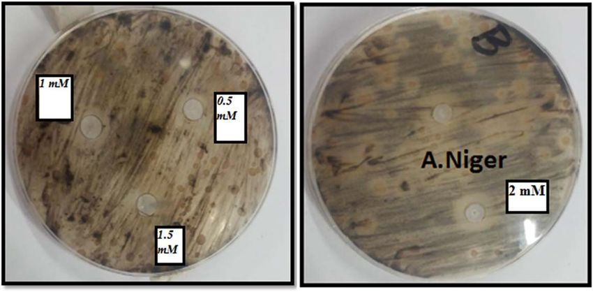
Mater. Res. Express 7 (2020) 035015 https://doi.org/10.1088/2053-1591/ab7cb6
PAPER
Plasma-liquid synthesis of silver nanoparticles and their
OPEN ACCESS
antibacterial and antifungal applications
RECEIVED
1 November 2019
Urooj Shuaib1, Tousif Hussain1 , Riaz Ahmad2, Muhammad Zakaullah3, Farrukh Ehtesham Mubarik1,
REVISED
26 February 2020
Sidra Tul Muntaha1 and Sana Ashraf1
1
Centre for Advanced Studies in Physics (CASP), GC University Lahore, Pakistan
ACCEPTED FOR PUBLICATION 2
4 March 2020 Department of Physics, GC University Lahore, Pakistan
3
Rafi Chaudhry Chair, Centre for Advanced Studies in Physics (CASP), GC University Lahore, Pakistan
PUBLISHED
16 March 2020 E-mail: tousifhussain@gmail.com and tousifhussain@gcu.edu.pk
Keywords: micro plasma, silver nanoparticles, antibacterial activity, antifungal activity
Original content from this
work may be used under
the terms of the Creative
Commons Attribution 4.0
licence. Abstract
Any further distribution of Silver nanoparticles are synthesized by employing argon atmospheric pressure DC microplasma
this work must maintain
attribution to the
technique. Specifically, the variation in fructose molar concentration is investigated for its role in the
author(s) and the title of size of nanoparticles. The 2 mM molar concentration of fructose is optimum for the production of
the work, journal citation
and DOI. silver nanoparticles in the range ‘50±10 nm’. Antibacterial and antifungal action demonstrates that
silver nanoparticles with small size and larger surface areas are very effective against bacteria and
fungus.
1. Introduction
Noble metal nanoparticles owing to their contribution in a variety of fields, including medical [1, 2], electronics
[3, 4], plasmonics [5–7], catalysis [8, 9] and optics [10, 11] are currently capturing the attention of researchers.
Noble metal nanoparticles attain amazing capabilities when their electrical, optical, and chemical properties are
varied by tuning their size, shape, composition, and local environment [12]. Presently, efforts are underway for
the synthesis of noble metal nanoparticles of the desired size. Various applications of the nanoparticles are also
actively investigated.
Silver nanoparticles have been reported to be functional due to their various applications including antiviral
activity [13], antibacterial activity [14], antifungal activity [15], catalytic applications [16], plasmon resonance
[17–19], remedial applications [20, 21], diagnostic [22, 23] and conductive applications [24, 25]. Different
research groups implemented a wide range of methods for the synthesis of silver nanoparticles, including
physical [26, 27], chemical [28, 29], and biological methods [30, 31]. To use these methods, expensive vacuum
systems, pricey technology, more time consumption and toxic reducing agents are required. The plasma-liquid
interactions technique for the synthesis of nanoparticles is comparatively new. Different configurations of these
methods depending upon power sources and electrodes have been used for the growth of silver nanoparticles
[32–34].
One of these configurations is Atmospheric Pressure DC Microplasma which is used in the current research
for the synthesis of silver nanoparticles. Atmospheric Pressure DC Microplasma is the simplistic,
environmentally acceptable, fast, and cost effectual plasma-liquid interaction system. Microplasmas are non-
Local Thermodynamic Equilibrium (non-LTE), high-pressure discharges that can be handled at room
temperature, atmospheric pressure, low rate of gas flow, moderate current and voltage [35–37]. Some
noteworthy characteristics of microplasma which make them appreciable for the growth of nanoparticles
include high-pressure chemistry, facile reactor geometry, uninterrupted flow and self accumulation of
nanostructures formed by microplasma methods, high radical densities [38–40] and most importantly the
connection of microplasma with solutions [41, 42].
One of the major issues is the aggregation of nanoparticles after their production. As a result, nonuniformity
is observed in the size of silver nanoparticles, which may affect their properties. It is important to tune the size of
© 2020 The Author(s). Published by IOP Publishing Ltd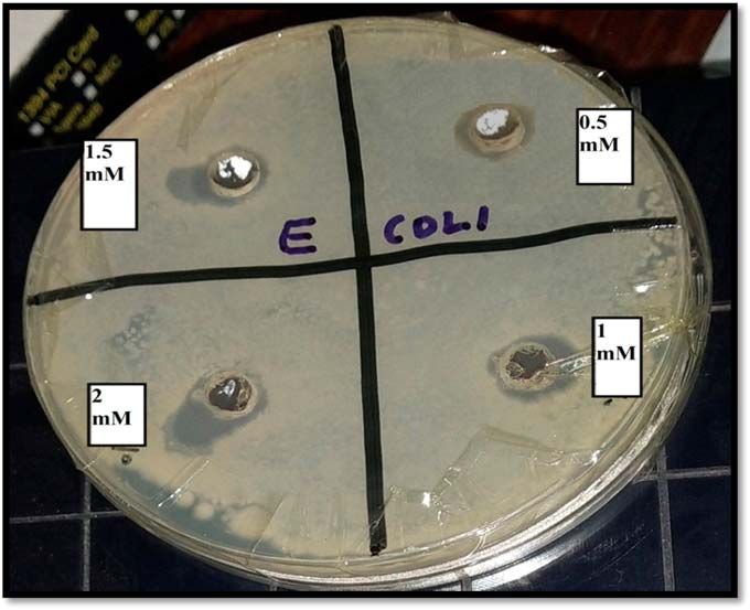
Mater. Res. Express 7 (2020) 035015 U Shuaib et al
Figure 1. Schematic diagram of microplasma setup.
nanoparticles. To achieve this objective, we tried the variation in molar concentration of the stabilizer fructose,
keeping the silver nitrate molar concentration constant so that the effect of fructose is visible. Previously, silver
nanoparticles have been prepared by different groups using the microplasma technique [43–47]. They used
various stabilizers to adjust the size and composition of the nanoparticles. Some of them also performed the
antibacterial activity of silver nanoparticles. To the best of our knowledge, the antifungal activity of silver
nanoparticles prepared to employ the microplasma technique has not been reported yet. We study the effect of
size and dispersion of nanoparticles on their antibacterial and antifungal activity.
2. Experimental section
Experimental setup and parameters are given in figure 1 and table 1, respectively. 50 ml electrolyte solutions are
prepared in deionized water using the same silver nitrate (AgNO3) molar concentration (5 mM) and fructose
(C6H12O6) (supplied by ‘Alfa Aesar’) with varying molar concentrations (0.5 mM-2 mM). Copper wire
(diameter 1.75 mm) immersed in 50 ml electrolyte solution acts as anode and stainless-steel cathode needle
(0.64 mm outer diameter, 0.34 mm internal diameter, length 7.5 mm) positioned 0.75 mm over the solution
surface is used as the cathode. Anode and cathode are adjusted 2±0.1 cm away from each other. ‘Matsusada’
stabilized negative DC power supply is used to initiate and sustain microplasma at 600 V. Hasting mass flow
meter and controller are utilized to transfer argon gas at a flow rate of 100 sccm through stainless steel needle for
plasma formation. Due to the generation of discharge, the gap between cathode and solution surface becomes
conductive and the path is completed for electrochemistry to take place. The current is kept constant at a value of
15 mA throughout the experiment. Plasma is stabilized by a ballast resistor (Resistance: 8 kΩ). Plasma and
solution interaction time is set at 30 min To analyze the influence of fructose molar concentration on size and
dispersion of silver nanoparticles, four experiments are performed by varying the molar concentration of
fructose from 0.5 mM to 2 mM.
Electrolyte solution containing silver nitrate is dissociated into Ag+ cations and NO− 3 anions
(AgNO3→Ag++NO− 3 ). When microplasma comes in contact with the solution, the active radicals and
electrons from plasma reduce the Ag+ cations into silver nanoparticles (Ag++e−→Ag). The formation of
silver nanoparticles is witnessed by a change in solution color (brown).
Agar well diffusion method is used to investigate the activity of silver nanoparticles as Antifungal and
Antibacterial agent. Antifungal activity of silver nanoparticles is investigated against Aspergillus Niger fungus.
Whereas the Antibacterial effectiveness of silver nanoparticles is investigated against two bacteria (gram-positive
and gram-negative). A 100 μl solution containing bacterial/fungal culture is spread on the plates in which
nutrient agar is filled. Wells of diameter (6 mm) are cut in the agar medium and 20 μl solution of silver
nanoparticles samples with (0.5 Mm to 2 mM) fructose molar concentration are poured in the wells using a
2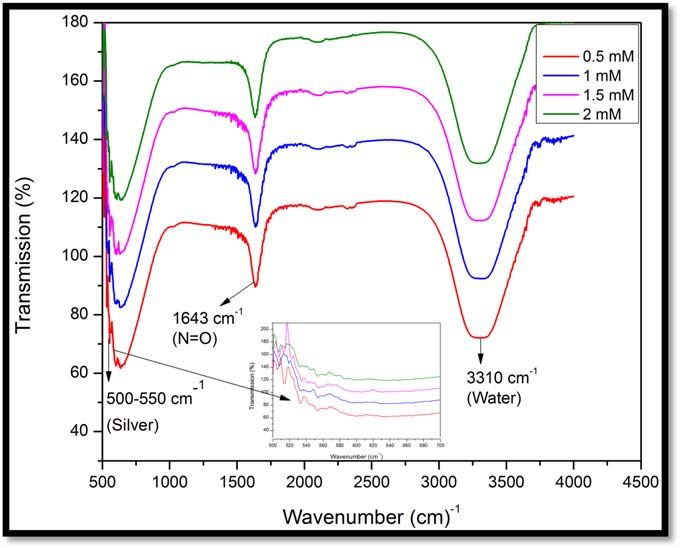
Mater. Res. Express 7 (2020) 035015
Table 1. Experimental parameters to study the effect of fructose.
3
No Molar concentration of silver Molar concentration of fructose Volume of solu- Discharge cur- Distance between anode Needle-solution dis- Time dura- Argon flow
of exp nitrate (AgNO3) (mM) (C6H12O6) (mM) tion (ml) rent (mA) and cathode (cm) tance (mm) tion (min) rate (sccm)
1 5 0.5 50 15 2±0.1 0.75 30 100
2 5 1 50 15 2±0.1 0.75 30 100
3 5 1.5 50 15 2±0.1 0.75 30 100
4 5 2 50 15 2±0.1 0.75 30 100
U Shuaib et al
Mater. Res. Express 7 (2020) 035015 U Shuaib et al
Figure 2. The optical emission spectrum of microplasma at 15 mA current and 100 sccm argon flow rate.
micropipette. For the antibacterial investigation, the plates are incubated at 37 °C whereas for antifungal
investigation the plates are incubated at 30 °C for 24 h. Finally, the diameters of inhibition zones are measured.
3. Characterization techniques
Different characterization techniques are employed for the examination of synthesized silver nanoparticles.
Optical Emission Spectroscopy (Ocean Optics HR 4000) is used to detect species responsible for the growth of
silver nanoparticles. The effect of fructose on the morphology and composition of silver nanoparticles is
examined by Scanning Electron Microscope (JEOL JSM-6480 LV), UV-Visible Spectroscopy (Ocean Optics HR
4000), x-ray Diffraction (Phillips X’Pert PRO) and Fourier Transform Infrared Spectroscopy (IR Prestige-21).
The action of silver nanoparticles against bacteria and fungus is determined using the well diffusion method.
4. Results and discussion
4.1. Optical emission spectrum
Optical Emission Spectrum of microplasma is recorded in order to investigate the species which are present
during the synthesis of nanoparticles. Lines appearing at 306 nm and 308 nm represent OH radicals while other
lines in the spectrum indicate the second positive system of nitrogen (shown in figure 2). When microplasma is
operated at atmospheric pressure, ultraviolet radiations are generated because some fraction of oxygen and
nitrogen gases from the air is mixed with argon. Interaction of plasma with the solution at atmospheric pressure
provides active chemical species and radicals [48]. Water molecules dissociate into OH radicals and atomic
hydrogen due to UV radiation. The OH radicals are powerful reducing agents. The following chemical reaction
is involved in the process of dissociation.
UV + H2 O H + OH (1)
The energetic electrons from microplasma can also interact with atomic hydrogen and get attached to it. This
process results in the formation of H− which is also a reducing specie but it is short-lived. One of the most
important reducing agent formed in microplasma discharge is hydrogen peroxide (H2O2). OH radicals are
responsible for the production of H2O2 [48, 49]. The reaction of H2O2 molecules occurs with Ag+ for the
nucleation of Ag nanoparticles.
H2 O2 + 2Ag + 2Ag + 2H+ + O2 (2)
The amount of H2O2 molecules is strongly dependent upon UV radiation intensity, a number of OH radicals
and energetic electrons produced. Electrons can also act as a reducing agent in the synthesis of nanoparticles.
When AgNO3 is dissolved in water, it dissociates into Ag+ and NO− 3 . When microplasma comes in contact with
the solution, electrons reduce the Ag+ ions to form silver nanoparticles.
e- + Ag + Ag (3)
4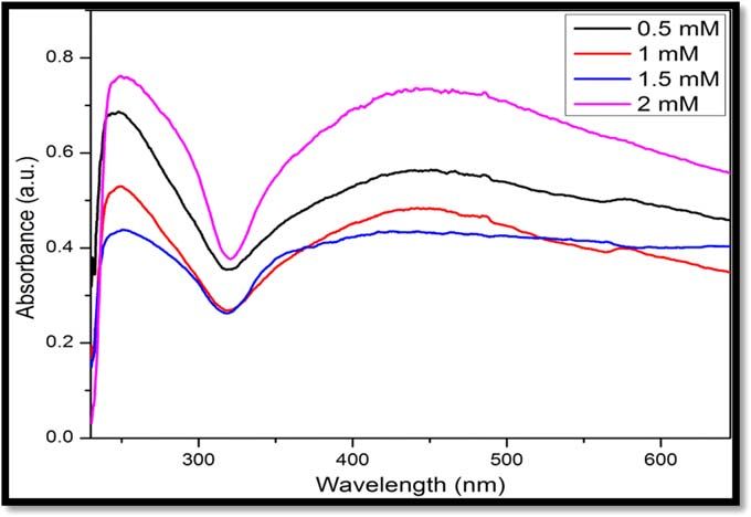
Mater. Res. Express 7 (2020) 035015 U Shuaib et al
Figure 3. (a)–(d) SEM images of the samples with various molar concentrations of fructose 0.5 mM, 1 mM, 1.5 mM and 2 mM
respectively (e) 2 mM sample at higher magnification.
4.2. SEM analysis
Scanning Electron Microscopy is done to study the morphology of the silver nanoparticles. For SEM analysis,
5 μl volume of as-prepared silver nanoparticles solution is dropped on a silicon wafer using a micropipette and
then dried at room temperature. Figures 3(a)–(e) shows the SEM images of the synthesized silver nanoparticles.
The SEM images of silver nanoparticles prepared from solution with 0.5 mM and 1 mM molar concentration of
fructose (figures 3(a), (b)), show microparticles with non-uniformity in size. These microparticles may be
agglomerated nanoparticles. By increasing the molar concentration of fructose to 1.5 mM, silver nanoparticles
formed are found to be less agglomerated. Circular, spherical and very well dispersed nanoparticles with no
agglomerates when molar concentration of fructose in solution is increased to 2 mM, having a size of
50±10 nm. The reason for the agglomeration of nanoparticles is their large surface energies associated with
their large surface areas; therefore, their surface atoms become unstable. So, these surface atoms agglomerate by
making bonds with the surface atoms of adjacent particles for stabilization. Due to the addition of a stabilizer,
there is a counterbalance of the surface energy of nanoparticles and it creates a region with less surface energy.
Particles can then be easily distinguished because they are separated. We can conclude that plasma having
energetic electrons and reactive species is working as a reducing agent to produce nanoparticles and an
appropriate amount of fructose is overcoming the problem of agglomeration. Table 2 shows the estimated sizes
of silver nanoparticles calculated by using SEM images at different molar concentrations of fructose. Size
decreases with increasing fructose concentration up to 2 mM. With the decrease in the size of silver
nanoparticles, their surface area to volume ratio increases and they become more reactive [50]. The variation in
surface area to volume ratio with a change in the size of silver nanoparticles is also summarized in table 2.
5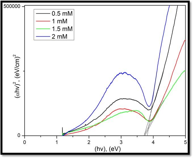
Mater. Res. Express 7 (2020) 035015 U Shuaib et al
Table 2. Comparison of size and surface area to volume ratio of silver
nanoparticles at different molar concentrations of fructose.
Fructose molar con- Surface area/volume
(m−1) (4πr2/ 3 pr 3)
4
centration (mM) Average size (nm)
0.5 agglomerates Agglomerates
1 180±10 nm 3.3×10⁷
1.5 150±10 nm 4×10⁷
2 50±10 nm 1.2×10⁸
Figure 4. UV absorbance spectra at various molar concentrations of fructose (0.5 mM to 2 mM).
4.3. Band gap energies
Figure 4 shows the UV visible absorbance spectra of silver nanoparticles synthesized by using microplasma in a
solution of 5 mM AgNO3 with various molar concentrations of fructose. A quartz cuvette of optical path length
is used to measure the spectra of the solution containing nanoparticles. The formation of silver nanoparticles in
the solution is indicated by two surface plasmon resonance bands due to the mutual vibration of free electrons at
the surface of silver nanoparticles with incoming light photons [51–53]. The first band from 240–300 nm is
because of out-of-plane quadrupolar resonance, whereas the second-wide absorbance band from 325 to 645 nm
can be attributed to in-plane dipole resonance [14, 54, 55]. The observed absorbance band shows a characteristic
surface plasmon resonance of silver nanoparticles [56, 57].
Secondary peaks in the UV spectrum show the agglomeration of particles [58]. The minor broad secondary
peak at wavelength 580 nm can be observed in the spectra of samples with 0.5 mM to 1.5 mM fructose molar
concentration and such peak is missing in the sample with 2 mM fructose molar concentration. No secondary
peak can be referred to as the formation of stabilized silver nanoparticles hence preventing any agglomeration at
2 mM fructose molar concentration, which indicates that at 2 mM concentration, fructose effectively restrains
silver nanoparticle from aggregation.
Bandgap energy of silver nanoparticles is also observed by Tauc Plot (a graph between (αhυ)2 and hυ), as
shown in figure 5 for direct bandgap of silver nanoparticles. The point where the line touches the x-axis
represents bandgap energy according to the following equation [59, 60].
ahu = B (hu - E g )n (4)
Where α is the absorption coefficient, Eg is the bandgap energy and B is constant, n is the value which depends
upon transition and is 1/2 for allowed direct bandgap [61]. The absorption coefficient α can be determined from
the relation,
I
A= = e-ad (5)
I0
It can also be evaluated using relation derived from Beer–Lambert’s relation
A
a = 2.303 (6)
d
Where A is the absorbance from the UV spectrum and d is cuvette path length [60–62].
6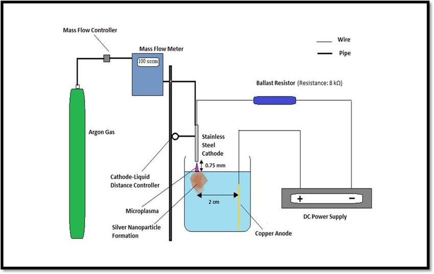
Mater. Res. Express 7 (2020) 035015                                                                                         U Shuaib et al

   Figure 5. Tauc plot of various samples with varying fructose molar concentrations (0.5 mM to 2 mM) to find direct bandgap of silver
   nanoparticles.

   Figure 6. FTIR spectra of silver nanoparticles at various molar concentrations of fructose (0.5 mM to 2 mM).

    The values of direct bandgap energies of silver nanoparticles obtained from tauc plots of samples are higher
than the bandgap energy value of bulk silver. Our band gap energy values are agreed well with the values reported
by Das et al [63]. The reason for large bandgap energy values of silver nanoparticles as compared to bulk silver is
that nanoparticles are made up of a small number of atoms. In this way, the overlapping of energy levels
decreases which result in the reduction of bandwidth and increment in energy between valance and conduction
band. Conversely, bulk contains a large number of atoms due to which overlapping of energy levels increases
which results in an increase of band size and decrease of energy between valance and conduction band.

4.4. FTIR analysis
Investigation of the chemical composition of silver nanoparticles and their surrounding environment is done by
FTIR spectroscopy in the range 500 to 4000 cm−1 (as shown in figure 6). The FTIR spectra show band around
500–550 cm−1 which confirms the presence of stretching mode for silver. The inset graph clearly shows the
number of peaks in the above-mentioned range. Impurity N=O due to silver nitrate (AgNO3) is also indicated
by the transmission peak at 1643 cm−1. The broad peak at 3310 cm−1 points out the presence of water. The FTIR
spectra of samples with 0.5 mM to 2 mM fructose molar concentration exhibit no variation [14, 64].

                                                        7
Mater. Res. Express 7 (2020) 035015 U Shuaib et al
Figure 7. XRD graph of the sample with molar concentration of fructose 2 mM.
Table 3. Estimation of crystallite size and d spacing.
2θ (degree) Planes d Spacing (nm) Crystallite size (nm)
37.906 (111) 0.2372 28.5±1.4
44.125 (200) 0.2051 25.6±1.3
64.011 (220) 0.1451 18.9±1
77.187 (311) 0.1235 19.4±1
4.5. XRD analysis
Figure 7 shows the XRD of the sample with 2 mM fructose molar concentration which is carried out to identify
the phase of crystalline silver nanoparticles. Brags reflections analogous to crystallographic orientations (111),
(200), (220) and (311) can be seen which justify the presence of silver. Broadening in peaks shows that the size of
particles is in the range of nanoscale [64]. XRD graph has no extra peaks means there is no significant amount of
impurity in the sample. All peaks are representing face-centered cubic pure silver metal. Four peaks at 2θ values
of 37.906°, 44.125°, 64.011°, and 77.187° correspond to lattice planes (111), (200), (220) and (311) match with
JCPDS, silver file No. 04–0783 standard powder diffraction card. The peaks with strong intensity exhibit that
particles are having a good level of crystallinity. Intense (111) reflection is observed in fcc materials. It is
concluded from XRD results that synthesized silver nanoparticles are face-centered cubic.
The experimental values of ratios between intensities of diffraction peaks (200) and (111), (220) and (111) are
0.45 and 0.13 respectively and these values are comparable to the conventional values (0.40 and 0.25) of above-
mentioned diffraction peaks [64]. The Debye–Scherrer formula is used to estimate the crystallite size D (nm)
[65].
kl
D= (7)
bcosq
Here λ=0.1541 nm, β represents FWHM in radians, θ is an angle of diffraction and k=0.9 for spherical
nanoparticles [66]. Bragg’s law is used to calculate inter-planar spacing d between the atoms [67]. Table 3 shows
the calculation of crystallite size and d spacing.
2d sin q = nl (8)
Where λ=0.1541 nm is x ray wavelength, θ is angle of diffraction, n is order of diffraction.
The more intense peak (111) is selected to extract information from the XRD data. The formulae shown in
equations (9) and (10) are used for experimental and theoretical calculations of lattice constant respectively (as
shown in table 4) [64, 68, 69].
a = dhkl h2 + k 2 + l2 (9)
8Mater. Res. Express 7 (2020) 035015 U Shuaib et al
Table 4. Representing theoretical and
experimental values of lattice constant.
Theoretical value Experimental value
4.07 Å 4.10 Å
Table 5. The crystallinity index.
Dsem (nm) Dxrd (nm) Icry
∼50 28.5 ∼1.8
Where dhkl is the inter-planar spacing.
4
a= ´r (10)
2
Where r=144 p.m for silver.
A dislocation is one of the types of defects in crystal structures. The existence of dislocations affects the
properties of materials to a great extent. Dislocations existing in the material hinder the movement of each other.
Thus, a large dislocation density causes large hardness. Chen and Hendrikson by measuring dislocation density
and hardness of the number of silver crystals discovered that crystals having large dislocation density were
stiff [68].
The equation (11) is used to determine the dislocation density of the sample with 2 mM molar concentration
of fructose [64–69].
15b cos q
Dislocation density = (11)
4aD
Where β is FWHM in radians, θ is diffraction angle, ‘a’ represents lattice constant and D is the crystallite size in
nm. The dislocation density in a sample is found to be 15×1014 m−2. Our dislocation density value matches
with the Shahjahan et al [69] reported value.
The variance in lattice constant of silver nanoparticles over the bulk causes intrinsic stress in nanoparticles.
The formula to measure this intrinsic stress is as follows
Y (a - a 0)
s= (12)
2ga o
Where Y=Young’s modulus of Ag =83 GPa, ao =standard bulk lattice constant=0.408 nm, a=measured
value of lattice constant =0.410 nm and γ=Poison’s ratio for silver =0.37. The value of intrinsic stress in our
case is 0.55 GPa which shows the nature of stress is tensile.
It is well known that sharper peaks of XRD pattern demonstrate that material is highly crystalline. The
crystallinity of the material [64, 68] is found by comparing the particle size from our XRD data and SEM results.
The SEM results show that the average particle size for this sample is 50 nm and the crystallite size calculated
from the Debye–Scherrer formula is 28.5 nm. The equation for crystallinity index is
Dsem
I cry = (13)
Dxrd
Where Icry is crystallinity index, Dsem and Dxrd is particle size from SEM and XRD, respectively. For crystalline
material, the index of crystallinity should be greater than 1. Value of crystallinity index in our case (as shown in
table 5) is greater than 1 which shows that material is crystalline having well-indexed fcc structure.
Specific surface area (SSA) is defined as surface area (SA) per mass. The specific surface area is the value that
determines the material type and its properties. It has significant importance in heterogeneous catalysis, surface
reactions and adsorption. Nanoparticles are more reactive than other particles because they have large surface
areas. The equation used to calculate specific surface area is
6 ´ 103
Specific surface area = (14)
D p .r
Where ρ=density of silver =10.5 g/cm3, Dp=particle size. The specific surface area value for our sample is
24m2/g. These results are similar to the value of specific surface area reported by Mingru et al [70].
9Mater. Res. Express 7 (2020) 035015 U Shuaib et al
Figure 8. Zones of inhibition against bacillus subtilis for samples with varying fructose molar concentrations (0.5 mM to 2 mM).
Figure 9. Zones of inhibition against E. coli for different samples with varying fructose molar concentrations (0.5 mM to 2 mM).
4.6. Antibacterial and antifungal activity of silver nanoparticles
Bacillus Subtilis is gram-positive bacteria usually found in soil and human gastrointestinal tracks. It can cause
bacteremia, endocarditis and infections of ear, eyes, wounds, respiratory, urinary and gastrointestinal tracts.
Gram-positive bacteria have a cell wall that is made up of peptidoglycan thick layer, comprising of
polysaccharide chains linked to each other by short peptides, as a result, they have a very stiff structure in which
silver nanoparticles feel difficulty in their diffusion [71, 72].
E. coli is gram-negative bacteria usually found in the surroundings, foodstuff and intestines of animals and
people. It can cause urinary tract infections, pneumonia, respiratory sickness and neonatal meningitis [73].
Figures 8 and 9 show the antibacterial activity of silver nanoparticles against Bacillus Subtilis and E. coli
respectively. In the present study, it is observed that the effect of the increasing amount of fructose results in the
production of smaller silver nanoparticles. These nanoparticles are found to be more reactive due to their small
size and large surface areas. Zones of inhibition for both bacteria are summarized in table 6.
It can be seen that there is an increase in inhibition zone with increasing fructose concentration which is
attributed to the decrement in nanoparticle size due to reduction in agglomeration by the introduction of
fructose as a stabilizer.
10Mater. Res. Express 7 (2020) 035015 U Shuaib et al
Table 6. Zones measured against gram positive, gram negative bacteria and
fungus.
Aspergillus
Sample Bacillus subtilis E. coli Niger
0.5 mM 15±1 mm 10±1 mm 9±1 mm
1 mM 14±1 mm 11±1 mm 9±1 mm
1.5 mM 14±1 mm 13±1 mm Not clear
2 mM 15±1 mm (clearer 15±1 mm 14±1 mm
zone as compared to
0.5 mM sample)
The means of the antibacterial effects of silver are not very well defined. Silver nanoparticles can interact with
compounds comprising of phosphorous e.g. DNA. The available surface area of the silver nanoparticle which
interacts with the cell membrane of bacteria may be responsible for the toxic effects of silver nanoparticles on
bacteria. Smaller particles with large surface areas show more efficient antibacterial effects as compared to larger
ones. Ag nanoparticles release Ag+ ions and release rate increases with the decrement in the size of particles as
reported by Sotiriou et al [74]. Silver nanoparticles contain silver ions, which interact with DNA. DNA becomes
condensed and loses its ability to replicate, it also results in the death of bacteria [75]. Very fine nanoparticles less
than 10 nm release more Ag+ ions thus they show more toxic behavior towards bacteria and particles greater
than 10 nm size have low concentrations of Ag+ ions and these particles directly lead to the death of bacteria
[74]. Different reasons have been reported by research groups for the toxicity of silver nanoparticles to bacteria.
Some investigations have stated that negatively charged cell membranes and positively charged nanoparticles
have electrostatic interactions between each other thus Ag+ ions may be found to be critical for the antibacterial
activity of silver [76].
Production of reactive oxygen species such as oxygen superoxide which are formed on the surfaces of silver
nanoparticles has been accounted as the primary basis of toxic activity of silver nanoparticles. According to
various studies, higher concentrations of reactive oxygen species are examined in the cells dealing with silver
nanoparticles. Reactive oxygen species are naturally developed by the cells that show a respiratory action.
Photooxidation of water in the existence of catalysts (silver nanoparticles) is also responsible for the production
of these species and due to these species, cells suffer oxidative stresses that result in the inactivation of bacterial
cells [77]. Siva Kumar also reported that oxygen gets attached with silver and form R-S-S-R bonds after reacting
with sulfhydryl –S-H groups on cell walls and thus stops the respiration to cause the death of cells [78, 79]. In
another report, it is also observed that the presence of (111) plane and nano-size combine to enhance the
biocidal properties. The diffraction peak with high intensity at angle 37° observed in our sample is the
representative peak of (111) plane which directly interacts with the bacterial surface. The reactivity of silver is
enhanced by these high-atom density planes [80].
The antifungal activity of silver nanoparticles (shown in figure 10) is also investigated. Aspergillus Niger is
used which is common specie of genus Aspergillus. It is usually found in the form of black mold disease on
different fruits and vegetables and can contaminate food. It is one of those fungi which are not deadly but it can
cause allergic reactions and general sickness. This fungus is reproduced by the occurrence of asexual spores
named as conidia. These fungal spores are defended by means of the rigid cell wall so their inactivation is
challenging. These spores oppose desiccation and support dispersion, which permits the survival of Aspergillus
Niger for long time periods even in severe environmental circumstances. Spore damage is related to cell walls
distraction with the consequent outflow of cytoplasmic content leading to the death of cells [81]. The zone of
inhibition is given in table 6 and it is observed that 2 mM fructose molar concentration sample exhibits a clear
zone due to more reactive silver nanoparticles.
5. Conclusions
The microplasma technique is a comparatively easy and reliable technique for the synthesis of silver
nanoparticles because heavy vacuum systems and equipment are not required. It is also a user-friendly,
nontoxic, less time-consuming method. It is concluded that 2 mM fructose molar concentration is found to be
an appropriate amount for the reduction of agglomeration along with the production of relatively small and well
dispersed silver nanoparticles with uniform sizes. Optical Emission Spectrum confirms that reactive species
from plasma including OH radicals, H2O2 molecules and electrons reduce the metal ions into nanoparticles.
Plasma itself is a reducing agent in this technique. SEM indicates that fructose is acting as a stabilizer and is
helpful to lessen the agglomeration of silver nanoparticles. UV spectra show the absorbance band from 325 to
11Mater. Res. Express 7 (2020) 035015 U Shuaib et al
Figure 10. Zones of inhibition against aspergillus niger for different samples with varying fructose molar concentrations (0.5 mM to
2 mM).
645 nm which is characteristic of surface plasmon resonance of silver nanoparticles. Tauc plot illustrates that
bandgap energies of nanoparticles are much higher than the value of bulk silver. FTIR results point out that
peaks in the range 500–550 cm−1 are envoy of silver nanoparticles. XRD gives an idea about the purity of the
sample because all peaks shown in the graph correspond to FCC pure silver planes. Large and clear zones of
inhibition in 2 mM fructose sample as compared to samples with less fructose concentration are observed. We
conclude that the increased Ag+ ions production from smaller silver nanoparticles in the 2 mM fructose sample
is one of the major reasons for its effectiveness against bacteria and fungi.
Acknowledgments
Authors acknowledge ORIC, GC University Lahore for their financial support for this research project.
ORCID iDs
Tousif Hussain https://orcid.org/0000-0001-6767-0744
References
[1] Rai M, Ingle A P, Birla S, Yadav A and Santos C A D 2016 Crit. Rev. Microbiol. 42 696
[2] Abbasi E et al 2016 Crit. Rev. Microbiol. 42 173
[3] Zhang W, Bi E, Li M and Gao L 2016 Colloids Surf. A 490 232
[4] Liu P, Yang B.-C., Liu G, Wu R-S, Zhang C.-J., Wan F, Li S.-G., Yang J.-L., Gao Y.-L. and Zhou C.-H. 2017 Chin. Phys. B 26 058401
[5] Gwo S et al 2016 Chem. Soc. Rev. 45 5672
[6] Derkachova A, Kolwas K and Demchenko I 2016 Plasmonics 11 941
[7] Zhao X, Guo J, Xiao T, Zhang Y, Yan Y and Grzybowski B A 2019 Adv. Mater. 1804864
[8] Gondwal M and Pant G 2018 International Journal of Biomaterials 2018
[9] Petkova G A, Záruba К, Žvátora P and Král V 2012 Nanoscale Res. Lett. 7 287
[10] Gong C, Dias M R S, McKeown Wessler G, Taillon J, Salamanca-Riba L and Leite M 2017 Adv. Opt. Mater. 5 1600568
[11] Li Y and Hu Y-J 2013 Chin. Phys. 22 034206
[12] Sreeprasad T S and Pradeep T 2013 Springer Handbook of Nanomaterials ed R Vajtai 2013 (Berlin, Heidelberg: Springer) p 303
[13] Park S, Park H H, Kim S Y, Kim S J, Woo K and Ko G 2014 Appl. Environ. Microbiol. 80 2343
[14] Tariq I, Masood M, Khan M A, Rashid K, Rehmat Z, Hasan M and Zaka-ul-Islam M 2016 Mater. Res. Express 3 125019
[15] Lazić D V, Mihajlovski D K, Mraković D A, Illés D E, Stoiljković D M, Ahrenkiel P S P and Nedeljković D J M 2019 ChemistrySelect
4 4018
[16] Suvith V S and Philip D 2014 Spectrochim Acta A Mol and Biomol Spectrosc. 118 526
[17] Shrivas K, Sahu S, Patra G K, Jaiswal N K and Shankar R 2016 Anal. Methods 8 2088
[18] Amendola V 2016 Phys. Chem. Chem. Phys. 18 2230
[19] Baba A, Imazu K, Yoshida A, Tanaka D and Tamada K 2014 SpringerPlus 3 284
[20] Chung I-M, Park I, Seung-Hyun K, Thiruvengadam M and Rajakumar G 2016 Nanoscale Res. Lett. 11 40
[21] Prabhu S and Poulose E K 2012 Int Nano Lett 2 32
[22] Ladj R, Bitar A, Eissa M, Mugnier Y, Le Dantec R, Fessi H and Elaissari A 2013 J. Mater. Chem. 1 1381
12Mater. Res. Express 7 (2020) 035015 U Shuaib et al
[23] Yadavalli T and Shukla D 2017 Nanomed Nanotechnol 13 219
[24] Wang F, Yao Y, Zeng X, Huang T, Sun R, Xu J and Wong C-P 2016 RSC Adv. 6 41630
[25] Albrecht A, Rivadeneyra A, Abdellah A, Lugli P and Salmerón J F 2016 J. Mater. Chem. C 4 3546
[26] Jayaramudu T, Raghavendra G M, Varaprasad K, Subba Reddy G, Babul Reddy A, Sudhakar K and Sadiku R 2016 J. Appl. Polym. Sci.
133 43027
[27] Annur D, Wang Z-K, Liao J-D and Kuo C 2015 Biomacromolecules 16 3248
[28] Pandey S and Ramontja J 2016 Int J BiolMacromol. 93 712
[29] Cruz M C, Ruano G, Wolf M, Hecker D, Castro Vidaurre E, Schmittgens R and Rajal V B 2015 Chem. Eng. Res. Des. 94 524
[30] Xue B, He D, Gao S, Wang D, Yokoyama K and Wang L 2016 Int J Nanomedicine. 11 1899
[31] Saifullah S Ahmed, Ahmad M, Swami B L and Ikram S 2016 J Radiat Res Appl Sci. 9 1
[32] Treshchalov A, Tsarenko S, Avarmaa T, Saar R, Lohmus A, Vanetsev A and Sildos I 2016 Plasma Medicine. 6 85
[33] Kumar P, Singh P, Hussain M and Das A 2016 Adv. Sci. Lett. 22 3
[34] Dzimitrowicz A, Jamroz P, Pogoda D, Nyk M and Pohl P 2017 Plasma Processes Polym. 14 1600251
[35] Mohamed A-A, Kolb J and Schoenbach K H 2010 Eur. Phys. J. D. 60 517
[36] Davide M and Sankaran R M 2010 J. Phys. D 43 323001
[37] Lin L and Wang Q 2015 Plasma Chem Plasma P 35 925
[38] Lin L, Starostin S A, Wang Q and Hessel V 2017 Chem. Eng. J. 321 447
[39] Lin L, Starostin S A, Li S and Phy V 2018 Sci. Rev. 3 20170121
[40] Lin L, Starostin S A, Li S, Khan S A and Hessel V 2018 Chem. Eng. Sci. 178 157
[41] Zhou R, Rusen Z, Zhuang J, Zichao Z, Zhang X, Liu D, Bazaka K and Ostrikov K 2016 PLoS One 11 e0155584
[42] Ni C et al 2018 Green Chem. 20 2101
[43] Thong Y L, Chin O H, Ong B H and Huang N M 2015 Jpn. J. Appl. Phys. 55 01AE19
[44] Sun D, Turner J, Jiang N, Zhu S, Zhang L, Falzon B G, McCoy C P, Maguire P, Mariotti D and Sun D 2020 Compos. Sci. Technol. 186
107911
[45] Wang R, Zuo S, Zhu W, Wu S, Nian W, Zhang J and Fang J 2014 Plasma Process Polym. 11 44
[46] Kratochvíl J, Kuzminova A and Kylián O 2018 Antibiotics 7 (Switzerland: Basel) pp. 78
[47] Nolan H et al 2018 Plasma Process Polym. 15 1800112
[48] Khatoon N, Yasin H M, Younus M, Ahmed W, Rehman N U, Zakaullah M and Iqbal M Z 2018 AIP Adv. 8 015130
[49] Dehghani Mahmoudabadi Z and Eslami E 2017 Electrochimica. Act. 245 715
[50] Bindhu M R and Umadevi M 2015 Spectrochimica Acta Part A 135 373
[51] Ying T, Oi Hoong L , C, Boon Hoong O and Ming H N 2016 Jpn. J. Appl. Phys. 55 01AE19
[52] Mock J J, Barbic M, Smith D R, Schultz D A and Schultz S 2002 J. Phys. Chem. 16 6755
[53] Garcia M A 2011 J. Phys. D 44 283001
[54] Jena B K, Mishra B K and Bohidar S 2009 J. Phys. Chem. C 113 14753
[55] Chen H, Simon F and Eychmüller A 2010 J. Phys. Chem. C 114 4495
[56] Amendola V, Bakr O M and Stellacci F 2010 Plasmonics 5 85
[57] Banala R R, Babu V and Reddy K 2015 Saudi J. Biol. Sci. 22 637
[58] Gusrizal G, Santosa S J, Kunarti E S and Rusdiarso B 2018 Molekul 13 30
[59] Soltani N, Saion E, Hussein M Z, Erfani M, Abedini A, Bahmanrokh G, Navasery M and Vaziri P 2012 Int. J. Mol. Sci. 13 12242
[60] Simmons B A, Li S, John V T, McPherson G L, Bose A, Zhou W and He J 2002 Nano Lett. 2 263
[61] Harish K and Rani R 2013 ILCPA 3 26
[62] Seoudi R, Shabaka A, Eisa W H, Anies B and Farage N M 2010 Physica B 405 919
[63] Jyoti Das A, Kumar R, Goutam S and Sagar S 2016 J Bioengineer & Biomedical Sci 6 1000208
[64] Theivasanthi T and Alagar M 2011 Biomed. Eng. 2012 58
[65] Cullity B D 1978 Elements of x-ray diffraction (United States: Addison-Wesley Publishing Company, Inc)
[66] Suryanarayana C and Norton M G 1998 X-ray Diffraction: A Practical Approach (US: Springer)
[67] Leng Y 2008 Materials characterization: introduction to microscopic and spectroscopic methods chapter 2 x-ray diffraction
methods9780470823002 (https://doi.org/10.1002/9780470823002)
[68] Bykkam S, Ahmadipour S N M, Kalagadda V R and Chidurala S C 2015 Advances in Nanoparticles 4 1
[69] Shahjahan M, Rahman M H and Hossain M S 2017 Nanoscience and Nanometrology 3 34
[70] Zhou M, Wei Z, Qiao H, Zhu L, Yang H and Xia T 2009 J. Nanomater. 2009 5
[71] Turnbull P C B 1996 Bacillus Medical Microbiology (United States: The University of Texas Medical Branch at Galveston)
[72] Kaviya S, Santhanalakshmi J, Viswanathan B, Muthumary J and Srinivasan K 2011 Spectrochimica Acta Part A 79 594
[73] Du L, Jiang H, Liu X and Wang E 2007 Electrochem. Commun. 9 1165
[74] Sotiriou G A and Pratsinis S E 2010 Environ. Sci. Technol. 44 5649
[75] Rai M, Yadav A and Gade A 2009 Biotechnol. Adv. 27 76
[76] Kim J S et al 2007 Nanomed Nanotechnol. 3 95
[77] Le Ouay B and Stellacci F 2015 Nano Today 10 339
[78] Ruparelia J P, Chatterjee A K, Duttagupta S P and Mukherji S 2008 Acta Biomater. 4 707
[79] Kumar V S, Nagaraja B M, Shashikala V, Padmasri A H, Madhavendra S S, Raju B D and Rao K S R 2004 J. Mol. Catal. A-Chem 223 313
[80] Pal S, Tak Y K and Song J M 2007 J Appl. Environ. Microbiol. 73 1712
[81] Pinto R J B, Almeida A, Fernandes S C M, Freire C S R, Silvestre A J D, Neto C P and Trindade T 2013 Colloids Surf. B 103 143
13You can also read