Power semiconductors

Proven reliability and high quality
for best performances
←
→
Page content transcription
If your browser does not render page correctly, please read the page content below
Power semiconductors Proven reliability and high quality for best performances

Over 100-years ago our journey into power
electronics started in Switzerland with the production
of mercury-arc rectifiers. Today, we offer one of
the most diverse semiconductor offerings including
thyristors, diodes, GTOs, IGCTs and IGBTs,
manufactured at our Lenzburg, Switzerland and
Prague, Czech Republic facilities.

Our advanced semiconductor technology has
created almost unlimited control possibilities in
HVDC transmission systems. We lie at the heart
of traction converters driving high speed trains,
metros and diesel-electric locomotives. And the
many pumps, fans, roller tables, hoist and winches
found through-out industry, rely on us. In future
we are powering the next generation of e-vehicles
enabling people to enjoy greener mobility.

For more technical information contact us
or download  / use the following from
www.hitachiabb-powergrids.com/semiconductors:
• Product catalog
• Application notes
• Data sheets
• SEMIS – Online simulation tool

TA B L E O F C O N T E N T S
Table of contents
Introduction
004 – 005 Applications
006 – 006 RoadPak SiC e-mobility module
007 – 007 1. RoadPak
008 – 008 IGBT and diode chips power map
009 – 011 2. IGBT and diode chips
012 – 012 Medium-power IGBT modules power maps
013 – 013 3. 62Pak IGBT modules
013 – 015 4. LoPak1 IGBT modules
016 – 016 High-power IGBT modules power maps
017 – 018 5. LinPak IGBT modules
019 – 021 6. HiPak IGBT modules
022 – 023 7. StakPak press-pack IGBT modules
024 – 024 BiPolar power modules
025 – 025 8. 60Pak modules
026 – 027 Diode press-packs power maps
028 – 029 9. Fast recovery diodes
030 – 030 10. Rectifier diodes
031 – 031 11. Welding diodes
032 – 032 Bypass and phase control thyristor press-packs
033 – 033 12. Bypass thyristor
034 – 035 13. Phase control and bi-directionally
controlled thyristors (PCT and BCT)
036 – 036 GTO and IGCT press-packs power maps
037 – 037 14. Gate turn-off thyristors (GTO)
038 – 039 15. Integrated gate-commutated thyristors (IGCT)
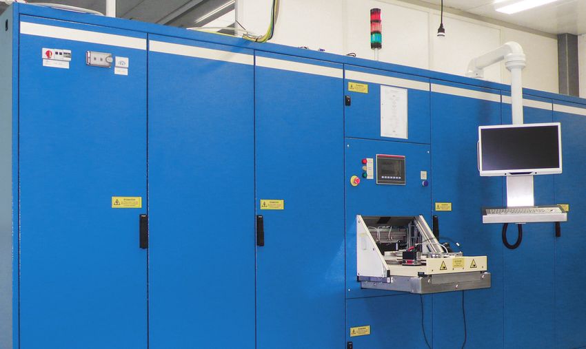
040 – 041 Test systems
042 – 043 Further documentation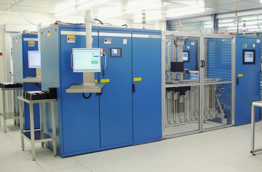
2
4         B
          PRRO
             OCDH
                UUCRTEBTRI O
                           T LCEHB
                                 URROECPHOUW
                                           REERS U
                                                 SEBM
                                                    T II T
                                                         CLOEN D U C TO R S

    2

           HVDC                              MARINE PROPULSION                INDUSTRIAL
        HVDC                                      MARINE                       INDUSTRIAL
                                               PROPULSION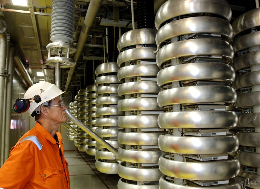
AR
                     A PT
                        P ILCI C
                               L AT
                                 E OI ORNCSH A P T E R T I T L E                                                            3
                                                                                                                            5

                                                                                                             3

RENEWABLES                     FACTS                               SHORE-TO-SHIP                     RAIL          E-MOBILITY
    R E N E WA B L E S                             FAC T S                         S H O R E -TO - S H I P       RAIL
6                    P R O D U C T B R O C H U R E P O W E R S E M I C O N D U C TO R S

RoadPak SiC e-mobility module
RoadPak is the first module for e-mobility applications in our proven portfolio of
power semiconductors that takes full advantage of silicon carbide (SiC) technology.

The RoadPak modules feature an innovative housing to comply with automotive
and e-mobility requirements.

Typical applications include:
• xEv Drive Train
• E-Bus
• E-Truck
• Charging stations
• Aux. Converters in Railway
• Marine
• Aviation

Power map

    1200 V

    750 V
                                                                                            Inom (A)
             200           400                600                800               1000   1200

RoadPak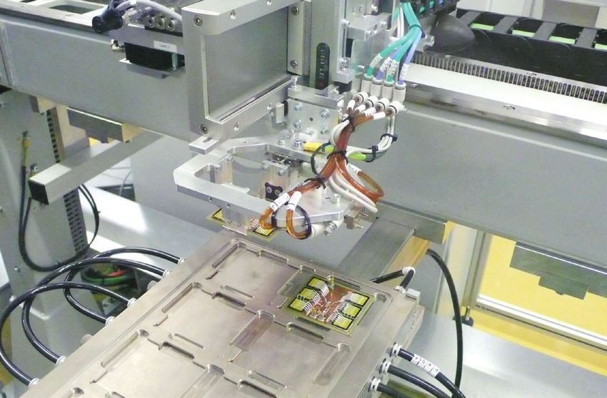
R OA D PA K                                                                                                    7

1. RoadPak                                                      Features                          Customer value
                                                                SiC chipset                       Highest switching frequencies
                                                                                                  with lowest losses, lowest size
                                                                                                  and highest current density
                                                                Sintered die-attach               Best thermal as well as best power
                                                                Copper bond wires                 cycling behaviour

                                                                Pin-Fin structure                 Best cooling performance while
                                                                                                  using cooling liquids
                                                                Ultrasonic welded main and aux.   Robust and reliable connections
                                                                contacts
                                                                High temperature encapsulation    Protection against humidity
                                                                molding

Thanks to its exceptional low stray inductance (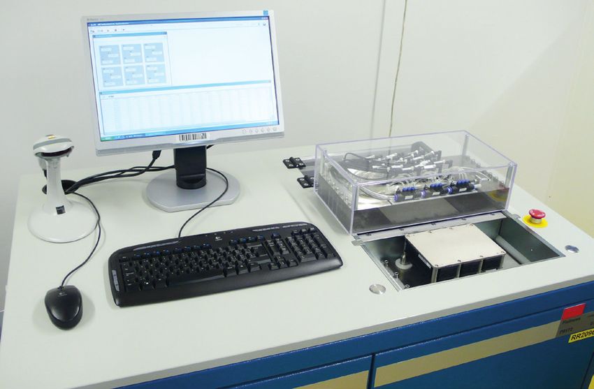
8                      P R O D U C T B R O C H U R E P O W E R S E M I C O N D U C TO R S

IGBT and diode chips
Hitachi ABB Power Grids' range of SPT+ and SPT++ (soft punch through) and TFP
(Trench Fine Pattern) IGBT and diode chips is available at 1200 and 1700 V, ranging
from 50 to 300 A.

Applications include power converters for industrial drives, solar energy, battery backup
systems (UPS), electrical vehicles, wind turbines and traction converters.

Power map

                                                                                            SPT++/FSA diode
                                                                                            SPT++ IGBT
    1700 V
                                                                                                                SPT+ diode
                                                    SPT+ IGBT

                                                                                                                TFP/ FSA Diode
    1200 V
                                                                       SPT+ diode
                                                                       SPT+ IGBT                                     Inom (A)
                  0           50                100                150                200      250            300            350

IGBT and diode chips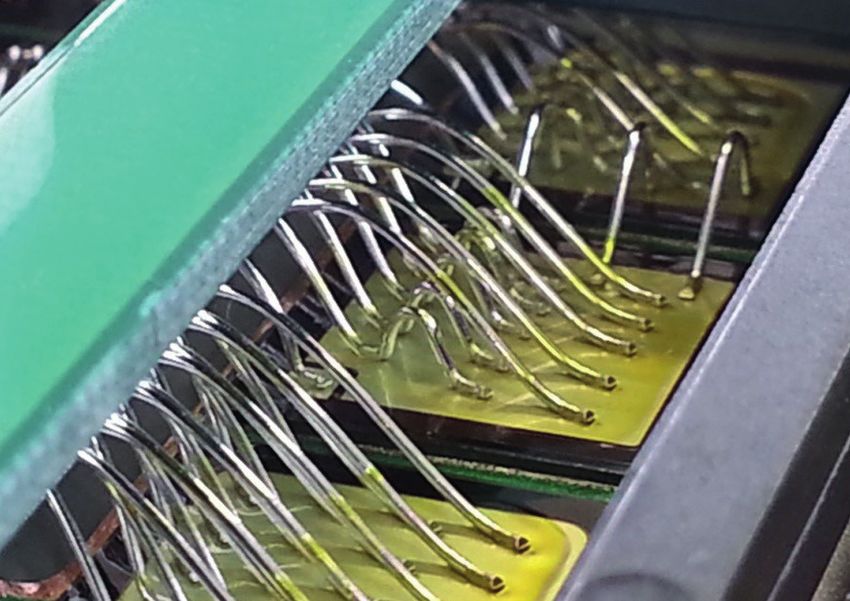
IGBT AND DIODE CHIPS                                                                                                                                                        9

                                                                  The Planar IGBT
2. IGBT and diode chips                                           IGBTs using the advanced SPT+ technology benefit from a
                                                                  conduction loss reduction of 20 to 30 percent compared to
                                                                  earlier SPT technology.

                                                                  Figure 1 shows the basic difference between SPT+ and SPT++.
                                                                  The on-state losses are reduced by introducing an
                                                                  N-enhancement layer surrounding the channel-P-well. This
                                                                  improves the plasma concentration on the emitter side and
                                                                  therefore, lowers the on-state losses. With the introduction
                                                                  of the SPT++, the profile of the said N-enhancement layer was
                                                                  further optimized with the main goal to make another step in
                                                                  conduction loss improvement. Together with thinner silicon,
                                                                  a reduction in VCE SAT of half a volt was possible.

                                                                                                                                       p+ well                        p+ anode

                                                                                                                                                                                  Collector log dop conc
                                                                                                                Emitter log dop conc
                                                                                                                                                     Plasma conc.

Hitachi ABB Power Grids' IGBT and diode chips with soft                                                                                          n+ layer

punch through (SPT) planar technology, feature the highest                                                                                                   n-       n+ buffer

switching performance, ruggedness and reliability.
                                                                                                                                       p+ well                        p+ anode

                                                                                                                                                                                  Collector log dop conc
Hitachi ABB Power Grids offers the most complete product
                                                                                                                Emitter log dop conc

                                                                                                                                                            E-field
portfolio of any supplier of high power semiconductors.
                                                                                                                                                 n+ layer

Its power semiconductor BiMOS chipsets, comprising IGBTs                                                                                                     n-
                                                                                                                                                                      n+ buffer
and free-wheeling diodes, offer the best switching performance,
ruggedness and reliability. Through moderate chip shrinkage
                                                                  Fig. 1 SPT+ planar IGBT enhanced carrier profile
and thus larger die area, Hitachi ABB Power Grids provides the
highest output power per rated ampere in the industry.

The new 1700 V SPT++ chipset is the world’s first to offer an     The Trench IGBT
operational junction temperature of up to 175 °C, enabling a      Starting 2021 we will also offer IGBT chips based on a Trench
significant increase in the power density of power modules.       Fine Pattern (TFP) technology. They build on the
                                                                  N-enhancement technology that we mastered with the SPT++
The breadth of different current ratings and sizes supports       chips and add a very compact fine patterned trench cell to
the various requirements in package design and output power.      further improve the conduction and switching losses by more
All chipsets are for solder mount-down and wire bonding in        than 30 percent compared to the SPT++ technology.
modules.
10                             P R O D U C T B R O C H U R E P O W E R S E M I C O N D U C TO R S

Figure 2 shows the on-state curves of the newest SPT++ IGBT
chip with 150 A rating at different temperatures. The SPT+ IGBT
shows a positive temperature coefficient of VCE on,
already at low currents. This enables a good current sharing ca-
pability between the individual chips in the module.

                                                                                         Fig. 3 IGBT turn-off of a SPT++ 150 A 1700 V IGBT

                                                                                         The diode
                                                                                         The diode of the new SPT++ chipset is based on an advanced
                                                                                         pin-diode design using the FSA (field-shielded anode).
                                                                                         A schematic cross-section is shown in figure 4. In contrast
                                                                                         to more conventional design, the FSA diode has a double
                                                                                         anode with a deep diffused P-well that shields the field from the
                                                                                         anode and the irradiation. Thus a significant leakage
                                                                                         reduction can be achieved without sacrificing the excellent ro-
                                                                                         bustness and low losses of the diodes.

                                                                                                           Conventional                                 FSA concept

                                                                                                p+               E-field
                                                                                                                                 Cathode

                                                                                                                                                                           Cathode
                                                                                        Anode

                                                                                                                                           Anode

Fig. 2 On-state curves of the 150 A 1700 V SPT++ IGBT
                                                                                                Deep                                               p+
                                                                                                levels                      n+                                        n+

                                                                                                            n-                                          n-

                                                                                         Fig. 4 Schematic cross-section of the diode
Figure 3 shows the turn-off of a 150 A 1700 V SPT++ IGBT
under nominal conditions at 175 °C. The IGBT exhibits
controlled switching characteristics as well as short current
tails. This behavior is enabled by the combination of SPT buffer
design and silicon resistivity used in SPT++ techno-
logy, which provides fast switching with low losses and low
overshoot.
IGBT AND DIODE CHIPS 11
The typical forward characteristics are shown in figure 5. Reliability
Figure 6 shows the reverse recovery characteristics of a Chipset reliability is confirmed using a combination of
150 A 1700 V diode under nominal conditions at 150 °C. standard tests. These include HTRB (high temperature
The current transients during switching are very smooth reverse bias), HTGB (high temperature gate bias), THB
and soft. (temperature humidity bias), cosmic ray test and a newly
developed test, which combines high temperature, high
humidity and high voltage.
To extend chipset reliability for extreme environmental
applications, the designs feature a state-of-the-art double-
layer passivation of silicon nitride and polyimide. The
polyimide layer mechanically protects the first passivation layer.
As such it acts, on the termination, as a delay-barrier against
outside humidity and ion-penetration. It further prevents
sparking across the termination during high-voltage operation.
Fig. 5 VF curve of a 150 A 1700 V FSA diode
Fig. 6 Reverse recovery of a 1700 V 150 A diode12 P R O D U C T B R O C H U R E P O W E R S E M I C O N D U C TO R S
Medium-power IGBT modules
Hitachi ABB Power Grids enhances its successful IGBT module range into the medium-
power segment. Starting with the 62Pak and the LoPak1, Hitachi ABB Power Grids brings
the proven high quality and reliability of the HiPak modules to the medium-power IGBT
segment.
The medium-power IGBT offering includes: Key benefits of medium-power IGBT modules include:
• 1200V LoPak1 dual/phase leg module, rated at 600, 900 A • Trench fine pattern TFP chipset for 1200 V
• 1700 V 62Pak phase leg modules, rated 150, 200 and 300 A • Ultra low-loss and rugged SPT++ chipset for 1700 V
• 1700 V LoPak1 dual/phase leg module, rated at 225, 300 • Smooth switching SPT++ chipset for good EMC
and 450 A • Cu baseplate for low thermal resistance
• Industry standard packages
The LoPak1 is 100 percent mechanically compatible with
EconoDual TM type modules.
Power map
1700 V
LoPak1
62Pak
1200 V LoPak1 Inom (A)
0 100 200 300 400 500 600 700 800 900 1000
Medium-power IGBT modulesMEDIUM-POWER IGBT MODULES 13
Typical applications include:
3. 62Pak IGBT modules • Variable speed drives
• Power supplies
• Power quality
• UPS
• Renewable energies
Features Customer value
Spacers for substrate solder, Longer lifetime under cyclic loads
homogeneous solder thickness (e.g. thermal cycles).
and less delamination.
Pre-bowed and stamped baseplate, Higher thermal utilization
reduced gap and lower interface more power and longer lifetime.
resistance.
Spacers for main terminal solder, Longer lifetime under cyclic load
homogeneous and thus stronger and more robust against vibrations.
solder layer.
The 62Pak modules feature an industry standard
housing, very low losses and highest operating
temperatures.
4. LoPak1 IGBT modules Typical applications include:
• Wind power converters
• Variable speed drives
• Power supplies
• Power quality
• UPS
• Renewable energies
Features Customer value
Special treated Cu-baseplate, Higher thermal utilization,
controlled bow and reduced airgap more power, longer lifetime.
to heat sink. This yields to a lower
thermal interface resistance and
significantly reduce grease pump-out.
Spacers for substrate solder, Longer lifetime under cyclic loads
homogeneous solder thickness (e.g. thermal cycles).
and less delamination.
The LoPak1 module is 100 percent mechanically Press-fit auxiliary connections, Simplified attachment of gate
compatible with the EconoDualTM type IGBT modules. press-fit auxiliary pins allow driver saves manufacturing costs.
a solder-free connection to the Higher reliability compared to
Hitachi ABB Power Grids' LoPak1 sets a benchmark
gate-driver PCB. Press-fit pins solder connection.
with full switching performance up to 175 °C. can also be soldered.
Copper wire bonds for high Lower connection,
It is specifically designed for excellent internal current current terminal and substrate resistance/losses
inter-connects.
sharing offering optimal thermal utilization and increased
robustness. Thus customers can expect larger safety Note: EconoDUAL™ is a registered trademark of Infineon Technologies AG, Germany.
margin and increased lifetime.14 P R O D U C T B R O C H U R E P O W E R S E M I C O N D U C TO R S
k TIM – Thermal Interface Material The amount of thermal material applied and its
application pattern, however, significantly impact
LoPakGridsTIM –offers
Thermal Interface Material the thermal resistance of the interface.
appliedThe TIM
hi ABB Power LoPak 1700 V with an The amount of thermal material and its Im
comes in a paste
application formhowever,
pattern, and is applied using
significantly impact Th
nal feature: the pre-applied Thermal Interface
automatic stencil
the thermal printing ofduring
resistance moduleThe TIM
the interface. he
ial (TIM).Hitachi
The TIM
LoPak use
ABB – of TIM Grids
Power
Thermal improves
Interfaceoffers the
LoPak
Material thermal
1700 V with an The comes
amount of
optional fabrication. It thermal
in a pastematerial
remains solid
form applied
and and its application
atisroom
applied temperature,
using po
Hitachi ABB Power Grids offers LoPak 1200 and Interface
uction at the modulefeature: the pre-applied
baseplate/heat Thermal
sink interface
1700 V with pattern, however,
automatic significantly
stencil printing impact the thermal
during module resistance de
reducing the potential for damage to the print
ing moreMaterial
anstability
optional(TIM).
overThe
feature: theuse
long-term of TIM
pre-applied improves
operation.
Thermal the thermal
Interface Material of the interface. The TIM comes in a paste
fabrication. It remains solid at room temperature, form and is applied the
conduction atofthe
TIMmodule baseplate/heat sink interface pattern by accidental contact and making module
e 1 below(TIM).
showsThe usethat heat improves
generatedthe thermal conduction
by power at the using automatic stencil printing during module
reducing the potential for damage to the print fabrication. 9,4
ensuring more stability over long-term
module baseplate/heat sink interface ensuring more stabilityoperation. handling and installation easier for the customer.
s during the
Figureoperation
1 below of IGBT
shows thatswitches
heat generated must by bepower pattern by accidental contact and making module sp
over long-term operation. The pattern
It remains design
solid
handling at roomof
and the TIM
temperature,
installation easier takes
reducing
for theinto account
the potential
customer. for
jun
ported from theduring
losses chip, the throughoperationthe ofmodule,
IGBT switchesto the must be damage to the print pattern by accidental contact and making
the locations
The pattern of design
highestofheat the TIM generation
takes into and the
account cy
sink to prevent
Figure 1 the
transported
below junction
from
shows thethattemperatures
chip,
heatthrough
generated the byof the losses
module,
power to the module handling and installation easier for the customer.
heat sink to prevent the junction intentional baseplate
the locations bending
of highest heat of the
generation module,
and the re
from rising beyond
during maximum
the operation of IGBT switchestemperatures
allowable mustlimits. Theof thefrom
be transported
intentional baseplate bending ofmetal-to-metal
the module, •A
ace betweenchips from rising
thethrough
the chip, module beyond
baseplate
the module, maximum
to the and allowableprevent the Thewhile
thetoheat
heat sink limits. ensuring
The pattern design the best
of the TIMpossible
takes into account the locations
while ensuring the best possible metal-to-metal the
interface between the module baseplate and the heat contact is heat made between theintentional
module baseplate
an have junction temperatures
the highest thermal of the chips from
resistance rising beyond
of all of maximum of highest generation and the
contact is made between the module baseplate
baseplate
the
sink can have the highest thermal resistance
allowable limits. The interface between the module baseplate of all of and the
bending heat
of the sink.
module, while ensuring the best possible
terfaces the
in that path, asthat
and interfaces
the heat sinkincan
seen path,
have
inhighest
the as
the chart
seen below
in the
thermal chart below
resistance of all
and the heat sink.
metal-to-metal contact is made between the module baseplate
us
1. •A
figure 1.
of the interfaces in that path, as seen in the chart below figure 1. Comparison and the heatof sink.
thermal materials
Comparison of thermal materials the
Appearance
Appearance Paste
Paste TIM
TIM wh
Comparison of thermal materials co
Color white or grey grey
Color white or grey grey
Appearance Paste phase change
TIM
Base material silicone fluid with filler phase change
Base material silicone fluid with filler material with filler The
Color white or grey grey
material with filler ave
Consistancy @ room
Base material silicone viscous
fluid with filler phasehard
change 940
Consistancy @ room
temperature
viscous material
hardwith filler
Thermal conductivity
temperature Jun
Consistancy @ room viscous0.8 – 3.0 hard 5.2
Thermal(W/(m*K)
conductivity
temperature 0.8 – 3.0 5.2
(W/(m*K) Cas
Thermal conductivity 0.8 – 3.0 5.2
(W/(m*K)
Pe
Figure 1 – Heat flow pathway through module and layer contributions
Fig. 1 Heat flow pathway through module and layer contributions
Th
he
Heat flow pathway through module
Layer and layer contributions
Contribution to thermal resistance at
Baseplate to terminal material
50% res
(thermal paste)
Layer Contribution to thermal resistance
Layer Contribution to thermal resistance (w
Device
Baseplate to terminal material 3% 50%
e to terminal material
(thermal
pa
Solder paste) 50% 6%
paste) he
Device
Base substrate - ceramic 33% 3%
3% of
Solder
Base substrate - DBC 3% 6%
6%
co
Base substrate - ceramic
Base plate 5% 33%
sh
bstrate - ceramic
Base substrate
Contributions - DBC
to module 33%
thermal resistance 3%
cyc
bstrate - DBCBase plate 3% 5%
pa
Figure 2: Base plate bottom surface with applied TIM
te Contributions to module thermal5%
resistance du
Comparison of thermal materials
ons to module thermal resistance Fig. 2 Base plate bottom surface with applied TIM
Heat conducting paste is applied manually using
stencil printing,
Comparison leading
of thermal to high variability in the
materials
Figure 2: Base plate bottom surface with applied TIM
amount of material applied
Heat conducting paste is applied and non-uniformity
manually of its
using stencil
parison of thermal
printing, leadingmaterials
application across the interface area. The paste also
to high variability in the amount of material
remains
applied
conducting viscous
and is
paste after
non-uniformityapplication.
of its application
applied manually usingacross the inter-
l printing,face area. The paste also remains viscous after application.
leading to high variability in the
nt of material applied and non-uniformity of its
ation across the interface area. The paste also
ns viscous after application.MEDIUM-POWER IGBT MODULES 15
Improved performance using TIM
formance The better using TIMof TIM compared to heat conductive
thermal stability
mal stability of TIM compared to
pastes can be seen during power cycling, a standard test to
simulate the degradation of the module over its lifetime by
e pastes can be seen
thermo-mechanical stress. The during
test was run for 9,400 cycles, in
line with the JESD51-14 specification, using the maximum al-
a standard testtemperature
lowable junction to simulate of 150 °C, the
with a total cycle time
the module over its lifetime by
of 120 seconds (t = t = 60 s).
on off
nical stress.
The results of The testshowed:
this testing was run for
n line with the JESD51-14
• A 7 percent improvement in the average thermal resistance
for the entire pathway from the IGBT junctions to ambient
using thewhen maximum allowable
the TIM is used instead of heat conductive pastes
• An 11 percent improvement in the average thermal resistance Fig. 3 Comparison of TIM and heat conductive paste stability
rature of from150the case°C, withwhen
to ambient a total
the TIM is used instead of
20 seconds (ton = toff = 60 s). The
heat conductive pastes Figure 3: Comparison of TIM and heat conduc-tive paste
stability
esting Thermal
showed: resistance,
mprovement
average over
in the Paste
9400 cycles (K/kW) average TIM Improvement
nce forJunction
theto ambient
entire pathway
Case to ambient
114.75
73.92
from 11%
106.66
65.93
7%
ions toPerformance
ambient whento heat
of TIM compared the TIMpasteis
conductive
f heat conductive pastes
t improvement in the average
The impact of using the TIM rather than the heat conductive
nce from
paste canthebe case to ambient
seen by looking at data from the test for the partial
s usedTIMinstead of heat
thermal resistance from the case to the heat sink (where the
is located) and for the entire path between the transistor
stes junction and the heat sink. While the initial thermal conductivity
of pre-applied TIM is comparable with the heat conductive
paste, the modules using TIM show no increase in thermal
resistance with cycling, while those using the heat conductive
paste show increasing thermal resistance during the test.
Paste TIM Improvement
114.75 106.66 7%
73.92 65.93 11%
ared to heat conductive paste
using the TIM rather than the
e paste can be seen by looking
e test for the partial thermal
m the case to the heat sink
is located) and for the entire16 P R O D U C T B R O C H U R E P O W E R S E M I C O N D U C TO R S
High-power IGBT modules
Three high-power IGBT and diode module families - LinPak, HiPak and StakPak –
are available in single and dual chopper and phase leg configurations, from
1700 to 6500 V and 150 to 3600 A.
The LinPak is an enabler for more reliable, efficient and compact HiPak type modules are the perfect match for demanding
inverter designs in traction applications such as used in regional high-power applications such traction, renewable energy
trains and metros, as well as locomotives and high-speed trains. (wind, solar), industrial drives and T&D.
LinPak also serves markets such as OHV (off-highway-vehicle)
and industrial converters for drives and wind power. Moreover, StakPak modules are suited for multiple-device stacks found
SiC LinPaks are offered as demonstrators for the highest in high-voltage DC transmission (HVDC) or FACTS applications.
required power and operational frequency.
Power map
HiPak single IGBT
6500 V
HiPak dual diode
5200 V StakPak BIGT
StakPak single
HiPak single IGBT
4500 V HiPak chopper
HiPak dual diode
HiPak phase-leg diode
HiPak phase-leg IGBT
HiPak single IGBT
HiPak chopper
HiPak dual diode
3300 V HiPak dual IGBT
SiC LinPak
LinPak phase-leg IGBT
LinPak phase-leg diode
LinPak phase-leg IGBT
HiPak single diode
HiPak single IGBT
HiPak dual
1700 V
HiPak chopper
SiC LinPak
LinPak phase-leg Inom (A)
0 500 1000 1500 2000 2500 3000 3500 4000
HiPak, StakPak and LinPakHIGH-POWER IGBT MODULES 17
LinPak is suitable for more reliable, efficient and compact
5. LinPak IGBT modules inverters for use in regional trains and metros and locomotives
and high-speed trains. It also serves markets such as OHV
(off-highway-vehicle) and industrial converters for drives and
wind power.
Developments
We have has developed highly reliable traction rated modules
including:
• 1700 V / 2 x 1000 A
• 3300 V / 2 x 450 A
• Cu-based industrial versions at 1700 V and later 1200 V
are targeted
High-voltage versions ranging from 3300 V up to 6500 V with
the same footprint, but rearranged electrical connections to
cope with the higher clearance and creepage requirements,
are in development.
LinPak is a new open standard, phase leg IGBT module,
LinPaks Voltage (V) Current (A)
rated 1700 and 3300 V, offering exceptionally low stray
AlSiC / (Cu*) 1700 2 x 1000
inductance. Its separated phase- and DC-connections
AlSiC 3300 2 x 450
allows for simpler inverter designs.
*
Copper version in consideration
Features
The very low-inductive internal module design and the massive Exemplary nominal switching waveforms
DC-connection enables a very low-inductive busbar design The exemplary switching waveforms at nominal current show
with a high current carrying capability. Both are essential the benefit of the low overall stray inductance. Despite the fast
requirements for state-of-the-art silicon chipsets and future switching and the very low switching losses of the 1700 V SPT++
SiC solutions. IGBT chipset, the overvoltage remains at a very low level.
The current and voltage waveforms are free of oscillations. In
LinPak modules feature excellent internal and external current the present setup, a total stray inductance including capacitors,
sharing, making them especially suitable for paralleling. Thus busbar and module of less than 25 nH per 1000 A phase leg
with just one module type a large range of inverter ratings is has been attained.
possible. LinPak features an integrated temperature sensor
and a dedicated mounting area for a gate drive adapter board. Using the very low stray inductance of the LinPak modules
For harsh environments in traction or off-highway vehicle and the commutation circuit, the use of a novel semiconductor
applications, the adapter board can be additionally fixed with material, the Wide Band Gap (i.e. SiC) is now possible.
four screws in the module corners. We are offering demonstrators rated at 1700 V and 3300 V,
in the range of 500 A up to 1800 A.
The LinPak offers a fast and low switching loss 1700 V SPT++
and 3300 V SPT+ chipset that ideally fits to the LinPak module.
LinPak is the first up to 3300 V rated module with an integrated
temperature sensor and offers unrivalled reliability thanks to
well-matched materials such as aluminum nitride (AlN) insulation
and aluminum silicon carbide (AlSiC) baseplate, as well as
advanced wire bonding techniques and particle free ultrasonic
welded main connections.18 P R O D U C T B R O C H U R E P O W E R S E M I C O N D U C TO R S
Parallel connection
As there is practically no current mismatch between paralleled
modules, LinPak is ideal for parallel connection. See the
exemplary turn-on switching curve of four paralleled modules:
1700 V LinPak turn-on switching curves
1700 V LinPak turn-off switching curvesHIGH-POWER IGBT MODULES 19
SPT+ technology
6. HiPak IGBT modules SPT+ retains all the features of the SPT technology but
reduces VCE SAT by up to 30 percent according to the curve
in figure 1 – an achievement previously possible only with
trench technology.
HiPak high-power IGBT modules come in industry
standard housings measuring 190 x 140 mm, 130 x 140 mm
and 140 x 70 mm. The modules are suitable for demanding
high-power applications such as traction, transmission &
distribution, renewable energy (wind, solar) and industrial Fig. 1 Vce sat for different IGBT cell technologies on SPT silicon at 125 °C.
(current density of SPT range, same Eoff )
drives.
HiPak modules are available in 4, 6 and 10.2 kVRMS standard
isolation voltages and a variety of circuit configurations.
TSPT+ technology
The modules exclusively use AlSiC baseplate material and AlN The enhanced Trench cell technology combines the merits of
isolation with low thermal resistance. This specific material the SPT+ with its n-enhancement layer and the latest Trench-cell
combination offers an excellent power cycling performance due technology. Figure 2 shows a cross-section through the cell.
to its matched thermal expansion coefficients (CTE).
E
MOS cell G
All HiPak modules feature advanced SPT and SPT (soft punch
+
through) chip technology. The technology combines low losses
with soft switching performance and a record breaking safe
operating area (SOA). N-enhancement layer
HiPak SPT chips are optimized for reliable operation under Trench-gate
harsh conditions through smooth switching characteristics and
rugged operation (high SOA) which translates into operational
safety margins for the equipment. Furthermore, the SPT+ chip-
sets (IGBT and diode) at 1700 V and 3300 V blocking voltages
are improved to operate at higher junction temperatures up to SPT buffer
150 °C within the HiPak modules.
SPT technology C
SPT is a well-established planar IGBT technology extending
Fig. 2 TSPT Enhanced Trench cell design
+
from 1200 V to 6500 V. It is characterized by smooth switching
waveforms and exceptional robustness which is of importance
at higher voltages and currents, where stray inductances are
not easily minimized.20 P R O D U C T B R O C H U R E P O W E R S E M I C O N D U C TO R S
This shows reduced conduction losses and a further increase The 6500 V and 4500 V SPT++ IGBTs serve as an easy upgrade
of the current density of up to 20 percent compared to previous for existing converter designs, either to increase power or to
designs. First employed in the 3300 V class, Hitachi ABB Power reduce the inverter size.
Grids offers a HiPak module with 1800 A nominal current.
Increased reliability with improved HiPak
The Hitachi ABB Power Grids Trench cell offers highest The improved HiPak modules are a direct one-for-one
ruggedness, avoiding unwanted degradation effects in the replacement with identical electrical and thermal characteristics.
usual operating area that are often attributed to high voltage The principal electro-mechanical layout remains unchanged.
Trench cell designs. The improvements are realized by the following features:
The enhanced Trench TSPT+ technology offers superior Housing construction
turn-off capability with large margins to the normal operation For low-voltage (LV) HiPak modules the epoxy casting is
area. Figure 3 shows the turn-off SOA of the 3300 V TSPT+ removed, allowing case temperature rating to increase to
with more than 3x nominal current: TC max = 150 °C. The new package complies with the latest
fire and smoke requirements for traction applications.
This applies to the low- and high-voltage versions:
• NFF 16-101/102 I3 – F2,
• EN 45545-2 R23: >HL1, R24: >HL2
Internal auxiliary connection
Internal solder connections between the gate-print and the
substrate will be substituted by standard aluminum wire
bonding. This well-established technology allows for higher
reliability and offers a redundant double wire connection
(figure 4).
Fig. 3 3300 V TSPT+ HiPak2 IGBT module with >3x nominal current turn-off at 150 °C
SPT++ technology for 6500 V and 4500 V
For the highest 6500 V, Hitachi ABB Power Grids has further
improved the enhanced planar design, resulting in exceptionally
low switching losses and increased current density by up to
30 percent: achieving a 1000 A at 6500 V and 1500 A at 4500 V
rated IGBT modules. Like their predecessors, the 6500 V
and 4500 V SPT++ designs offer unrivalled robustness with
minimum design-in risks.
Proof of this capability is represented by the full 150 °C
operation temperature capability with a large safe operating
area (SOA). Figure 4 shows the turn-off SOA of the 6500 V
SPT++ IGBT with 2.5x nominal current at 150 °C.
Fig. 4 New redundant aluminum wire bond connection of gate and auxiliary emitter
Terminal foot
The main terminals offer an improved solder foot with
specifically designed spacers that achieve a homogenous sol-
der layer thickness. This allows for an improved
temperature cycling performance.
Fig. 4 6500 V SPT++ HiPak2 IGBT module with 2.5x nominal current turn-off at 150 °CHIGH-POWER IGBT MODULES 21
Wire bonding The new design is subjected to relevant testing including shock
The emitter side wire bonding parameters are improved and vibration, temperature cycling, IOL and
and stich-bonds (figure 5) being used. This results in an Temperature Humidity Biased (THB).
improvement of factor 4 in intermittent operating life (IOL) (tar-
get 2 Mcycles T = 60 K, Tvj max = 150 °C).
Fig. 5 Stich-bond layout and improved bonding parameters boost the power
cycling capability
Smart power semiconductors They capture the temperature and humidity within the IGBT
The conditions under which power modules operate can deviate module, storing the data locally. This data can be transmitted
significantly from those assumed in the data sheet or product to the data logger via Bluetooth, allowing it to be remotely
specifications. Condition monitoring techniques, predominantly accessed and visualized in real-time, or downloaded for further
to monitor the junction temperature, Tj have therefore been analysis.
developed to ensure reliability. Please contact us for more information about the benefits of
this technology.
More recently there has been a focus on the effects of humidity
on semiconductor and converter reliability, particularly in LinPak
applications such as rail traction systems, to address the risk
of condensation triggering corrosion of metallic conductors,
electrochemical migration, degradation of junction passivation
and conductive anodic filament formation on PCBs. Many
modern modules for the traction industry are now equipped with
humidity sensing to detect potentially harmful condensation
events occurring during operation. Figure 3 shows the Hitachi
ABB Power Grids LinPak and HiPak modules equipped
with a conditionmonitoring platform that includes humidity
HiPak
and temperature sensing, on-board memory and wireless
communication.
The condition monitoring platform is divided into two parts:
the measurement electronics (integrated into an IGBT module)
and a data logger built into a converter for long-term data
storage. The measurement electronics are powered by the
gate drive.
Figure 1: Hitachi ABB Power Grids LinPak and HiPak modules equipped with a condition-
monitoring platform that includes humidity and temperature sensing, on-board memory
and wireless communication.22 P R O D U C T B R O C H U R E P O W E R S E M I C O N D U C TO R S
—
6. StakPak press-pack IGBT and
BIGT modules
BIGT StakPak
7. StakPak press-pack IGBT BIGT StakPak
Additionally to the
Additionally to standard
the standardIGBT/IGBT/
Diode Diode
choice,choice,
Hitachi ABB
and BIGT modules Power Grids
Hitachi ABBis also
Power offering
GridsStakPaks with Bi-mode
is also offering Insulated
StakPaks
Gate
withTransistor
Bi-mode(BIGT). Besides
Insulated Gate offering a state(BIGT).
Transistor of the art
Besides
current offering
density, a state
the BIGT of the art
is improving currentby
reliability density,
reducing
the BIGT is improving reliability by reducing
the temperature ripples and massively increases diode the surge
temperature
current capability.ripples and massively increases diode
surge current capability
StakPak high-power IGBT and BIGT press-pack modules Fig2. the BIGT concept
Fig. 2 the BIGT concept
feature advanced modular housing that ensures uniform
chip pressure in multiple-device stacks. StakPak product range
StakPak high-power IGBT and BIGT press-pack modules StakPakmodules,
StakPak product range
unlike standard IGBT modules, fail into a
Forfeature advanced
applications modular
requiring housing
series that ensures
connection, uniform
press-pack StakPak
stable modules, unlike
short-circuit failurestandard IGBT modules,
mode (SCFM). fail into a
SCFM capable
chip pressure
modules in multiple-device
are preferred. stacks.
Press-pack are easy to connect stable short-circuit
StakPaks failure
are suitable mode (SCFM).
for applications SCFM
with capable
series connec-
electrically and mechanically in series and have an inherent StakPaks
tions withare suitable forInapplications
redundancy. with series
such applications, connections
additional
For applications
ability to conduct in requiring seriesstate
the shorted connection, press-pack
– an essential feature with redundancy.
devices In such
are inserted in theapplications, additional
series string so that adevices
device’sare
modules
where are preferred.
redundancy Press-pack are easy to connect
is required. insertedwill
failure in the
notseries string
interrupt so that aoperation.
converter device’s failure will not
electrically and mechanically in series and have an inherent interrupt converter operation.
ability
Since IGBTto modules
conduct in the shorted
feature state
multiple – an essential
parallel feature
chips, there is a The failed device continues to conduct current for a period
where redundancy
challenge is required.
– with conventional press-packs – in assuring The failed
greater device
than continues to conduct
the equipment’s planned current
service for a period
interval. This
uniform pressure on all chips. This problem was solved with greater during
period, than thewhich
equipment’s planned
load current mustservice interval.
flow in This
the failed
anSince IGBT modules
advantageous feature
spring multiple parallel chips, there is a
technology. device during which
period,without loaddegradation
external current mustofflow
thein the failed
housing or
challenge – with conventional press-packs – in assuring device without
internal external
degradation ofdegradation ofcontact,
the electrical the housing
is a or internalof
function
uniform
The pressure
StakPak, on allfor
optimized chips. Thisconnection,
series problem was solved with
features a degradation
the of the
load current electrical contact, is a function of the load
time-dependence.
an advantageous
modular spring
concept based ontechnology.
sub-modules fitted in a current time-dependence.
fiberglass reinforced frame (figure 1). Thus a range of Hitachi ABB Power Grids offers SCFM ratings for users
The StakPak,
products can beoptimized
developed forfor
series connection,
different currentfeatures
ratings aand Hitachi ABB
requiring thisPower Grids
feature andoffers SCFM
who are ratings
able for users
to specify the load
modular
IGBT concept
/ diode ratios.based on sub-modules fitted in a fiberglass requiringwaveforms
current this featureand
andprofiles.
who areFor
ableapplications
to specify the
notload
reinforced frame (figure 1). Thus a range of products can be current waveforms
requiring and profiles.
a stable short For applications
over a longer not requiring
period, Hitachi ABB
developed for different current ratings and IGBT / diode ratios. a stableGrids
Power shortcan
overprovide
a longer period, Hitachi
non-SCFM ratedABB Power Grids
modules.
can provide non-SCFM rated modules.
Furthermore, although a non-SCFM rated StakPak module
Furthermore,
fails although
into a short, a non-SCFM
a stable short canrated
only StakPak module
be guaranteed
failstointo
up oneaminute.
short, a This
stableis short can only be
still sufficient guaranteed
time to engageup
anto
one minute.
external This or
bypass is take
still sufficient time to engage an external
other measures.
bypass or take other measures.
Press-pack technologies
Press-pack
Two technologies
basic multi-chip press-pack technologies exist: chips
Two basic multi-chip
contacted by commonpress-pack technologies
pole-pieces exist: chips
(figure 3: conventional
— contacted byand
technology) common
chipspole-pieces
contacted by(figure 3: conventional
individual springs
Fig. 1 Submodules in a 6-pocket StakPak module technology)
(figure and chips
4: StakPak contacted by individual springs
technology).
(figure 4: StakPak technology).
Fig. 1 Submodules in a 6-pocket StakPak moduleHIGH-POWER IGBT MODULES 23
molybdenum inert gas
ceramic
copper
The rigidity and stability of a stack subjected to shock or vibra-
tion in service or during transportation depends on a mounting
Silicon
chip force that may not always coincide with that required by the
encapsulated chips. It is, therefore, important to decouple the
Close-up two forces, allowing the optimal force on the chips to be lower
copper
than the optimal force on the stack. The individual springs of
Hitachi ABB Power Grids' StakPak allow this.
Fig. 3 Sectional view of conventional multi-chip press-pack with common
pole-pieces: each chip bears the device force divided by the number of chips. Applications
Press-pack modules are favored in applications where devices
sub-module frame
are series-connected mechanically and/or electrically. An
module outer frame
module lid
(polymeric) (fibreglass reinforced example of a long stack requiring SCFM can be seen in the
polymer)
(copper) spring HVDC valve of figure 6. Other press-packs applications include:
current bypass washer
pack • HVDC & FACTS (Flexible AC Transmission Systems)
• Topologies in which open circuits are not possible
(e.g., current-source systems)
• Multi-level inverters with 6 or more devices mechanically
in series
• Frequency converters operated directly from the 15 or 25 kV
AC traction catenary
Δx • Pulse-power applications, such as thyratron replacement
silicon chip base-plate
silicon gel
Fig. 4 Sectional view of Hitachi ABB Power Grids multichip press-pack with individual
spring contacts: the chip bears the force determined by the spring; excess force is borne
by the housing walls. The drawing illustrates one multichip submodule in one press-pack
housing.
Clamping operation:
F2 > F1 F3 > F2
F1
springs
F = c.Δx Fig. 6 Standard IGBT valve for VSC, HVDC and STATCOM
Fig. 5 Principle of individual emitter pressure contacts. F is the force, c the spring Summary
constant and Δx the travel distance.
StakPak technology is a well proven IGBT press-pack concept
that reduces cost and enhances reliability in systems requiring
The individual spring contacts reduce the heat sink flatness several press-packs in one stack. StakPak’s modularity allows
tolerance and the pressure uniformity requirement within the the product range to be configured from several standard parts,
stack that would otherwise be needed. This reduces the stack’s enabling rapid response to market needs. The newly introduced
mechanical construction costs and greatly increases field 4500 V rated modules feature the state-of-the art SPT+ chipset
reliability. The spring acts as an «independent suspension», so for lowest system losses and highest ruggedness and reliability.
that only the correct force is applied to each chip. This allows
excess force to be transferred to the StakPak housing wall
(figure 5). The force needed for a long stack may indeed be far
higher than that tolerated by the silicon chips being contacted
via their sensitive surface microstructures.24 P R O D U C T B R O C H U R E P O W E R S E M I C O N D U C TO R S
BiPolar power modules
Hitachi ABB Power Grids’ diode and thyristor modules feature industry standard housings
and very low losses together with the highest operating temperatures. They provide the
ultimate in reliability whether efficiently driving industrial motors, smoothly accelerating fans
and pumps, or supply power to demanding applications.
Power map
2200 V
Inom (A)
200 300 400 500 600 700 800 900 1000
60PakMODUL 60 ABB
BIPOL AR POWER MODULES 25
Target ratings 60Pak
8. 60Pak modules Configurations
DD Dio / Dio 1 2 3
Voltage (V) Ampere (A)
MODUL
1800 60 ABB 620
22001 890
TT Thy / Thy 5000 ratings 60Pak
Target 650
1 2 3
8. 60Pak
After successfully launching IGBT medium power modules
modules,
6000 480
Hitachi ABB Power Grids is introducing a BiPolar power
Product
MODUL
1
qualified
60 ABB
module perfecting the art of ultimate reliability – the 60Pak. 44
Voltage (V) 50 (A)
Ampere Confi
4x PIN 2,8x0,8
1800 620 TT, D
MODUL 60 AB
The key benefits of the new 60Pak are highest performance, 22001 890 DD
1 2 3
14
DT Dio / Thy
outstanding reliability and increased overload capability. 4
5
7
6 Configurations
5000 650 DD
All highest quality Hitachi ABB Power Grids’ assets wrapped Target ratings 60Pak
52
8. 60Pak modules
6000
DD Dio / Dio480 1DD2
in a standard industrial housing. MODUL
1
60 ABB 44
Product qualified 50
4x PIN 2,8x0,8
10
4xØ6,5
MODUL 60 AB
Features low voltage diode & thyristor modules MODUL 60 ABB
VoltageTD (V) Thy / DioAmpere (A) 1 2 Configurations 3
14
124
• Precisious pressure contacts for high reliability 4
5
7
6 Configurations
1800 620 TT, DD, DT, TD
• Industry standard housing
52
After successfully launching IGBT medium power modules, DDTT Dio /Thy
Dio / Thy 1 2 1 2
2200 1
890 44
DD 3xM10 50 25
• Insulated baseplate by AIN ceramic Hitachi ABB Power Grids is introducing a BiPolar 4x PINpower
2,8x0,8
10
• UL recognized module perfecting the art5000 of ultimate reliability – the 650 60Pak. DD MODUL MODUL
60 ABB60 AB
• Voltage range 1.8 - 2.2 kV 4x PIN 2,8x0,8 4xØ6,5
14
6000 pc Pressure 480
contact DD
4 7 124
• Forward current up to 890 A The key benefits of the new1 Product 60Pak are highest performance,
5 6
48
60
36
28
After successfully launching IGBT qualified
medium power modules, TT Thy / Thy 1 2 1 2
52
14
DT Dio / Thy2
outstanding
Hitachireliability
ABB Power and increased
Grids overload
is introducing capability.
a BiPolar power
1 4 7
5
44 6
3xM10 50 25
Typical diode applications All highest quality Hitachi ABB Power Grids’ assets wrapped
52
module perfecting the art of ultimate reliability4x – the
PIN 60Pak.
2,8x0,8 MODUL 360 ABB
10
MODUL 60 ABB 4x PIN 2,8x0,8 44
MODUL 60 AB
Uncontrolled line frequency bridge inarm in medium
a standard voltage housing.
industrial 25 4xØ6,5
(DT) 4x PIN 2,8x0,8
10
drives, input rectifiers in AC/AC convertersTheand
keyDC power
14
benefits of the new 60Pak are highest performance,
Configurations 124
112 1 2
14
4 7
DT Dio / Thy
supply for applications such as industrial outstanding
Featuresandlow reliability
voltage
renewables. and increased
diode & thyristor overload
modules
5
capability.
6 4 7
150
48
60
36
28
DD Dio / Dio 1 2 3 1 2
5 6
TD Thy / Dio
14
52
All highest quality Hitachi ABB forPower
high Grids’ assets wrapped
52
2
• Precisious pressure contacts reliability 1 4
5
7
6 3xM10 MODUL 25 60 ABB
in a standard industrial housing. 44
Typical thyristor applications • Industry standard housing
52
3
10
4x PIN 2,8x0,8
10
AC motor soft starters and variable •speed
Insulated
drivesbaseplate
in by AIN ceramic
Features low voltage diode & thyristor modules 25
4x PIN 2,8x0,8 4xØ6,5
10
TD Thy / Dio 1 2
14
applications such as industrial and •renewables.
UL recognized
• Precisious pressure contacts for high reliability 4
5
7
6
124
112
48
60
36
28
• Voltage range 1.8 - 2.2 kV
14
• Industry standard housing pc Pressure 150
contact
52
4 7 2
byTTA ceramic Thy / Thy
1
After successfully
Portfoliolaunching
outlook IGBT medium power
• Forward modules,
current
• Insulated up to 890
baseplate AIN
5 6
3xM10 25
44
48
60
1036
28
4x PIN 2,8x0,8
52
Hitachi ABB Power Grids is introducing a BiPolar UL power
•lineuprecognized 3
The BiPolar thyristor and diode modules will be 1
• Voltage
Typical range 1.8 - 2.2 kV
–diode applications 25
14
module perfecting
expandedthe art to
rapidly of different
ultimate reliability
voltages the 60Pak.
and configurations pc Pressure contact
4x PIN 2,8x0,8
10
44
4 7
50
• Forward
Uncontrolled current
line up to 890
frequency A arm in medium
bridge voltage
5 6
112
48
60
36
28
in the coming years. 4x PIN 2,8x0,8
52
150 1 (DT)
48
60
36
drives, input rectifiers in AC/AC converters and DC power 14 28
14
The key benefits of the new 60Pak are highest performance,
Typical diode applications 1
4 7
54x 6PIN
2
2,8x0,8 (TT) 44
3610
supply for applications such DTas industrialDio
and renewables.
(TD) / Thy
48
60
28
outstanding reliability and increased overload capability.
Uncontrolled line frequency bridge arm
4 in7 medium voltage
52
2
5 6
drives, input rectifiers in AC/AC converters and DC power
(DT)
3 1
14
All highest quality Hitachi ABB Power Grids’Typical
assets wrapped
52
thyristor applications
4 7
25
10
supply for applications such as industrial and renewables.
5 6
48
60
36
28
in a standard industrial housing.
52
AC motor soft starters and variable speed drives in 112 1
10
150
applications
Typical such as industrial
thyristor and renewables.
applications
36 10
4xØ6,5
48
60
28
Features low voltage diode & thyristor modules AC motor soft starters and variable speed drives in 2
applications TD Thy / Dio 1
Portfolio
• Precisious pressure contacts for high reliability outlooksuch as industrial and renewables. 124
48
60
36
28
• Industry standard housing The BiPolar thyristor and diode modules lineup will be 1
Portfolio outlook 3xM10
expanded rapidly to different voltages and configurations 25
• Insulated baseplate by AIN ceramic The BiPolar thyristor and diode modules lineup will be
in the expanded
coming years. 2
• UL recognized rapidly to different voltages and configurations
48
60
36
in the coming years. 28
• Forward current up to 890 A 1
48
60
36
28
pc Pressure contact (TD) 1
48
60
36
28
(TD)
Typical diode applications 1 2
2
Uncontrolled line frequency bridge arm in medium voltage 3
drives, input rectifiers in AC/AC converters and DC power 25
supply for applications such as industrial and renewables. 112
150
Typical thyristor applications
AC motor soft starters and variable speed drives in
applications such as industrial and renewables.
Portfolio outlook
The BiPolar thyristor and diode modules lineup will be
expanded rapidly to different voltages and configurations
in the coming years.26 P R O D U C T B R O C H U R E P O W E R S E M I C O N D U C TO R S
Diode press-packs
Hitachi ABB Power Grids' range of press-pack diodes covers
• Fast recovery diodes from 4500 to 6000 V and 175 to 2620 A
(GTO free-wheeling, IGBT and IGCT diodes)
• Standard rectifier and avalanche diodes from 1700 to 8500 V and
662 to 7385 A
• Welding diodes for medium and high frequencies from 200 to 400 V
and 7110 to 13526 A.
Power maps
5500 V IGCT diodes
4500 V IGCT diodes
4500 V IGBT diodes
6000 V GTO free-wheeling diodes
4500 V GTO free-wheeling diodes Inom (A)
0 500 1000 1500 2000 2500 3000
Fast recovery diodesD I O D E P R E S S - PAC K S 27
8500 V Standard rectifier
6000 V Standard rectifier
5500 V Standard rectifier
Avalanche
5000 V
Standard rectifier
4000 V Standard rectifier
3800 V Avalanche
Avalanche
3200 V
Standard rectifier
2800 V Standard rectifier
2600 V Avalanche
2400 V Standard rectifier
2300 V Avalanche
Avalanche
2000 V
Standard rectifier
1700 V Avalanche
High-frequency welding
400 V
Medium-frequency welding
200 V Medium-frequency welding Inom (A)
0 2000 4000 6000 8000 10000 12000 14000 16000
Rectifier and welding diodes28 P R O D U C T B R O C H U R E P O W E R S E M I C O N D U C TO R S
9. Fast recovery diodes
Typical diode turn-off in IGCT circuit.
A wide range of fast recovery, low loss diodes such as Features
clamping and free-wheeling diodes in various configura- • Free-wheeling diodes
tions are available, to enable full performance of the • Clamp diodes
IGCTs, IGBTs and GTOs in demanding applications. • Snubbered types
• Unsnubbered types
Fast recovery diodes, though an integral part of inverter design, • Soft recovery
have seldom received the same attention as turn-off devices • High SOA
such as IGBTs, IGCTs or GTOs. As a result, clamp, neutral-point • Cosmic ray resistance capability
clamping (NPC) and free-wheeling diodes (FWDs) often limit
optimal equipment design. Benefits
• High operating temperature range up to 140 °C
Recognizing this and the growing trend to eliminate voltage • Optimized forward and reverse recovery characteristics
snubbers on semiconductors, Hitachi ABB Power Grids has • Excellent softness and enhanced SOA
developed a full range of fast diodes offering enhanced safe • Cosmic radiation withstand rating
operating areas (SOA) and controlled (soft) recovery at very • Press-pack devices
high di/dt and dv/dt levels. The growing demand for switching
capability (ratings) and not just recovery charge or losses Applications
(characteristics) imposes new constraints on diode design and Fast diodes of a given blocking voltage and silicon wafer
production test equipment to ensure cost-effective delivery diameter are designed using five basic variables: resistivity,
of robust and reliable components. In contrast to turn-off thickness, uniform lifetime control, profiled lifetime control and
devices, thyristors and diodes are traditionally tested for their emitter efficiency. Combining these variables allows diodes
characteristics only and classified accordingly. to meet the requirements of five different commutation modes
encountered in voltage source and current source inverters
New generations of high-performance fast diodes, as (VSIs and CSIs). These are defined in table 1. One of the basic
5SDF 20L4520 / 21 and 5SDF 28L4520 / 21, are now tested for principles influencing the nature of a commutation is the origin
their dynamic characteristics and ratings on production test of the di/dt. There are two types of commutation:
equipment that accurately reproduces the main commutation
modes required of today’s fast diodes.
The fast diodes 5SDF 20L4521 and 28L4521 are developed to
operate safely in power electronic circuits employing IGBT and
IEGT press-packs, where di/dts up to 5 kA/μs are especially
required.D I O D E P R E S S - PAC K S 29
1. inductive commutation 2. resistive commutationn
whereby the active switch is considered «perfect» whereby the active switch is considered as a time-dependent re-
(eg a thyristor) and an inductance determines di/dt. sistor (eg a transistor) and this controls di/dt.
Category Application Snubber type Commutation characteristics Required diode characteristics
l FWD and NPC diodes for GTOs RCD • inductive • uniform lifetime
and IGCTs in low frequency VSIs • unclamped • high cosmic ray resistance
• snubbered capability
• low dv/dt • low VFM
ll Snubber diode in RCD circuits R • inductive • profiled lifetime
• unclamped • soft recovery at low lF
• snubbered
lll • Snubber diodes in Undeland, none • resistive • profiled lifetime
Marquardt and McMurray VSIs • unclamped • soft recovery at low lF
• Clamp diodes • unsnubbered
lV • Commutation diodes in CSIs RC • inductive • profiled lifetime
• High frequency series-connected • unclamped • medium cosmic ray resistance
IGCTs • snubbered capability
V FWD and NPC diodes in none • inductive • profiled lifetime
snubberless high frequency VSIs • clamped • high cosmic ray withstand
• high dv/dt capability
• high SOA
• soft recovery at low lF
Cosmic ray resistance capability The snubber and clamp diodes, however, due to their infrequent
An important parameter for the rating of any semiconductor exposure to the DC link (duty cycle of approximately
in a converter is the voltage to which it is exposed. This 5 percent), would be better served with diodes of lower
has two reasons: the stability of the leakage current at rated DC rating (thinner silicon), thus endowing them with superior dy-
temperature and the potential failures provoked by ionizing namic properties (fast forward and reverse recovery, low losses,
cosmic particles – events whose probability of occurrence no snap-off). For further information see application note
increases exponentially with field strength but only linearly 5SYA2061 «Failure Rates of Fast Recovery Diodes due to Cos-
with voltage duty cycle. The various functions within power mic Rays».
conversion equipment may be exposed to different voltages
and duty cycles even though the peak voltages might be the
same. Thus, an inverter containing 4.5 kV IGCTs, free-wheeling
diodes, snubber diodes and clamp diodes operating from a
2.8 kV DC link, would require that the IGCTs and snubber
diodes have a 2.8 kV DC rating.30 P R O D U C T B R O C H U R E P O W E R S E M I C O N D U C TO R S
Hitachi ABB Power Grids' reliable high-power rectifier
10. Rectifier diodes diodes are first choice in many demanding applications
in industry and traction.
We offer two families of high-power rectifier diodes,
standard rectifier diodes and avalanche diodes, both with
the following features:
• Reverse repetitive voltage from 1700 V to 8500 V
• High average forward current rating from 700 A to 7400 A
• Excellent surge current capabilities up to 121 kA
• Operating temperature from -40 °C to 190 °C
• High current handling capabilities
• Diodes for parallel or series connection available
• Hermetically sealed press-pack devices
Standard rectifier diodes
Optimized for line frequency and low forward losses.
Applications:
• Input rectifiers for large AC-drives
• Aluminum smelting and other metal refining
• Rectifier traction substations
Avalanche diodes
Self-protected against transient over-voltages, offering
reduced snubber requirements and maximum avalanche
power dissipation.
Applications:
• Input rectifiers in traction converters
• High voltage power rectifiersYou can also read