PROCEEDINGS OF SPIE Trends in electro-optical electronic warfare - PROCEEDINGS ...
←
→
Page content transcription
If your browser does not render page correctly, please read the page content below

PROCEEDINGS OF SPIE
       SPIEDigitalLibrary.org/conference-proceedings-of-spie

                   Trends in electro-optical electronic
                   warfare

                   Smith, Carl, Grasso, Robert, Pledger, Jack, Murarka,
                   Naveen

                                  Carl R. Smith, Robert Grasso, Jack Pledger, Naveen Murarka, "Trends in
                                  electro-optical electronic warfare," Proc. SPIE 8543, Technologies for Optical
                                  Countermeasures IX, 854302 (14 November 2012); doi: 10.1117/12.978652

                                  Event: SPIE Security + Defence, 2012, Edinburgh, United Kingdom

Downloaded From: https://www.spiedigitallibrary.org/conference-proceedings-of-spie on 07 Jun 2022 Terms of Use: https://www.spiedigitallibrary.org/terms-of-use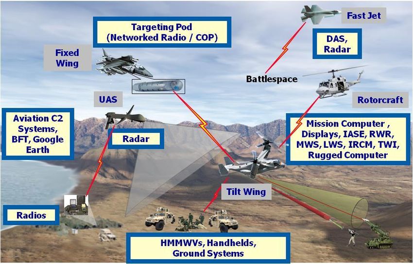
Keynote Paper

                                                       Trends in Electro-Optical Electronic Warfare
                                                  Carl R. Smith, Robert Grasso, Jack Pledger, Naveen Murarka
                                   Northrop Grumman, Electronic Systems, Land & Self Protection Systems Division
                                                                        Rolling Meadows, IL 60008

                                                                                  ABSTRACT

                   Protection of military aircraft from hostile threats is paramount to ensure the survivability of aircrews,
                   platforms, and mission success. While the threat environment continues to become more complex,
                   shrinking defense budgets places new challenges on the development of electronic warfare (EW) systems.
                   This paper presents the trends in electro-optical EW system development including 1) features, 2)
                   affordability, 3) open architecture, 4) multi-functionality, 5) integrated avionics survivability equipment,
                   and 6) enabling technologies for sensors, and optical sources. While these system attributes are not new,
                   they have grown in importance in the design of EW systems. And, if treated correctly can have a
                   beneficial symbiotic relationship to each other and to the airframe they support.

                   1.0        Introduction

                   In the past, more specifically during the Cold War era, development programs were typically large and
                   lengthy development efforts, including platforms like the B-1 (Figure 1), B-2 (Figure 2), missiles such as
                   Minuteman, Pershing, and MX (Figure 3), atomic weaponry (Figure 4), very high energy directed energy
                   (Figure 5), and other large complex and expensive endeavors. Many EW programs during this timeframe
                   struggled to meet program budget and schedule. As an example, the B-1B EW system weighed ~3,000
                   lbs and cost as much as an F-16 of the day. While on this specific platform the airframe, engines, and
                   multi-mode radar systems were all on budget and schedule, the early EW system development
                   significantly overran the budget and unfavorably marked the entire B-1B program. EW systems of the
                   Cold War era often had very lofty performance requirements as part of detailed technical specifications,
                   rather than being performance based to support successful mission completion.

                                    Figure 1. B-1 Bomber [1]                                            Figure 2. B-2 Bomber [2]

                                     Technologies for Optical Countermeasures IX, edited by David H. Titterton, Mark A. Richardson,
                                  Proc. of SPIE Vol. 8543, 854302 · © 2012 SPIE · CCC code: 0277-786/12/$18 · doi: 10.1117/12.978652

                                                                         Proc. of SPIE Vol. 8543 854302-1
Downloaded From: https://www.spiedigitallibrary.org/conference-proceedings-of-spie on 07 Jun 2022
Terms of Use: https://www.spiedigitallibrary.org/terms-of-use
Figure 3. MX Missile [3]                                  Figure 4. Castle Romeo Atomic Weapon Test [4]

                                                                   Figure 5. Airborne Laser (ABL) [5]

                   2.0        Change is Continuous

                   During the Cold War, EW equipment was known as “penetration aids. Their purpose was to get
                   platforms and payloads through elaborate fixed enemy defenses. As time progressed, battlefield, tactics,
                   the enemy, and equipment used in both offensive and defensive capability continually changed. This
                   change, typically driven by technology or innovation, has resulted in what is known as “asymmetric
                   warfare,” where one side’s arsenal and capability differs greatly from the other. Two interesting and
                   historic examples are: 1) the Battle of Crecy in 1346 and 2) the Soviet invasion of Afghanistan during the
                   1980’s. In the battle of Crecy, an army of English longbowmen defeated Genoese crossbowman through
                   the longbow’s superior range and greater rate of fire [6]. The second, and one of the best examples of
                   asymmetric warfare of the century, was the Soviet invasion of Afghanistan where US provided Stinger
                   missiles to the mujahedeen fighters changed the course of the war in favor of Afghanistan [7]. Without
                   question, the Stinger had an immediate military impact. Although initial estimates may have been
                   exaggerated with claims that the Stinger downed an aircraft per day during its first three months of
                   deployment, the missile clearly represented an enormous qualitative improvement in air-defense
                   capability. Previous mujahedeen anti-aircraft technology fielded paled in comparison. The Oerlikon
                   required “twenty mules to transport making the weapon more a liability than an asset [8].” The Blowpipe

                                                                         Proc. of SPIE Vol. 8543 854302-2
Downloaded From: https://www.spiedigitallibrary.org/conference-proceedings-of-spie on 07 Jun 2022
Terms of Use: https://www.spiedigitallibrary.org/terms-of-use
which arrived in 1986, “was a disaster [9]”, during one engagement thirteen missiles were fired at
                   exposed enemy aircraft without a single hit, “a duck shoot in which the ducks won [9].”

                                                    -

                                                    Figure 6. Mujahedeen gunner mounting a Stinger Missile [7]

                   The Stinger missile unquestionably shot down Soviet aircraft at an unprecedented rate in its first few
                   months of use. The final outcome of the Afghan War was the emergence of man portable air defense
                   systems (MANPADS) and their increasing use in the battlespace. MANPADS are low cost, plentiful,
                   easy to use, and highly effective.

                   As technology advances, so does the capability of our adversary’s threat systems. Unlike the Cold War
                   era, today technology advancements are most often driven by commercial and consumer product
                   development applications versus military system development. The computer industry and personal
                   electronic devices are two examples of significantly increased performance, radical size reduction, and
                   multi-functionality, all at a reduced cost and with improved reliability. Implementation of emerging
                   technologies for electro optical EW systems can provide significant capability expansion and performance
                   improvement at a reduced cost. However, technology maturity and implementation risk must be well
                   understood and mitigated by the system design team.

                   4.0        Emergence of the MANPADS Threat

                   MANPADS were originally developed to provide military ground forces protection from enemy aircraft.
                   Notably, they have received a great deal of dubious attention as potential terrorist weapons that might be
                   used against commercial airliners. These threats, affordable and widely available through a variety of
                   sources, have been used successfully over the past three decades both in military conflicts as well as by
                   terrorist organizations.

                   Twenty-five countries, including the United States, produce man-portable air defense systems.
                   Possession, export, and trafficking in such weapons are, officially, tightly controlled due to the threat
                   they pose to civil aviation, although such efforts have not always been successful. Figure 7 shows the
                   evolution of MANPADS threats from the 1960’s towards the future.

                                                                         Proc. of SPIE Vol. 8543 854302-3
Downloaded From: https://www.spiedigitallibrary.org/conference-proceedings-of-spie on 07 Jun 2022
Terms of Use: https://www.spiedigitallibrary.org/terms-of-use
44,0!(1*

                                                                                                                 moog
                                                                                                                  OVA              2020
                                                                                                                                   Dual Band
                                                                                                                        2010       RF /IR Imagers
                                                                                                                        201 Gen
                                                                                                                        Spectral
                                                                                                       2005
                                                                                                                        Imagers
                                                                                                       1S' Gen
                                                                                                       Imagers
                                                                                           2000
                                                                                           Scanning
                                                                                           Imagers
                                                                   1980s & 1990s
                                                                   Cruciform /Rosette
                                                                   Flare CCM
                                                       1970s & 1980s
                                                       Cooled
                                         1960s         Conscan
                                         Spin Scan

                                                          Figure 7. Evolution of MANPADS Threats [18]

                   Typically, the missiles are about 1.8 m (5 to 6 ft) in length and weigh about 18 kg (35 to 40 pounds)
                   depending upon the model. Shoulder-fired surface to air missiles (SAMs) generally have a target
                   detection range of about 10 km and an engagement range of about 6 km, so aircraft flying at 20,000 feet
                   or higher are relatively safe.

                   4.1.1      First Generation Threats

                   First generation MANPADS are the U.S. Redeye, Figure 8, and early versions of the Soviet SA-7, Figure
                   9. All are considered “tail-chase weapons” as their seekers can only acquire and engage after an aircraft
                   has passed the missile’s firing position. Here, the aircraft’s engines are fully exposed to the seeker and
                   provide sufficient thermal signature for engagement. Also, these first generation missiles are highly
                   susceptible to thermal background sources which many may make them somewhat unreliable.

                                Figure 8. U.S. Redeye SAM [19]                                        Figure 9. Soviet SA-7 SAM [20]

                                                                         Proc. of SPIE Vol. 8543 854302-4
Downloaded From: https://www.spiedigitallibrary.org/conference-proceedings-of-spie on 07 Jun 2022
Terms of Use: https://www.spiedigitallibrary.org/terms-of-use
4.1.2      Second Generation Threats

                   Second generation MANPADS such as early versions of the Stinger, Soviet SA-14 [15], Figure 10, and
                   Chinese FN-6 [16], Figure 11, use cooled seekers which enable IR background suppression as well as
                   head-on and side-on engagement capability. These threats may also employ Counter-Countermeasures
                   (CCM) to defeat decoy flares and may have backup target detection modes such as ultraviolet (UV);
                   found on several missiles.

                              Figure 10. Soviet SA-14 SAM [21]                                      Figure 11. Chinese FN-6 SAM [22]

                   4.1.3      Third generation

                   Third generation shoulder-fired SAMs include the Russian SA-18 [17] and the U.S. Stinger B [18],
                   shown in Figures 12 and 13 respectively, may utilize single or multiple detectors to produce a quasi-
                   image of the target and also have flare recognition and rejection capability. While not true imagers they
                   do rely upon the ability to distinguish an extended target from a point target.

                                                                                                                            V Sal

                               Figure 12. Soviet SA-18 SAM [23]                                        Figure 13. Stinger B SAM [24]

                   4.1.4      Fourth generation
                   Fourth generation missiles include the Stinger Block 2, and several missiles believed to be under
                   development in several countries that could incorporate 2D focal plane array guidance systems and other

                                                                         Proc. of SPIE Vol. 8543 854302-5
Downloaded From: https://www.spiedigitallibrary.org/conference-proceedings-of-spie on 07 Jun 2022
Terms of Use: https://www.spiedigitallibrary.org/terms-of-use
advanced sensor systems which will permit engagements at greater range. Conservative estimates place
                   the number of MANPADS threats at over 1,000,000 worldwide [19], making MANPADS the preferred
                   weapon of choice due to their operational simplicity, low cost, availability, and transportability. These
                   threats can be found anywhere high value aircraft operate and truly represent a significant risk to all
                   aircraft.

                   5.0        IRCM Technology and Growth

                   Infrared countermeasure (IRCM) systems can be grouped into two sub-categories, proactive and reactive
                   and include flares, broadband jammers, and directed IRCM. As such, each has its own unique source
                   requirements. Flares, or expendable countermeasures, which act as seduction decoys, are typically used
                   with a missile approach warning sensor to declare the presence of a threat. Flares are then dispensed to
                   decoy the approaching threat away from the target aircraft; Figures 14 and 15 show flares being dispensed
                   from aircraft. Here, it is important to consider that flares, as an expendable countermeasure, have a
                   limited capacity, and, once expended, so is the protection they provide.

                     Figure 14. Large platform expending flares [25]                         Figure 15. Helicopter expending flares [26]

                   Early broadband jammers typically used resistive heater elements (hot bricks) or hyalide arc lamps to
                   provide protection. In this case the source is modulated to deny the threat the ability to optically lock on
                   to the intended target, thus, denying acquisition. Typically, hot brick sources are resistive heated
                   elements which emit in the principal IRCM bands, typically un-modulated, and with the spin-by-carrier
                   provided by a mechanical chopper assembly. These sources are typically employed in older pro-active
                   architectures denying an adversary the ability to make lock on an intended target. Arc lamps are an
                   extension of “hot brick” technology and bridge the operation between both pro-active and reactive
                   architectures. Depending upon architecture, they may have capability to defeat threats pre and post target
                   lock. Figures 16 and 17 depict some typical systems employing resistive heater and arc lamp technology.

                          Figure 16. AN/ALQ-144 IRCM System [27]                                    Figure 17. AN/ALQ-157 IRCM System [28]

                                                                         Proc. of SPIE Vol. 8543 854302-6
Downloaded From: https://www.spiedigitallibrary.org/conference-proceedings-of-spie on 07 Jun 2022
Terms of Use: https://www.spiedigitallibrary.org/terms-of-use
Each system produces a pattern of pulses that is approximately synchronized with the rotation rate of
                   these older seeker reticules. If sufficient energy is provided before the missile locks onto the target, it
                   prevents the operator from firing the missile at the aircraft. If launch occurred, the directed energy steers
                   the missile away from the aircraft and crew.
                   With continued advancement in missile warning sensor (MWS) capability and the ability to achieve high
                   angle-of-accuracy handoff, new concepts in directed infrared countermeasures (DIRCM) became
                   possible. A typical modern day DIRCM system consists of several MWS’s to detect the threat launch; a
                   turret containing a fine track sensor (FTS), and the IRCM source. In operation, the MWS on the platform
                   detects the threat missile launch. Threat position is localized to within a few pixels on this MWS. This
                   data is provided to the DIRCM processor for assessment and threat validation. Upon confirmation of
                   threat, the system processor instructs the turret to slew to the threat position where a FTS contained
                   within the turret acquires the threat and tracks the engagement. Finally, the IRCM source transmits
                   jamming energy, disrupting the missile guidance, resulting in optical break lock and defeat of the
                   incoming threat. Lasers serve as the source of transmitted energy for today’s DIRCM systems.

                   Lasers represent probably the single greatest advancement in IRCM source technology and continue to
                   evolve to meet ever more sophisticated threats. Lasers have been used with great effect in all modern
                   IRCM systems and have evolved from frequency doubled CO2 lasers, to solid state lasers with optical
                   parametric oscillators to generate the wavebands of interest, to semiconductor lasers including optically
                   pumped semiconductor lasers and quantum cascade lasers (QCLs); these last devices represent the next
                   breakthrough in IRCM source technology offering all-band coverage, architectural simplicity, significant
                   reliability over conventional laser approaches and reduced cost. Lasers are typically used in reactive
                   IRCM system where their small beam divergence ensures rapid and effective threat defeat at standoff
                   ranges.

                   The advent of high quality non-linear optical materials enabled solid state lasers to operate in all
                   wavebands of interest, hence, comprising the total IRCM spectrum. These devices signaled a paradigm
                   shift in IRCM away from omni-directional to highly-directional. Figure 18 depicts Northrop Grumman’s
                   VIPER all-band IRCM laser and Figure 19 depicts Northrop Grumman’s latest production DIRCM
                   system showing several missile warning sensors, processor unit, control indicator unit, and mini-pointer
                   tracker assembly with mounted Viper laser.

                      Figure 18. Northrop Grumman Viper Laser [29]                            Figure 19. Northrop Grumman DIRCM [29]

                                                                         Proc. of SPIE Vol. 8543 854302-7
Downloaded From: https://www.spiedigitallibrary.org/conference-proceedings-of-spie on 07 Jun 2022
Terms of Use: https://www.spiedigitallibrary.org/terms-of-use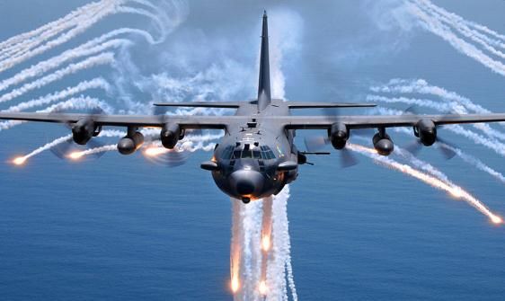
5.0 Aircraft Survivability Equipment

                   EW is often referred to as “Aircraft Survivability Equipment (ASE),” and is no longer just an aid to
                   weapons delivery. Radio frequency (RF) countermeasures and DIRCM are critical subsets of the
                   platform ASE. The lethality of IR mobile and man /portable weapons systems has increased the need for
                   DIRCM. Self protection in this spectrum is nearly mandatory for both non-strike aircraft and combat
                   aircraft. While currently in use on transport aircraft (Figures 20 and 21), reconnaissance aircraft (Figures
                   22 and 23), and combat aircraft and helicopters (Figure 24 and 25), next generation ASE may find itself
                   used on UAVs (Figure 26 and 27) due to their ever increasing cost and as a means to ensure mission
                   success in areas of hostile fire.

                                               ' - \.       \.
                                                    ,/
                           Figure 20. Large Transport Aircraft [10]                                 Figure 21. Large Transport Helicopter [11]

                                      Figure 22. AWACS [12]                                                 Figure 23. Wedgetail [13]

                                      Figure 24. AC-130 [14]                                          Figure 25. Blackhawk Helicopter [15]

                                                                         Proc. of SPIE Vol. 8543 854302-8
Downloaded From: https://www.spiedigitallibrary.org/conference-proceedings-of-spie on 07 Jun 2022
Terms of Use: https://www.spiedigitallibrary.org/terms-of-use
Figure 26. Firescout UAV [16]                                      Figure 27. Globalhawk UAV [17]

                   5.1        Integrated Aircraft Survivability Equipment (IASE)
                   There is an evolving requirement to provide the war fighter with integrated solutions to improve
                   battlespace situational awareness (SA), aircraft survivability, and mission effectiveness. Selectable and
                   actionable data for the aircrew is essential to make critical decisions in theatre. Future IASE will be
                   comprised of system solutions emphasizing modular open system architecture (MOSA), reduced size,
                   weight, and power (SWaP), multi-functionality, and digitally interoperable approaches for data
                   dissemination across the battlefield. System designers must explore solutions to short term requirements
                   via rapid integrations such as enabling threat correlation or mission data recording. Customers and
                   industry will need to work collaboratively to identify mission gaps and potential solutions through trade
                   studies supported by digital modeling and simulation.
                   The ultimate goal is development of platform agnostic, fleet wide solutions whether one is a systems
                   integrator or a sensor/system provider to develop affordable, rapidly deployable effective solutions. At
                   the core of the platform agnostic approach is aircraft survivability. Pilots need to know their aircraft and
                   crew are protected from any hostile threats ranging from SAMs guided by radar, MANPADS, laser
                   guided threats such as beamriders, and hostile fire threats including rocket propelled grenades (RPGs),
                   AK-47s, or anti-artillery aircraft (AAA). Pilots need to be able to plan a mission, fly into their intended
                   objective area, perform their mission, and return to base safely with minimal interruption or risk to their
                   flight due to threat of engagements by hostile forces.

                   Net centric operations and digital interoperability bring SA to the ultimate level. With several advanced
                   systems being deployed, operators are in need of seeing the benefits of these systems across the
                   battlespace. For example, if a terrorist shoots a MANPADS at a helicopter and the on-board system is
                   able to geo-locate the threat, counter it, and act on it, the warfighter must have the option to return
                   counter-fire immediately. Continued effort is required to network the battle space in order to provide the
                   necessary information to the pilot, the troops in the back cabin of a helicopter, to a fixed wing jet flying a
                   close air support mission, to the soldier on the ground, and ultimately to the commander in the Tactical
                   Operations Center (TOC).

                   All of these key points roll into an integrated aircraft survivability suite that is able to ingest aircraft
                   survivability data, correlate, fuse, and identify the threat. This is required to allow the system to optimize
                   the countermeasure, and then push the information to the cockpit display or off-board the information to
                   another platform, as shown in Figure 28.

                                                                         Proc. of SPIE Vol. 8543 854302-9
Downloaded From: https://www.spiedigitallibrary.org/conference-proceedings-of-spie on 07 Jun 2022
Terms of Use: https://www.spiedigitallibrary.org/terms-of-use
Cockpit Mission ' Flare and
Displays Computer Chaff Systems
i
Radar Integrated Laser
Warning Aircraft Warning
Survivability
Cross -cueing Hostile
Sensors
Suite Fire
Controller Indication
Missile Directional
Warning Off - boarding Infrared
Systems information Countermeasures
Figure 28. Integrated Aircraft Survivability Equipment Architecture
As defense budgets continue to shrink, there is a greater need to do more with existing systems. The
challenge is to create exceptional new capabilities while doing so in an affordable manner. By using an
integrated aircraft survivability architecture that relies on software to connect deployed systems and
subsystems, designers are able to meet those needs. Additionally, since there are a declining number of
large programs of records within the industry, system designers need to find innovative ways to showcase
these capabilities. There have been several field exercises and demonstrations conducted across industry
with industry partners and customers working collaboratively together to demonstrate what is possible
with existing systems. Two such demonstrations and field exercises are shown in Figures 29 and Figure
30. As depicted, integrated aircraft survivability is possible today. By using the guiding principles of
MOSA and interoperability, an integrated, affordable solution with improved SWaP is available to the
Warfighter.
Proc. of SPIE Vol. 8543 854302-10
Downloaded From: https://www.spiedigitallibrary.org/conference-proceedings-of-spie on 07 Jun 2022
Terms of Use: https://www.spiedigitallibrary.org/terms-of-use*Simulated
"Surrogate
Interoperability of over 50+ products across multiple nodes UH-1N
Aircraft. Tactical Operations Centers. Vehicles. Dismounts
Government and Industry Collaboration (10 Industry Teammates)
UAS*
AV-8B**
AH-64D*
Live Fire Range
Forward Operating
Base
Improving Situational Awareness
Tactical
Operations Improving Aircraft Survivability
Center Enhancing Mission Effectiveness
Figure 29: Digital Interoperable, Integrated Aircraft Survivability
Proc. of SPIE Vol. 8543 854302-11
Downloaded From: https://www.spiedigitallibrary.org/conference-proceedings-of-spie on 07 Jun 2022
Terms of Use: https://www.spiedigitallibrary.org/terms-of-useFast Jet
Targeting Pod I
(Networked Radio / COP) DAS,
Fixed Radar
Wing
Ba ttlespace
UAS Rotorcraft
Aviation C2
Mission Computer ,
Systems,
Displays, IASE, RWR,
BFT, Google
MWS, LWS, IRCM, TWI,
Earth
Rugged Computer
Radios ._,"
tiet
;°_.a:.
-
HMMWVs, Handhelds,
Ground Systems
Figure 30: Advanced Integrated Aircraft Survivability Equipment
6.0 New Direction: Affordability & Multi-functionality
During the 1980’s and 1990’s, many countries and customers were willing to pay for world class
performance supported by the latest technology. Over time, many cost saving measures were made by
customers to reduce cost and cycle time (e.g. reduction of military specifications, utilization of
commercial components and hardware.) Cost as an independent variable (CAIV) and design to cost
(DTC) started to enter into the system designer’s vocabulary, but never really held the same level of
importance as performance. These changes, while significant at their point in time, do not meet the
current need of our customers. The global economy has had a widespread impact, including the defense
industry. Many countries have experienced, and are forecasting several additional years of economic
hardship or challenge. The US Department of Defense has recently published documents requiring
increased buying power, greater efficiency and productivity in defense spending. These latest initiatives
in acquisition reform will impact everyone in the defense industry.
As a result, we are entering an era of “technically acceptable, lowest cost” for our EW system solutions.
Many future programs will settle for the 80-90% solution to be affordable, meaning the customer will
sacrifice some level of performance for significant cost reduction. Program risk (schedule, cost and
technical performance achievement) is also a key factor. The customer community recognizes that high
risk often results in program cost overruns and schedule extensions, both of which can result in program
cancelation, especially in today’s economic environment.
Future programs will benefit from a modular open system architecture, utilizing industry standard
interfaces. MOSA supports system scalability and allows for spiral upgrades in system performance as
new technology matures to an acceptable level for implementation and fielding. This helps protect the
Customer’s system investment over time so that necessary upgrades are possible to defeat emerging threat
Proc. of SPIE Vol. 8543 854302-12
Downloaded From: https://www.spiedigitallibrary.org/conference-proceedings-of-spie on 07 Jun 2022
Terms of Use: https://www.spiedigitallibrary.org/terms-of-usesystems. Standard interfaces allow more members of industry to compete for the business, naturally
driving prices of components, subassemblies and systems down. The inherent modularity in this
approach allows for common building blocks. Common hardware supports volume discounts in pricing.
The building blocks can be configured for specific platform needs, avoiding over designing/over
performance for some applications while striving for economies of scale from commonality. MOSA also
protects the system designer and Customer from diminishing material source (DMS) issues that naturally
occur over the life of the system.
Multi-functionality is another way to reduce cost and SWaP, while improving reliability. An example of
this is the multi-functionality available from infrared MWS’s. While the primary role of the infrared
MWS is missile warning, the sensor is available for situational awareness when not involved in a missile
engagement, which is most of the time. Through technology infusion and innovation, the same sensor
can be expanded to add laser warning and hostile fire indication (HFI) capability, therefore significantly
reducing SWaP associated with other subsystems on the aircraft. The goal is to accomplish this task in
the same footprint and interface requirements as the original sensor, avoiding very costly aircraft
modifications. An example of this multi-functionality integrated into the volume of previously fielded
MWS is the Advanced Threat Warner (ATW), shown in Figure 31. Innovation will often be the greatest
asset of system designers working on the next generation EW systems.
Figure 31. Northrop Grumman Advanced Threat Warner (ATW)
Other concepts of future technology evolution, supporting affordability and multi-functionality include:
Uncooled sensors for lower cost and improved reliability without significant sacrifice in
performance
Electro-optical steering with large field of regard and broad spectral coverage
Multi-band lasers in an acceptable SWaP supporting DIRCM, laser communication, hostile fire
countermeasures, range finding and targeting applications
Turrets and pointer/trackers for targeting and DIRCM applications
Infrared sensors for missile warning, diminished visual environment (DVE) and situational
awareness
7.0 What’s Next?
As threats evolve, DIRCM systems and their fundamental capability must also advance and be within
affordability limits. Lasers and technologies enabling their development in the area of power and spectral
coverage will be an essential part of this progression. Promising new source technologies include QCLs,
Figure 32, and Femtosecond lasers, Figure 33. QCLs have recently gained tremendous interest in the
DIRCM community given their simple architecture, robustness, direct electrical-to-optical output, and all-
band operation. QCL’s provide high efficiency, excellent beam quality, and a very compact size all at a
very affordable price. Femtosecond lasers can provide tremendous peak power enabling new classes of
Proc. of SPIE Vol. 8543 854302-13
Downloaded From: https://www.spiedigitallibrary.org/conference-proceedings-of-spie on 07 Jun 2022
Terms of Use: https://www.spiedigitallibrary.org/terms-of-useDIRCM, or high energy laser countermeasures (HELCM) to be explored [18, 19]. In this capacity these
sources offer the potential for causing physical damage to the seeker or one of its elements, thus,
defeating the threat. Recent advances in high energy fiber lasers, femto-second pulse lasers, spectral and
spatial beam combining, and atmospheric aberration compensation can make this approach realizable in
the next 5 to 10 years. One major advantage of this concept is the countermeasure technique is threat
agnostic.
Distributed Aperture IRCM (DAIRCM) may replace centralized turrets with several apertures distributed
about the platform. In this capacity, the pointer-tracker and laser aperture are coupled with the MWS thus
eliminating the central turret. A centralized, high power laser with switch, provides power over fiber
optic cable to the multiple sensor locations. Continued advancement in fiber optic cable power handing
capability is expected, and required for this configuration.
Figure 32. Daylight Solutions Aries High Power, Figure 33. Raydiance Ultra-Short Pulse Laser
Multi-Wavelength, QCL [31] [32]
Figure 34. High Energy Laser Countermeasure (HELCM) concept
Two additional concepts are 1.) pre-emptive IRCM and 2.) proactive IRCM. In the case of Pre-emptive
IRCM, the threat is denied the ability to make lock with the target. Pre-emptive represents a true “non-
kinetic” capability where the threat cannot obtain lock on the intended target, sometime referred to as
hostile fire countermeasures (HFCM), or laser dazzling. In proactive IRCM, the threat is detected prior to
launch and countermeasures against the threat are employed.
Proc. of SPIE Vol. 8543 854302-14
Downloaded From: https://www.spiedigitallibrary.org/conference-proceedings-of-spie on 07 Jun 2022
Terms of Use: https://www.spiedigitallibrary.org/terms-of-useFigure 35: Pre-emptive countermeasure concept
8.0 Summary and Conclusions
During the relatively short time that IRCM has been in existence, the threat has continually evolved.
Laser-based DIRCM represented the first real paradigm shift in IRCM capability from omni-directional to
highly directional system solutions. A similar advancement in capability and performance is expected
over the next decade to counter quasi- and full imaging weapon systems. EW systems must advance to
give our war fighter the performance advantage in the battlespace. A clear understanding of the customer
mission and requirements is essential to future success. Innovation supporting less complex solutions to
reduce cost, risk and time to fielding will be critical. System designers must leverage mature and
discriminating technologies whenever possible. Clearly, new and emerging technology will be a key part
of future EW system designs. However, new technology should not be employed without thorough
assessment of risk, and development of a mitigation plan, before implementation. Multi-functionality
supported by technology will be one tool in meeting affordability and SWaP requirements.
Understanding cost drivers at the onset of the design process to support effective trade studies will be
required to meet affordability requirements. To be viable, system solutions must be open architecture to
add additional features, scalable to support specific platform and mission needs, upgradable to defeat
emerging threat systems and affordable to meet budget limitations.
References
1. Rockwell B-1 Lancer, Wikipedia, The Free Encylopedia,
http://en.wikipedia.org/wiki/B-1_Lancer
2. Northrop Grumman B-2 Spirit
http:// http://en.wikipedia.org/wiki/B-2_Spirit
3. LGM-118 Peacekeeper (also known as the MX missile)
http://en.wikipedia.org/wiki/Mx_missile
4. Operation Castle series of American nuclear tests
http://en.wikipedia.org/wiki/Castle_Romeo
5. Airborne Laser
http://en.wikipedia.org/wiki/Boeing_YAL-1
6. Battle of Crécy
http://en.wikipedia.org/wiki/Battle_of_Cr%C3%A9cy
7. An Afghan fighter with a C.I.A.-supplied Stinger missile in late 1987 or early 1988, during the
war against the Soviet Union.
http://thelede.blogs.nytimes.com/2009/05/22/another-stinger-missile-plot-misfires/
8. Stinger missiles in afghanistan
http://defenceforumindia.com/forum/defence-strategic-issues/25041-stinger-missiles-
afghanistan.html
Proc. of SPIE Vol. 8543 854302-15
Downloaded From: https://www.spiedigitallibrary.org/conference-proceedings-of-spie on 07 Jun 2022
Terms of Use: https://www.spiedigitallibrary.org/terms-of-use9. “The New American Interventionism,” Demetrios James Caraley, Columbia University Press,
1999.
10. Boeing C-17 Globemaster III
http://en.wikipedia.org/wiki/Boeing_C-17_Globemaster_III
11. Sikorsky MH-53
http://en.wikipedia.org/wiki/Sikorsky_MH-53
12. AWACS
http://en.wikipedia.org/wiki/Airborne_early_warning_and_control
13. Boeing 737 AEW&C
http://en.wikipedia.org/wiki/Boeing_737_AEW%26C
14. AC-130
http://en.wikipedia.org/wiki/AC_130
15. Blackhawk Helicopter
http://en.wikipedia.org/wiki/Blackhawk_helicopter
16. Fire Scout
http://en.wikipedia.org/wiki/Firescout
17. Northrop Grumman RQ-4 Global Hawk
http://en.wikipedia.org/wiki/Global_Hawk
18. AOC Capital Club Board of Directors Brief, DOD EW S&T, Lt. Col. Karl Dahlhauser, 2005
http://www.myaoc.org/EWEB/images/aoc_library/capitolclub/OSD%20EW%20Briefing/OSDA
OCEWBRIEF.pdf
19. FIM-43 Redeye
http://en.wikipedia.org/wiki/FIM-43_Redeye
20. Strela 2 (SA-7)
http://en.wikipedia.org/wiki/Strela 2
21. Military Analysis Network
http://www.fas.org/man/dod-101/sys/missile/row/sa-14.htm
22. Sinodefence
http://www.sinodefence.com/army/surfacetoairmissile/hongying6.asp
23. Defence Update
http://defense-update.com/products/s/sa-18.htm
24. FM-92 Stinger
http://en.wikipedia.org/wiki/FIM-92_Stinger
25. Scoop, Independent News
http://img.scoop.co.nz/stories/images/0705/594e0f75e4786cadeacf.jpeg
26. EzineMark.com
http://www.google.com/imgres?imgurl=http://img.ezinemark.com/imagemanager2/files/3000369
3/2011/04/2011-04-08-14-47-44-8-a-us-army-black-hawk-helicopter-fires-flares-
as.jpeg&imgrefurl=http://society.ezinemark.com/dramatic-news-in-pictures-march-2011-
7736af319b8e.html&usg=__v7tStCVcmnmxGLaavSM9oqdu0Rc=&h=320&w=480&sz=86&hl=
en&start=9&zoom=1&tbnid=Rx245X9GJvynQM:&tbnh=86&tbnw=129&ei=jyYAUIadBePJ6w
HJ5I20Bw&prev=/images%3Fq%3Dhelicopter%2Bflares%26hl%3Den%26sa%3DX%26rls%3D
com.microsoft:*%26tbm%3Disch&itbs=1
27. AN/ALQ-144 Countermeasure Sets, BAE Systems, PO Box 868, Nashua, NH 03061
www.baesystems.com/BAEProd/groups/public/documents/bae_publication/bae_pdf_eis144a.pdf
28. ALQ-157 Countermeasure Sets, BAE Systems, PO Box 868, Nashua, NH 03061
http://www.aiaa.org/tc/sur/Pages/ALQ-157M.pdf
29. Northrop Grumman, Electronics Systems, Directional Infrared Countermeasures (DIRCM)
Gallery
http://www.es.northropgrumman.com/solutions/nemesis/gallery.html
Proc. of SPIE Vol. 8543 854302-16
Downloaded From: https://www.spiedigitallibrary.org/conference-proceedings-of-spie on 07 Jun 2022
Terms of Use: https://www.spiedigitallibrary.org/terms-of-use30. Northrop Grumman Common Infrared Countermeasures (CIRCM)
http://www.es.northropgrumman.com/circm/
31. Daylight Solution Aries™ Series - High Power, Multi-Wavelength Mid-IR Laser Systems
http://www.daylightsolutions.com/products/lasers/aries.htm
32. Raydiance
http://www.raydiance.com/our-technology
33. Laser Dazzling of Infrared Focal Plane Array Cameras, Ric Schleijpen, SPIE Newsroom,
10.1117/2.1200803.01118 (2008)
Proc. of SPIE Vol. 8543 854302-17
Downloaded From: https://www.spiedigitallibrary.org/conference-proceedings-of-spie on 07 Jun 2022
Terms of Use: https://www.spiedigitallibrary.org/terms-of-useYou can also read