Comparative Study of Energy Absorption Capability of Flat Plate Coupons Made by CFRP Plain Weave Fabric Composites
←
→
Page content transcription
If your browser does not render page correctly, please read the page content below
World Journal of Mechanics, 2021, 11, 121-145
 https://www.scirp.org/journal/wjm
 ISSN Online: 2160-0503
 ISSN Print: 2160-049X

Comparative Study of Energy Absorption
Capability of Flat Plate Coupons Made by
CFRP Plain Weave Fabric Composites

Redouane Lombarkia1*, Augustin Gakwaya1, Denis Nandlall2, Marie-Laure Dano1,
Julie Lévesque1, Ameur BenKhelifa1, Philippe Vachon-Joannette1, Philippe Gagnon1

Department of Mechanical Engineering, Université Laval, Québec, Canada
1

Canada Defence Research & Development Canada, Valcartier, Québec, Canada
2

How to cite this paper: Lombarkia, R., Gak- Abstract
waya, A., Nandlall, D., Dano, M.-L., Lévesque,
J., BenKhelifa, A., Vachon-Joannette, P. and Despite years of governmental and academic institutions’ researches, no ex-
Gagnon, P. (2021) Comparative Study of perimental standards are established for evaluating crush Specific Energy
Energy Absorption Capability of Flat Plate
 Absorption SEA for plain weave fabric woven carbon-fiber-reinforced com-
Coupons Made by CFRP Plain Weave Fab-
ric Composites. World Journal of Mechan- posites used in modern aircraft structures as elements of the boxes to mitigate
ics, 11, 121-145. damage during crush events. At the laboratory scale, this paper proposes a
https://doi.org/10.4236/wjm.2021.117010 comparative study of energy absorption capability of flat plate coupons made
Received: May 4, 2021
 by CFRP plain weave fabric composites. A new fixture design and setup were
Accepted: July 4, 2021 created with hydraulic pressure and drop tower machines to carry out tests of
Published: July 7, 2021 flat plate composite specimens under quasi-static and low velocity on-axis
 crash loading. For investigating parameters sensibility of triggers and layups,
Copyright © 2021 by author(s) and
Scientific Research Publishing Inc. numerical and experimental results of four trigger types and three stacking
This work is licensed under the Creative sequences were compared. A confrontation between experimental and pre-
Commons Attribution International developed UL-Crush numerical material model results confirms that coupons
License (CC BY 4.0).
http://creativecommons.org/licenses/by/4.0/
 with 0˚ oriented central plies and saw teeth or corrugated triggers dissipates
 Open Access higher energy during crush, compared to coupons with 90˚ or 45˚ oriented
 central plies and chamfer 45˚ or steeple triggers. An efficient and simplified
 experimental methodology was developed to measure and investigate differ-
 ent parameters influencing SEA of composites under crush load. Comparison
 between experimental and UL-Crush material model confirms the perform-
 ance of such simulation tool.

 Keywords
 Crush Behavior, Triggers, Damage and Failure Mechanisms, Crashworthiness,
 SEA

DOI: 10.4236/wjm.2021.117010 Jul. 7, 2021 121 World Journal of Mechanics
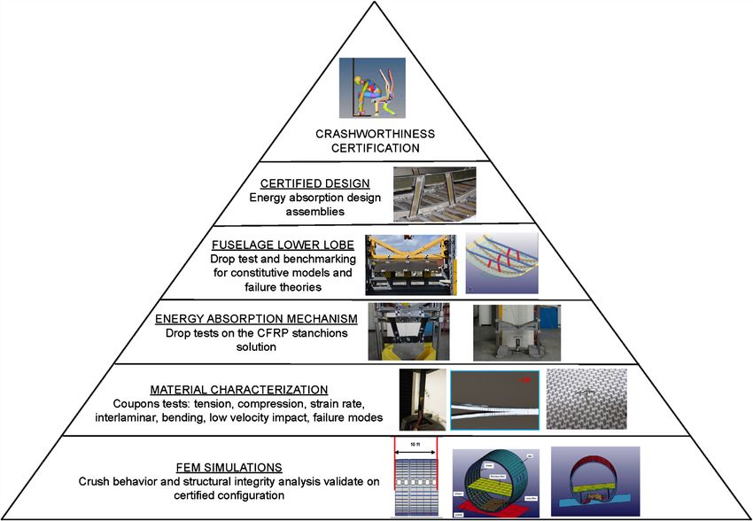
R. Lombarkia et al.

 1. Introduction
 Structural energy absorbers can be found in all modern vehicles in the form of
 collapsible floor stanchions and beams in aircraft subfloor and cargo structures
 [1], and in the form of collapsible tubular rails in the front end of passenger cars.
 FAA (Federal Aviation Administration) issued Advisory Circular AC 20-107B
 “composite aircraft structure” based on the researches on composite aircraft
 structures involving fiber-reinforced materials. The FAA requires an assessment
 of each new aircraft design regarding crashworthiness performance, i.e. its abil-
 ity to protect its occupants during a crash event.
 Aircraft manufacturers are currently using numerical simulations in the proc-
 ess of designing, testing, and certifying aircraft parts such as seats, wings…. fol-
 lowing the building block approach as shown in Figure 1.
 With the advancement made in computing technologies, Finite Element
 simulations have become an important tool to predict crush behavior by using
 high performance material models, [3]. Modeling aircraft components crush re-
 sponse is already involved in different explicit nonlinear dynamic finite element
 codes such as ABAQUS, PAM-CRASH, LS-DYNA, DYNA3D, and MSC. Dy-
 tran, [4].
 Virtual testing should consider various aspects:

Figure 1. Building block approach [2].

DOI: 10.4236/wjm.2021.117010 122 World Journal of Mechanics
R. Lombarkia et al.

 1) A precise comprehension of the scenario of crush in term of damage mecha-
 nisms sequence,
 2) Appropriate representation of each damage mechanism in form of criteri-
 ons within constitutive and kinematic laws of the material,
 3) Identification of each parameter with the continuous improvements of the
 measurement and inspection techniques [5] [6], and validation of the developed
 computational tools [7].
 To assist predictive simulation tools for crush of composite parts, more fun-
 damental experimental test methods are needed for model validation, other spe-
 cific experiments are also necessary for identification of the different input pa-
 rameters of the crush material model.
 Compressive failure mode is complex as it involves several interacting failure
 mechanisms, such as micro buckling, kink-bandings, fragmentation and de-
 lamination. Furthermore, the material response can be sensitive to fabrication
 defects and imperfections. In general, predicting the response of structures sub-
 jected to severe compressive loads is even more challenging than predicting their
 tensile response [8].
 Crush load as compressive load is complex and some factors contributing to
 this complexity have been identified: a) the large strains and rotations involved;
 b) the interaction of complex damage mechanisms; c) significant geometric trans-
 formations in the crushing zone; d) material nonlinearity; e) contact and friction
 and f) potential strain rate effects [9].
 Crush behavior of composite materials has been observed to depend on a large
 number of factors such as the trigger types, the scale and cross section of cou-
 pons, the layups and the fiber architecture [10] [11] [12] [13] [14].
 In order to compare crush behavior of materials, most authors use the SEA
 calculation as a main metric evaluated from crush tests. Unfortunately, there is
 no standardized test method for assessing the SEA coefficient, and research ef-
 forts can not be directly compared because different test methods are used in
 several works. However, some efforts are being made by the Crashworthiness
 Working Group of the CMH-17 [15], with the ASTM International Committee
 D-30 in order to arrive at establishing some standards. Similarly, the Energy
 Management Working Group of the ACC [16], government organizations such
 as the US National Aeronautics and Space Administration (NASA) [17], the
 German Aerospace Center (DLR) [18], and the National Aerospace Laboratory
 of the Netherlands (NLR) [19], have also dedicated resources aimed at the set up
 of standard experimental characterization process of composite crush energy
 absorption [1]. Usually, thin-walled tubular specimens rather than flat coupons
 or other shapes have been used for SEA measurements and crush energy inves-
 tigations. Tubes were selected because they are self-supporting and therefore do
 not require special fixtures, and they are commonly used in automotive crush
 structures. Some of the observed results reported by authors are contradictory
 and questions remain how exactly certain parameters influence results [1].

DOI: 10.4236/wjm.2021.117010 123 World Journal of Mechanics
R. Lombarkia et al.

 To avoid complicated coupling between such factors, in the aim of character-
 ising material parameters, validating constitutive material model and SEA meas-
 urement, an alternative approach is then to use a flat plate material coupon, with
 the advantage of being easily manufactured with no requirement for special
 tooling. However, anti-buckling fixture for supporting the flat coupon without
 inducing friction or suppressing crush failure and preventing catastrophic failure
 is often required [20] Figure 2.
 Several other anti-buckling fixtures for flat coupons crush testing have been
 proposed over the years, and a good review is provided by [1] Figure 3.
 Such fixtures require an unsupported height at the crush front where material
 bend and form fronds, and debris are evacuated.
 The free unsupported height of specimens may influence the precision of the
 calculated SEA and crushing stress. An optimised free height has been found to
 be compromised between (3.2 - 12.8 mm) for SEA measurements and between
 (10 - 25 mm) for crushing stress measurements [1].
 Other fixtures for flat coupons have also often been adopted with no anti-buckling
 system by minimizing the free unsupported height of specimens to capture necessary
 crush behavior; force peak and sustainable post peak load, Figure 4.
 Many Researches works confirms that the modulus and strength of compos-
 ites increases with strain rate and that the dependency on the strain rate is

 Figure 2. Flat coupon crush test fixture from [20].

 Figure 3. Flat coupon crush test fixtures from (a) NASA, [17]; (b) Engenuity, [15]; (c)
 Oakridge National Laboratory [19].

DOI: 10.4236/wjm.2021.117010 124 World Journal of Mechanics
R. Lombarkia et al.

 Figure 4. Flat coupon crush test fixtures from [21].

 driven by matrix material [3].
 Matrix semi-crystalline thermoplastic resins (such as polycarbonate) offer ad-
 vantages compared to conventional thermosetting resins (such as epoxies); and
 these includes better chemical resistance, temperature resistance and impact re-
 sistances, and they may be used for aircraft applications.
 In order to test different crash scenarios under different strain rates, various
 test machines are utilized:
 For quasi-static tests, from 10−2 to 10−3 s−1, simple hydraulic pressure machine
 can be used with different fixture systems.
 For low velocity tests, with strain rates ranging from 1 to 102 s−1, specialized
 machines such as drop towers (e.g. Instron 9340) should be utilized for measur-
 ing the impact energy absorption capacity as well as the damage initiation and
 propagation [22]. Used a modified off-axis compression fixture set-up to carry
 out tests on carbon fiber reinforced coupons under quasi-static and low velocity
 compression by using an MTS Criterion series40 Loading frame and drop tower
 facility.
 For high velocity tests, with strain rates ranging from 102 to 104 s−1, experi-
 ments can be achieved using a split Hopkinson pressure bar [23], such tests re-
 quire the use of high-speed videography [24].
 For very high velocity tests, with strain rates ranging from 104 to 106 s−1, ex-
 periments can be achieved using the acceleration of projectiles or the detonation
 of explosives [25].
 The scope of the present work is limited to damage occurring in compression
 for quasi-static and low velocity compression tests with strain rates ranging from
 10−2 to 102 s−1.
 The originality of this paper concerns the establishment of a simple experi-
 mental method and design of setup and fixture to be installed within a drop

DOI: 10.4236/wjm.2021.117010 125 World Journal of Mechanics
R. Lombarkia et al.

 tower to perform crush tests of small flat plate composites coupons in the aim of
 investigating the QS and dynamic responses during crush loading.
 Hence, a comparative study is conducted to evaluate the influence of the trig-
 ger geometry, layups and strain rates on the crushing response by selecting four
 trigger types, three layups and two strain rates.
 For in plane crushing, the objectives are: 1) to observe how triggers can im-
 prove coupons stability during the crushing process, and 2) how damage mecha-
 nisms, such as fragmentation, delamination and kink bandings can be exploited
 to achieve a high amount of absorbed compressive energy.
 Moreover, the boundary conditions of the tests and the damage growth
 observed from video recordings and microscopic inspections will be dis-
 cussed.
 Twenty-four CFRP plain weave fabric composite flat plate coupons were carried
 out with variations in stacking sequences, strain rates and trigger types, using new
 setups, multiple measurements and inspection instrumentations for a better dam-
 age mechanisms and energy absorption investigation, providing relevant guide-
 lines to identify future research directions. The plan of the paper is as follows:
 Section 2 deals with the experimental procedures and coupons preparation.
 Section 3 provides a presentation of experimental results while Section 4 gives a
 general presentation of the numerical simulation and pre-developed material
 constitutive model. In Section 5, a discussion about experimental results and a
 comparison between numerical and experimental results are presented, and fi-
 nally, section 6 gives conclusion.

 2. Experimental Work
 The first goal of the experimental work is the investigation of the energy ab-
 sorbing capability of flat plate coupons made from plain weave fabric composite
 in order to validate numerical modeling methodology following Building Block
 Approach. A systematic experimental investigation is conducted to evaluate the
 influence of the trigger geometries, layups and strain rates on the crushing re-
 sponse. Quasi-static and dynamic crush experiments in which one parameter is
 tested while keeping all other testing parameters constant are carried out. From
 the obtained results, the best material configuration to achieve more energy dis-
 sipation will be established.
 The material system selected for this study is plain weave (PW) fabric carbon
 fiber/epoxy prepreg supplied by Bell Helicopter Textron Company (BHTC).
 Such material is used extensively for general aviation primary structures.
 1) Machine of tests and instrumentations
 For quasi-static tests, the MTS Criterion Series 40 universal machine is used
 with setup and fixture as shown in Figure 7.
 For low velocity crush tests, the test system, Figure 5, is formed of drop tower
 CEAST Instron9340 and setup with fixture installed within the inferior enclo-
 sure of the drop tower. Composite flat plate coupon is clamped at the end of the

DOI: 10.4236/wjm.2021.117010 126 World Journal of Mechanics
R. Lombarkia et al.

 fixture fixed into the setup. A metal mass (net weight of 22.5 kg) is added to
 achieve the necessary crushing energy. An impactor of diameter 22.5 mm trans-
 lates along Z vertical axis to transmit load to the setup and to the coupon.
 The used setup, Figure 6, has been designed and manufactured within the

 Figure 5. Drop Tower CEAST Instron9340 with developed setup and fixture.

 Figure 6. Setup for QS and Dynamic crush tests to insert into enclosure Cell of drop
 tower.

DOI: 10.4236/wjm.2021.117010 127 World Journal of Mechanics
R. Lombarkia et al.

 M3C Laboratory (Mechanical Engineering Department of Université Laval). It is
 composed of two fixed plates and two vertical translational plates, and an M1404
 Series PCB piezo electrical Load Cell has been added at the bottom of setup to
 capture crush forces.
 Different fixtures may be added to clamp different geometries of composite
 coupons. A fast Camera, GOM Aramis Digital Image Correlation DIC and video
 extensometer have also been added to measure displacement of specimens,
 2) Tests campaigns
 Two different test campaigns were performed to collect data:
 - The 1st session of tests with flat plate specimens were concerned with QS
 crush tests using the MTS Criterion series 40 machine, Figure 7, with the new
 setup and fixture.
 - The 2nd session of tests were carried out with Instron9340 drop tower with
 new setup and fixture for low velocity crushing.
 The composite material adopted in this study is BHTC_PW_T650_7264, es-
 pecially prepared for the CRIAQ Comp-410 project, which is a research project
 in partnership with Bombardier and BHTC. The material used is a plain weave
 PW woven-ply Carbon fiber reinforced epoxy thermoset matrix. Fabric is con-
 structed from yarns in which fibers are bundled or twisted into threads. The
 density is 1527 Kg/m3. Each Composite ply should have a thickness of 0.203 mm.
 The required plies number of plain fabrics is eight.
 The standards for characterization tests were developed for composite materi-
 als with unidirectional architecture. No standard exists to date for composite

 Figure 7. MTS criterion 40 series electromechanical universal test systems.

DOI: 10.4236/wjm.2021.117010 128 World Journal of Mechanics
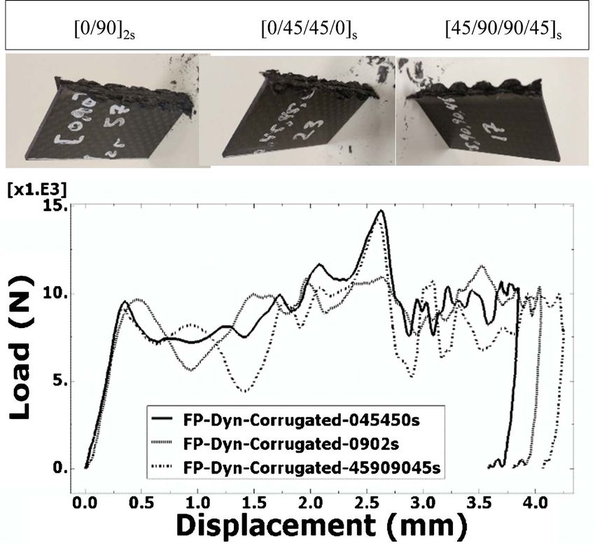
R. Lombarkia et al.

 materials with woven architecture. However, other research groups around the
 world have already performed characterization tests on woven materials using
 the standards defined for unidirectional fiber composite materials [26] [24].
 Experimental tests objective is to measure the sensitivity of different parame-
 ters by selecting four trigger types; steeple, chamfer 45˚, corrugated and saw
 teeth. Different stacking sequences; [0/90]2s, [0/45/45/0]s and [45/90/90/45]s were
 also tested, and two crush velocities; 3 mm/min and 4650 mm/s were used.
 Figure 8 shows the geometries of flat plate coupons with saw teeth, corru-
 gated, steeple and chamfer 45˚ triggers. In total, 24 samples were tested.
 Flat plates are preferred for simple crush tests, because they are less sensitive to
 warping compared to other open section coupons with the presence of torsion by
 the eccentric forces, or in the presence of the instabilities in compression loads. In
 all cases, in the design of these sections, the phenomenon of warping is crucial.
 3) Boundary conditions
 A lateral support is added to prevent global buckling of specimens during
 crushing. The coupon is clamped between two aluminium 6560 metal blocks.

 Figure 8. Flat plate coupons dimensions; (a): with saw teeth trigger; (b): with corrugated
 trigger; (c): with steeple trigger; (d): with Chamfer 45˚ trigger.

DOI: 10.4236/wjm.2021.117010 129 World Journal of Mechanics
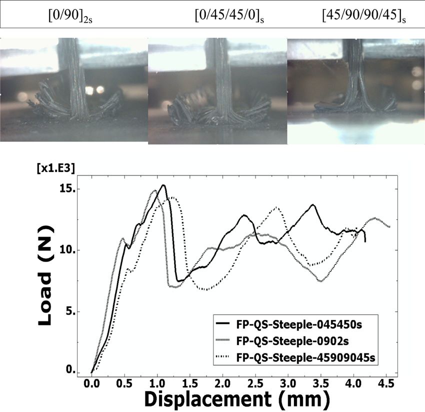
R. Lombarkia et al.

 Boundary conditions consists of friction between aluminum blocks and the
 composite coupon and friction between the front steel plate and the composite
 coupon, damage can occur if excessive clamping forces are used and frictionless
 contact between Aluminum clamps and composite coupons is also eliminated to
 avoid possible lateral movement. The coefficients of friction can be evaluated
 with the ASTM standards.
 A coefficient of friction of 0.15 is used for the contact between steel fixed plate
 and composite coupon in crush front. Between the aluminum clamps and coupon,
 a friction coefficient of 0.2 is chosen. The constant width of the coupons is 50.8 mm
 and the free unsupported height was chosen for 10 mm in order to avoid global
 buckling phenomenon. The cross-section surface of specimens is thus 82.5 mm2.
 The free height of the specimens is a crucial parameter that was determined be-
 fore the present work during the design stage of an optimised height for crush tests.
 Figure 9 shows the boundary conditions adopted for the present experimental
 work. For QS conditions, tests were stopped manually after 4 to 8 mm of crashed
 material stroke distance. However, for Low Velocity crush conditions, tests were
 stopped automatically, because the amount of energy delivered by drop tower
 was limited to crush a maximum of 6 mm height of composite coupons. The
 progression of the crushing event was monitored using instrumentation facili-
 ties, such as GOM DIC Aramis, fast camera and extensometer. Some coupons
 were prepared for optical microscopic observations.

 3. Experimental Results
 1) 1st Tests campaign: Quasi static Crush Results:
 Quasi-static compression tests were carried out at 3 mm/min of compression
 speed during 4 to 8 mm of stroke distance using a universal MTS Criterion Se-
 ries 40 pressure test machine. Figure 10, Figure 11 & Figure 12 show final
 crush fronts. Fragmentation increases for coupons with [0/45/45/0]s Layup, and

 Figure 9. Flat plate coupon fixture boundary conditions. The illustration shows a coupon
 with corrugated trigger.

DOI: 10.4236/wjm.2021.117010 130 World Journal of Mechanics
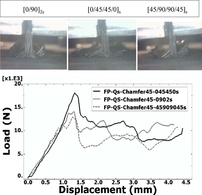
R. Lombarkia et al.

 delamination increases for coupons with [45/90/90/45]s Layup.
 For [0/90]2s Layup:

 Figure 10. QS crush tests results for [0/90]2s Layup: (a) flat plate coupon with Chamfer
 45˚ trigger; (b) steeple trigger; (c) corrugated trigger; (d) saw teeth trigger.

 For [0/45/45/0]s Layup:

 Figure 11. QS crush tests results for [0/45/45/0]s Layup: (a) flat plate coupon with Cham-
 fer 45˚ trigger; (b) steeple trigger; (c) corrugated trigger; (d) saw teeth trigger.

 For [45/90/90/45]s Layup:

 Figure 12. QS crush tests results for [45/90/90/45]s Layup: (a) flat plate coupon with
 Chamfer 45˚ trigger; (b) steeple trigger; (c) corrugated trigger; (d) saw teeth trigger.

DOI: 10.4236/wjm.2021.117010 131 World Journal of Mechanics
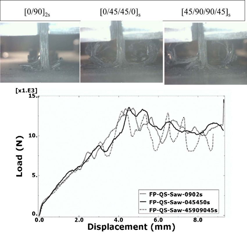
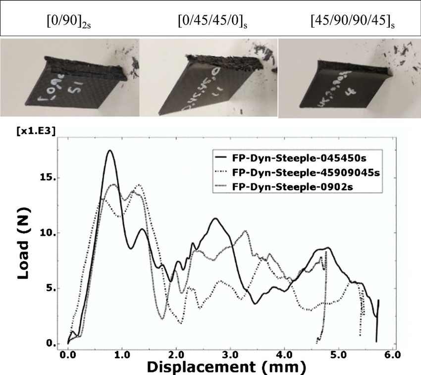
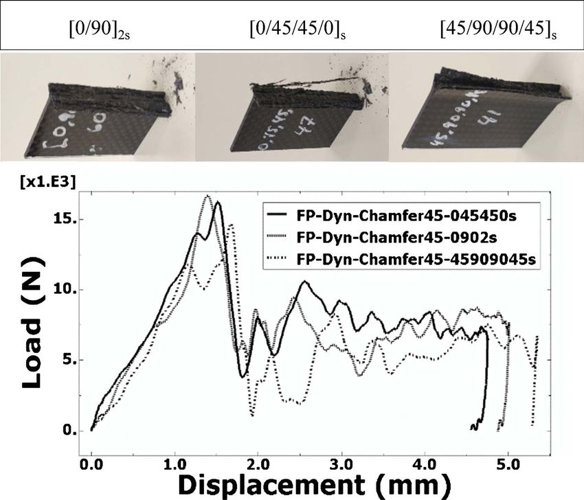
R. Lombarkia et al.

 2) 2nd Tests campaign: Low Velocity Crush Results:
 Dynamic compression tests were performed at 4650 mm/s of compression
 speed during 6 mm of stroke distance using drop tower Instron9340 facility.
 Figure 13, Figure 14 & Figure 15 show post-mortem coupons illustrating com-
 bined splaying and fragmentation crush mode. As above, fragmentation in-
 creases for coupons with [0/45/45/0]s layup, and delamination increases for
 coupons with [45/90/90/45]s layup.
 For [0/90]2s Layup:

 Figure 13. Dynamic crush tests results for [0/90]2s Layup: (a) flat plate coupon with
 Chamfer 45˚ trigger; (b) steeple trigger; (c) corrugated trigger; (d) saw teeth trigger.

 For [0/45/45/0]s Layup:

 Figure 14. Dynamic crush tests results for [0/45/45/0]s Layup: (a) flat plate coupon with
 Chamfer 45˚ trigger; (b) steeple trigger; (c) corrugated trigger; (d)saw teeth trigger.

 For [45/90/90/45]s Layup:

 Figure 15. Dynamic crush tests results for [45/90/90/45]s Layup: (a) flat plate coupon
 with Chamfer 45˚ trigger; (b) steeple trigger; (c) corrugated trigger; (d)saw teeth trigger.

DOI: 10.4236/wjm.2021.117010 132 World Journal of Mechanics
R. Lombarkia et al.

 The absorbed energy by the specimen during crushing is equal to the area be-
 neath the load-displacement curve, and could be calculated by the equation:
 l
 Ae = ∫ P ( z ) dz (III-1)
 0

 where z is the stroke, and P is the applied load
 The SEA is equal to the absorbed energy per unit of crushed specimen mass,
 and could be defined by the equation:
 l

 A
 ∫ P ( z ) dz
 = =
 SEA 0
 (III-2)
 ρ Al ρ Al
 where ρ is the density, A is the cross section area of specimen.
 For the QS tests, the different applied load P vs. the stroke z curves are shown
 in the following; Figure 16 to Figure 19.
 For the Dynamic tests, applied load vs. stroke curves are shown in Figure 20
 to Figure 23.

 4. Numerical Modeling
 In order to verify a pre-developed numerical tool UL-Crush, [27], an explicit 3D
 crush analysis of flat plate coupon was carried out within Abaqus2020. The nu-
 merical model is shown in Figure 24 with finer mesh. Some simplifications were

 Figure 16. Load P vs. the stroke z for QS crush tests of steeple trigger coupons.

DOI: 10.4236/wjm.2021.117010 133 World Journal of Mechanics
R. Lombarkia et al.

 Figure 17. Load P vs. the stroke z for QS crush tests of saw teeth trigger coupons.

 Figure 18. Load P vs. the stroke z for QS crush tests of corrugated trigger coupons.

DOI: 10.4236/wjm.2021.117010 134 World Journal of Mechanics
R. Lombarkia et al.

 Figure 19. Load P vs. the stroke z for QS crush tests of chamfer 45˚ trigger coupons.

 Figure 20. Load P vs. the stroke z for Dyn crush tests of steeple trigger coupons.

DOI: 10.4236/wjm.2021.117010 135 World Journal of Mechanics
R. Lombarkia et al.

 Figure 21. Load P vs. the stroke z for Dyn crush tests of saw-teeth trigger coupons.

 Figure 22. Load P vs. the stroke z for Dyn crush tests: corrugated trigger coupons.

DOI: 10.4236/wjm.2021.117010 136 World Journal of Mechanics
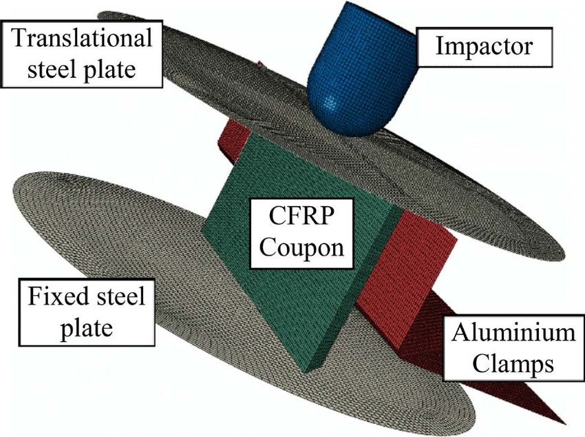
R. Lombarkia et al.

 Figure 23. Load P vs. stroke z for Dyn crush tests: Chamfer 45˚ trigger coupons.

 Figure 24. Simplified experimental fixture modeled within Abaqus simulation environ-
 ment.

 adopted to reduce the computational time. Steel solid fixed and translational
 plates are simplified to Steel shells, Aluminum solid clamps are also simplified to
 Aluminum shells. Fixed analytically rigid bodies are placed on the bottom, and
 largest vertical sides of the coupon. The friction coefficient between the coupon
 and the steel rigid bottom body is 0.15, and between the coupon and the alumi-
 num clamps is 0.2.
 The loading was introduced by applying to the top steel plate, a vertical con-
 stant velocity of 3 mm/min for QS and vertical initial velocity of 4650 mm/s for
 dynamic tests.

DOI: 10.4236/wjm.2021.117010 137 World Journal of Mechanics
R. Lombarkia et al.

 This modeling approach considers one layer of solid elements per one real ply
 of laminate. Solid elements with reduced integration (C3D8R) were used to
 mesh the intra composite plies. To model the behavior of interface between
 plies, COH3D8 cohesive elements were used.
 Abaqus/Explicit offers Hourglass and distortion control to prevent solid ele-
 ments from inverting or distorting excessively for these cases. If distortion con-
 trol is used, the energy dissipated by distortion control can be output upon re-
 quest, [28]. UL-Crush constitutive material model was affected to the C3D8R
 elements.
 The constitutive model of a material system is the relation between physical
 properties to describe behavior of the system under loading and boundary con-
 ditions.
 UL-Crush 3D constitutive model, [27], implemented as user subroutine VUMAT,
 used for modeling plies has been developed to predict behavior of plain weave fabric
 woven CFRP composites, which is an improvement of Abq_ply_Fabric 2D material
 model embedded within the commercial code Abaqus/Explicit [28].
 Abq_ply_Fabric has the potential to sustain a progressive stiffness degradation
 and provides a homogeneous orthotropic linear elastic formulation with damage
 initiation and evolution laws. Such laws based on fracture energies ensure that
 the correct amount of energy dissipates [29] [30] [31] [32].
 UL-Crush 3D material model enhances 2D Abq_Ply_Fabric model by adding
 a modified Hashin 3D failure criteria, kin-banding modeling, fragmentation for-
 mulation and strain rate sensitivity modeling [27].
 The simulations were performed using node in Calcul-Québec Cedar super-
 computer with Abaqus/Explicit and domain parallelization.

 5. Discussion
 After analysing different experimental results and the loads vs. stroke curves, it
 was observed that the crush mode observed is a hybrid splaying-fragmentation
 mode. The coupons with [0/45/45/0]s layup achieves a high amount of compres-
 sive fragmentation failure due to 0 degree internal plies ability to fragment under
 the crush load. For dynamic crushing, the coupons seem to present internal dis-
 integration involving less absorbed energy compared to quasi static crushing
 [22]. The type of triggers has a strong influence on the compressive response; the
 new proposed corrugated trigger improves the specimen stability during the
 crushing tests.
 It has been also observed that the corrugated teeth trigger increases the amount
 of dissipated energy of the coupons, especially in QS case, due to the multiplica-
 tion of damage mechanisms during the first period of crushing the height of the
 trigger.
 The different amounts of SEA are presented in Table 1. The largest calculated
 SEA is highlighted in the table and is equal to 0.1289 Joule/mm3. It is related to
 the coupon with [0, 45, 45, 0] layup, corrugated trigger and QS test case.

DOI: 10.4236/wjm.2021.117010 138 World Journal of Mechanics
R. Lombarkia et al.

 Figure 25 illustrates the classification of different crush tests. SEA for QS tests
 are clearly higher than SEA for low velocity tests. Coupons are classified regard-
 ing SEA amounts calculated respectively from higher to lower; with [0/45/45/0]s,
 [0/90]2s and [45/90/90/45]s layups, and with corrugated, steeple, chamfer 45˚ and
 saw teeth triggers.
 The Delamination was one of the major damage mechanisms observed during

 Table 1. Comparison between measured SEA amounts for crush tests.

 Layups Triggers SEA (Dyn) Joule/mm 3 SEA (QS) Joule/mm 3

 steeple 0.0787 0.1181

 saw 0.0769 0.1065
 [45, 90, 90, 45]s
 Corrugated 0.0990 0.1213

 Chamfer 45˚ 0.0741 0.0996

 steeple 0.0903 0.1148

 saw 0.0877 0.1209
 [0, 45, 45, 0]s
 corrugated 0.1190 0.1289

 Chamfer 45˚ 0.0903 0.1212

 steeple 0.0993 0.1183

 saw 0.0787 0.1094
 [0, 90]2s
 corrugated 0.1130 0.1210

 Chamfer 45˚ 0.0921 0.1120

 Figure 25. Chart comparison for specific energy absorption of crush tests.

DOI: 10.4236/wjm.2021.117010 139 World Journal of Mechanics
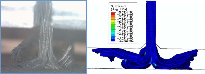
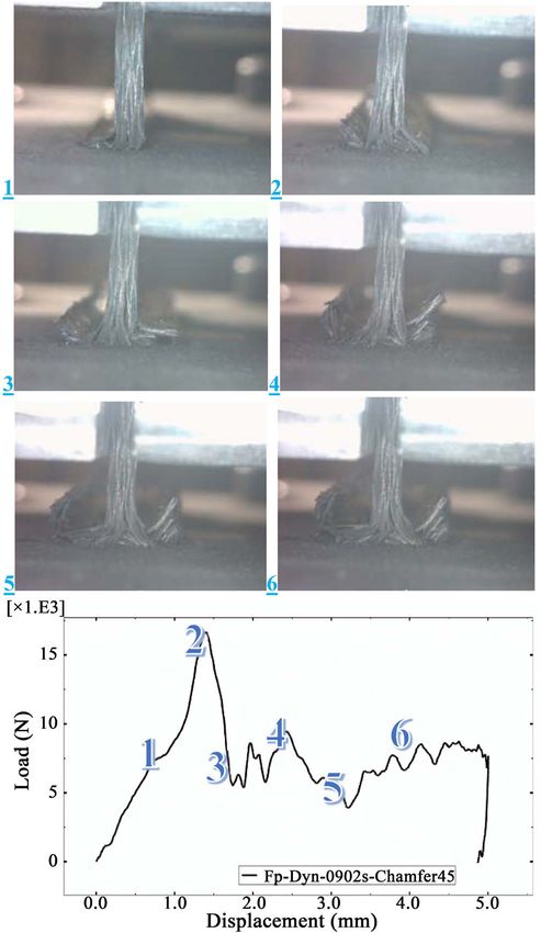
R. Lombarkia et al.

 crush of flat plate coupons. All types of triggers produce a local stress concentra-
 tion, resulting into the initiation of delamination or splaying failure mode. In
 real crush event, Mode I, Mode II and Mode III fracture are usually coupled and
 combined with a complex delamination mode.
 The first effect of crush was characterized by a peak force, followed by a load drop,
 associated with a delamination damage mechanism. The second effect of crush was a
 steady state crushing load period. The ratio between sustainable load and peak force
 was slightly less then one, for coupons with saw teeth and corrugated trigger, and
 between 0.5 and 0.8 for coupons with chamfer 45˚ and steeple trigger.
 Figure 26 shows different steps of crushing and corresponding positions in
 Load vs Displacement curve. The first drop in the curve (from position 2 to 3) is
 the result of delamination and of the decrease of total supporting surface in the
 crush front.

 Figure 26. Crush scenario and Load P vs. stroke z for crush test of coupon with Chamfer
 45˚ trigger and [0/90]2s layup.

DOI: 10.4236/wjm.2021.117010 140 World Journal of Mechanics
R. Lombarkia et al.

 External fronds or petals resulting from delamination fails but remain at-
 tached to the central body of the coupon due to the braided architecture of plain
 weave fabric.
 Internal plies produce fragments in the crush front and the accumulation of
 debris between delaminated plies and steel rigid wall stiffens the coupons and
 contributes to the sustainability of high level of post peak stable crush load in-
 volving to supplemental energy absorption. In addition, internal fragments push
 external plies to delaminate and reproduce the same cycle of crush scenario.
 A delay was observed between the load vs. stroke curves. First for coupons
 with 45˚ chamfer trigger and steeple trigger and then for coupons with saw teeth
 trigger and corrugated trigger, the long period to reach the steady state crushing
 load can be partially attributed to the difference of time for steel wall to be in
 contact with the entire cross section of the flat plate coupon and the difference of
 trigger heights. The height of chamfer 45˚ and steeple trigger is 1.624 mm com-
 pared to 5 mm for saw teeth and corrugated trigger.
 Figure 27 shows a comparison between Experimental, Abq_Ply_Fabric and
 UL-Crush dynamic results for flat coupon with [0/90]2s layup and chamfer 45˚
 trigger type, with the new fixture designed for this study.
 The numerical curves of Abq_Ply_Fabric and UL-Crush has a SAE600 filter-
 ing operator with 600 Hz filter applied to smooth out the numerical prediction.
 Abq_Ply_Fabric seems to capture peak force but sur-estimate the sustainable
 post peak crush load. However, UL-Crush capture well the post peak crush load
 and under-estimate peak force.
 Figure 28 shows a comparison of damages occurred after crush test between
 the experimental and the UL-Crush 3D material model simulation results for flat
 coupon with [0/90]2s layup and chamfer45˚ trigger type.

 6. Conclusions
 In order to evaluate and compare crushing behavior of aerospace grade composite

 Figure 27. Comparison between experimental, Abq_Ply_Fab and UL-Crush dynamic re-
 sults for flat coupon with [0/90]2s layup and chamfer 45˚ trigger type

DOI: 10.4236/wjm.2021.117010 141 World Journal of Mechanics
R. Lombarkia et al.

Figure 28. Comparison between experimental and UL-Crush results for flat coupon with [0/90]2s layup and chamfer45˚ trigger
type.

 material, BHTC_PW_T650_7264, a new experimental approach was imple-
 mented with coupon level testing for a cost-effective method to study in depth
 the crashworthiness capabilities of aerospace graded composite structures.
 Flat plate coupons were adopted to analyse failure mechanisms and instead of
 complicated dedicated anti-buckling fixture, a simplified fixture with aluminum
 clamps was used with controlled free unsupported height to avoid global buck-
 ling and catastrophic crush.
 The sensitivity of different parameters is investigated with the aim of choosing
 the best material configuration absorbing a high amount of energy for aerospace
 applications to mitigate shocks and impacts.
 Regarding the influence of triggers, it has been shown that the traditional
 chamfer 45˚, saw teeth or steeple triggers dissipate less energy by leading to
 out-of-plane failure by delamination with a limited amount of in-plane fracture
 by fragmentation, while the proposed corrugated triggers achieve a higher
 amount of energy by higher in plane failure by fragmentation.
 Regarding the sensitivity of layups; Coupons with [0/45/45/0]s layup, with in-
 ternal 0 degree oriented plies, dissipates more energy by fragmentation, due to
 the ability of this type of oriented plies to fragmentation. Coupons with [0/90]2s
 and [45/90/90/45]s layups achieve less amount of energy compared to [0/45/45/0]s
 oriented coupons.
 Regarding the effect of strain rates on the absorbed energy, it has been shown
 that coupons absorb more energy in QS crush tests compared to low velocity
 crush tests.
 The calculated SEA of the best material configuration in terms of dissipating
 energy, is about 0.1289 Joule/mm3, for flat plate coupon with corrugated trigger,
 [0/45/45/0]s layup and tested in QS crush load condition.
 To validate a pre-developed material model UL-Crush, [27], an example of
 numerical simulation was performed for comparison between UL-Crush, Abq_
 Ply_Fabric embedded material model within Abaqus/Explicit commercial code

DOI: 10.4236/wjm.2021.117010 142 World Journal of Mechanics
R. Lombarkia et al.

 and experimental results.
 Numerical results show that the physics behind crushing is well captured and
 predicted.
 In general, all relevant effects of crush were sufficiently predicted by the
 model; nonetheless, the peak crush load was slightly under-predicted compared
 to the experimental results.
 The comparison between simulation and experimental results highlighted the
 capabilities of the UL-Crush material model to predict the crush behavior of flat
 plate coupons with good accuracy.
 A new hybrid FEM/SPH material model is in development for improving the
 fragmentation prediction capacity of the UL-Crush numerical tool.

 Acknowledgements
 The authors declared no potential conflicts of interest with respect to the re-
 search, authorship, and/or publication of this article.
 The authors would like to thank the Natural Science and Engineering Re-
 search Counsel of Canada (NSERC), Consortium for research and innovation in
 aerospace in Quebec (CRIAQ) through CRIAQ Project COMP-410, Bombardier
 Aerospace and Bell Helicopter Textron Company (BHTC) for funding, technical
 support and materials.

 Conflicts of Interest
 The authors declare no conflicts of interest regarding the publication of this pa-
 per.

 References
 [1] Wade, B. (2014) Capturing the Energy Absorbing Mechanisms of Composite Struc-
 tures under Crash Loading. University of Washington, Washington DC.
 [2] Guida, M., Marulo, F. and Abrate, S. (2018) Advances in Crash Dynamics for Air-
 craft Safety. Progress in Aerospace Sciences, 98, 106-123.
 https://doi.org/10.1016/j.paerosci.2018.03.008
 [3] Ala, T. and Sandeep, M. (2018) A Non-Linear Strain-Rate Micro-Mechanical Com-
 posite Material Model for Impact Problems. 15th International LS-DYNA Users
 Conference, Detroit, 10-12 June 2018, 1-22.
 [4] Fasanella, E.L. and Jackson, K.E. (2002) Best Practices for Crash Modeling and
 Simulation. NASA/TM-2002-211944, ARL-TR-2849. National Aeronautics and Space
 Administration, Army Research Lab, Vehicle Technology Directorate, Hampton,
 VA.
 [5] Sause, M.G.R. (2016) In Situ Monitoring of Fiber-Reinforced Composites: Theory,
 Basic Concepts, Methods, and Applications. Vol. 242, Springer International Pub-
 lishing, Cham. https://doi.org/10.1007/978-3-319-30954-5
 [6] Garcea, S., Wang, Y. and Withers, P. (2018) X-Ray Computed Tomography of
 Polymer Composites. Composites Science and Technology, 156, 305-319.
 https://doi.org/10.1016/j.compscitech.2017.10.023
 [7] Zhuang, F., Chen, P., Arteiro, A. and Camanho, P. (2019) Mesoscale Modeling of

DOI: 10.4236/wjm.2021.117010 143 World Journal of Mechanics
R. Lombarkia et al.

 Damage in Half-Hole Pin Bearing Composite Laminate Specimens. Composite
 Structures, 214, 191-213. https://doi.org/10.1016/j.compstruct.2019.01.062
 [8] McGregor, C.J. (2005) Simulation of Progressive Damage Development in Braided
 Composite Tubes under Axial Compression. Master’s Thesis, University of British
 Columbia, Vancouver.
 [9] Costa, S., Portugal, A., Olsson, R., Vyas, G. and Bru, T. (2017) Validation of a Novel
 Nodel for the Compressive Reponse of FRP: Numerical Simulation. 21st Interna-
 tional Conference on Composite Materials, Xi’an, 20-25 August 2017, 20-25.
 [10] Hull, D. (1991) A Unified Approach to Progressive Crushing of Fibre-Reinforced
 Composite Tubes. Composites Science and Technology, 40, 377-421.
 https://doi.org/10.1016/0266-3538(91)90031-J
 [11] Czaplicki, M., Robertson, R. and Thornton, P. (1991) Comparison of Bevel and Tu-
 lip Triggered Pultruded Tubes for Energy Absorption. Composites Science and
 Technology, 40, 31-46. https://doi.org/10.1016/0266-3538(91)90041-M
 [12] Jimenez, M., Miravete, A. and Larrode, E. (2000) Effect of Trigger Geometry on En-
 ergy Absorption in Composite Profiles. Composite Structures, 48, 107-111.
 https://doi.org/10.1016/S0263-8223(99)00081-1
 [13] Falzon, B. and Wand, T. (2016) Modelling the Crush Behaviour of the Thermoplas-
 tic Composites. Composites Science and Technology, 134, 57-71.
 https://doi.org/10.1016/j.compscitech.2016.07.015
 [14] Lombarkia, R., Gakwaya, A., Nandlall, D., Dano, M.-L., Lévesque, J. and Vachon-
 Joannette, P. (2020) Experimental Investigation and Finite-Element Modeling of the
 Crushing Response of Hat Shape Open Section Composites. International Journal
 of Crashworthiness, Published Online 29/10/2020.
 https://doi.org/10.1080/13588265.2020.1838773
 [15] CMH-17 (2017) Chapter 16. Crashworthiness and Energy Management. Composite
 Materials Handbook: Polymer Matrix Composites—Materials Usage, Design, and
 Analysis (CMH-17), Vol. 3, SAE International, Warrendale.
 [16] Nailadi, C. (2005) A Summary of the ACC Tube Testing Program. Proceedings of
 the 49th MIL-HDBK-17 Coordination Meeting, Santa Monica, CA, December 2005.
 [17] Lavoie, J. and Morton, J. (1993) Design and Application of a Quasi-Static Crush
 Test Fixture for Investigating Scale Effects in Energy Absorbing Composite Plates.
 NASA Contractor Report-4526, National Aeronautics and Space Administration,
 Virginia Polytechnic Institute and State University, Blacksburg, Virginia.
 [18] Johnson, A. and Kohlgruber, D. (2000) Design and Performance of Energy Absorb-
 ing Subfloor Structures in Aerospace Applications. iMechE Seminar S672: Materials
 and Structures for Energy Absorption, London, London, 9 May 2000.
 [19] Wiggenraad, J. (2003) Crashworthiness Research at NLR: 1990-2003. NLR TP-2003-217.
 National Aerospace Laboratory NLR, Amsterdam.
 [20] Guillon, D. (2009) Experimental and Numerical Study of the Splaying Mode Crush
 of CFRP Laminates. 17th International Conference on Composite Materials, 27-31
 July 2009, Edinburgh.
 [21] Thomas, B., Paul, W., Renaud, G., Robin, O. and Gaurav, V. (2017) Development of
 a Test Method for Evaluating the Crushing Behaviour of Unidirectional Laminates.
 Journal of Composite Materials, 51, 4041-4051.
 https://doi.org/10.1177%2F0021998317697811
 [22] Salvi, A.G., Waas, A.M. and Caliskan, A. (2004) Rate-Dependant Compressive Be-
 havior of Unidirectional Carbon Fiber Composites. Polymer Composites, 25, 397-406.

DOI: 10.4236/wjm.2021.117010 144 World Journal of Mechanics
R. Lombarkia et al.

 https://doi.org/10.1002/pc.20033
 [23] Chen, W. and Song, B. (2010) Split Hopkinson (Kolsky) Bar: Design, Testing and
 Applications. Springer, Boston. https://doi.org/10.1007/978-1-4419-7982-7
 [24] Harizi, W., Monnin, A., Aboura, Z. and Benzeggagh, M. (2015) A New Hydraulic
 Crash Machine for Composite Structures. Journal of Dynamic Behavior of Materi-
 als, 1, 94-100. https://doi.org/10.1007/s40870-015-0004-8
 [25] Meyers, M. (1994) Dynamic Behavior of Materials. Wiley, New York.
 https://doi.org/10.1002/9780470172278
 [26] Benjamin, B. (2016) Étude de la délamination sur des matériaux composites tissés
 taffetas: Essais de caractérisation et simulations numériques. Université Laval, Québec.
 [27] Lombarkia, R., Gakwaya, A., Nandlall, D., Dano, M.-L., Lévesque, J., Benkhelifa, A.,
 Vachon-Joannette, P. and Gagnon, P. (2021) A Meso-Mechanical Material Model
 Describing a Crash Behavior of 2D Plain Weave Fabric Composites. CEAS Aero-
 nautical Journal, 12, 147-171. https://doi.org/10.1007/s13272-020-00488-1
 https://link.springer.com/article/10.1007%2Fs13272-020-00488-1
 [28] SIMULIA (2020) Abaqus Documentations. Dassault Systems.
 [29] Joosten, M., Dutton, S., Kelly, D. and Thomson, R. (2011) Experimental and Nu-
 merical Investigation of the Crushing Response of an Open Section Composite En-
 ergy Absorbing Element. Composite Structures, 93, 682-689.
 https://doi.org/10.1016/j.compstruct.2010.08.011
 [30] Chiu, L.N., Falzon, B.G., Boman, R., Chen, B. and Yan, W. (2015) Finite Element
 Modeling of Composite Structures under Crushing Load. Compoistes Structures,
 131, 215-225. https://doi.org/10.1016/j.compstruct.2015.05.008
 [31] Esnaola, A., Elguezabal, B., Aurrekkoetxea, J., Gallego, I. and Ulacia, I. (2016) Op-
 timization of the Semi-Hexagonal Geometry of a Composite Crush Structure by Fi-
 nite Element Analysis. Composites Part B: Engineering, 93, 56-66.
 https://doi.org/10.1016/j.compositesb.2016.03.002
 [32] Waimer, M., Siemann, M. and Feser, T. (2017) Simulation of CFRP Components
 Subjected to Dynamic Crash Loads. International Journal of Impact Engineering,
 101, 115-131. https://doi.org/10.1016/j.ijimpeng.2016.11.011

DOI: 10.4236/wjm.2021.117010 145 World Journal of Mechanics
You can also read