R&SZNL Vector Network Analyzer Getting Started - (=GLÑ2) 1323286702 Version 13 - Rohde & Schwarz
←
→
Page content transcription
If your browser does not render page correctly, please read the page content below

®
R&S ZNL
Vector Network Analyzer
Getting Started

(=GLÑ2)
1323286702
Version 13
This manual applies to the following R&S®ZNL models with firmware version 1.40
and higher:
● R&S®ZNL3, 5 kHz to 3 GHz, 2 ports, N(f) connectors, order no. 1323.0012.03
● R&S®ZNL4, 5 kHz to 4.5 GHz, 2 ports, N(f) connectors,
  order no. 1323.0012.04
● R&S®ZNL6, 5 kHz to 6 GHz, 2 ports, N(f) connectors, order no. 1323.0012.06
● R&S®ZNL14, 5 kHz to 14 GHz, 2 ports, N(f) connectors,
  order no. 1323.0012.14
● R&S®ZNL20, 5 kHz to 20 GHz, 2 ports, 3.5 mm (m) connectors,
  order no. 1323.0012.20

© 2021 Rohde & Schwarz GmbH & Co. KG
Mühldorfstr. 15, 81671 München, Germany
Phone: +49 89 41 29 - 0
Email: info@rohde-schwarz.com
Internet: www.rohde-schwarz.com
Subject to change – data without tolerance limits is not binding.
R&S® is a registered trademark of Rohde & Schwarz GmbH & Co. KG.
Trade names are trademarks of the owners.

1323.2867.02 | Version 13 | R&S®ZNL

Throughout this manual, products from Rohde & Schwarz are indicated without the ® symbol, e.g.
R&S®ZNL is indicated as R&S ZNL.
R&S®ZNL                                                                                      Contents

Contents
      1 Safety and Regulatory Information...................................... 5
    1.1 Safety Instructions................................................................................5
    1.2 Labels on R&S ZNL...............................................................................9
    1.3 Korea Certification Class A................................................................10

      2 Documentation Overview....................................................11
    2.1 Getting Started Manual.......................................................................11
    2.2 User Manuals and Help.......................................................................11
    2.3 Service Manual....................................................................................12
    2.4 Instrument Security Procedures....................................................... 12
    2.5 Basic Safety Instructions................................................................... 12
    2.6 Data Sheets and Brochures............................................................... 12
    2.7 Release Notes and Open Source Acknowledgment (OSA).............13
    2.8 Application Notes, Application Cards, White Papers, etc...............13
    2.9 Calibration Certificate.........................................................................13

      3 Preparing for Use.................................................................14
    3.1 Lifting and Carrying............................................................................14
    3.2 Unpacking and Checking................................................................... 14
    3.3 Choosing the Operating Site............................................................. 15
    3.4 Setting Up the R&S ZNL..................................................................... 15
    3.5 Connecting to Power.......................................................................... 18
    3.6 Switching On or Off............................................................................ 21
    3.7 Connecting to LAN............................................................................. 22
    3.8 Connecting a Keyboard......................................................................24
    3.9 Connecting an External Monitor........................................................24
   3.10 Windows Operating System...............................................................27

Getting Started 1323.2867.02 ─ 13                                                                       3
R&S®ZNL                                                                                        Contents

   3.11 Logging On..........................................................................................29
   3.12 Checking the Supplied Options.........................................................31
   3.13 Considerations for Test Setup........................................................... 31

      4 Instrument Tour................................................................... 33
    4.1 Front Panel View................................................................................. 33
    4.2 Rear Panel View.................................................................................. 41

      5 Trying Out the Instrument...................................................49
    5.1 Performing Measurements.................................................................49
    5.2 Zooming into the Display................................................................... 59
    5.3 Saving Settings................................................................................... 60
    5.4 Printing and Saving Results.............................................................. 62
    5.5 Activating Additional Channel Setups.............................................. 63
    5.6 Trying Out Spectrum Mode................................................................ 66
    5.7 Performing Sequential Measurements............................................. 74

      6 Operating the Instrument....................................................76
    6.1 Understanding the Display Information (VNA Mode)...................... 76
    6.2 Accessing the Functionality.............................................................. 78
    6.3 Entering Data.......................................................................................83
    6.4 Touchscreen Gestures....................................................................... 85
    6.5 Getting Help.........................................................................................88

      7 Customer Support............................................................... 90
    7.1 Collecting Information for Support................................................... 90
    7.2 Contacting Customer Support...........................................................92

          Index..................................................................................... 94

Getting Started 1323.2867.02 ─ 13                                                                          4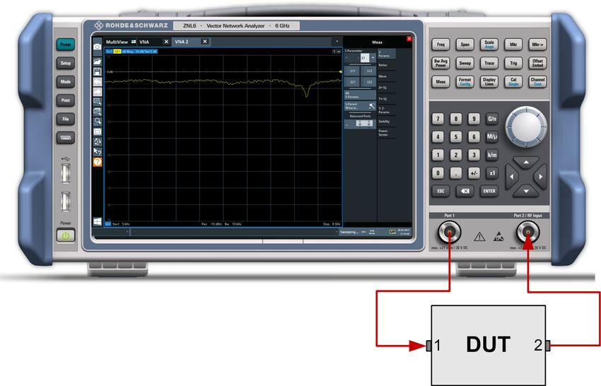
R&S®ZNL                                     Safety and Regulatory Information
                                                                Safety Instructions

1         Safety and Regulatory Information
The product documentation helps you use the product safely and efficiently. Fol-
low the instructions provided here and in the Chapter 1.1, "Safety Instructions",
on page 5.

Intended use
The product is intended for the development, production and verification of elec-
tronic components and devices in industrial, administrative, and laboratory envi-
ronments. Use the product only for its designated purpose. Observe the operating
conditions and performance limits stated in the data sheet.

Where do I find safety information?
Safety information is part of the product documentation. It warns you of potential
dangers and gives instructions on how to prevent personal injury or damage
caused by dangerous situations. Safety information is provided as follows:
● In Chapter 1.1, "Safety Instructions", on page 5. The same information is
  provided in many languages as printed "Safety Instructions". The printed
  "Safety Instructions" are delivered with the product.
● Throughout the documentation, safety instructions are provided when you
  need to take care during setup or operation.

1.1       Safety Instructions
Products from the Rohde & Schwarz group of companies are manufactured
according to the highest technical standards. To use the products safely, follow
the instructions provided here and in the product documentation. Keep the prod-
uct documentation nearby and offer it to other users.
Use the product only for its intended use and within its performance limits. Inten-
ded use and limits are described in the product documentation such as the data
sheet, manuals and the printed safety instructions. If you are unsure about the
appropriate use, contact Rohde & Schwarz customer service.
Using the product requires specialists or specially trained personnel. These users
also need sound knowledge of at least one of the languages in which the user
interfaces and the product documentation are available.

 Getting Started 1323.2867.02 ─ 13                                                5
R&S®ZNL                                      Safety and Regulatory Information
                                                                 Safety Instructions
If any part of the product is damaged or broken, stop using the product. Never
open the casing of the product. Only service personnel authorized by
Rohde & Schwarz are allowed to repair the product. Contact Rohde & Schwarz
customer service at http://www.customersupport.rohde-schwarz.com.

Lifting and carrying the product
The maximum weight of the product is provided in the data sheet. To move the
product safely, you can use lifting or transporting equipment such as lift trucks
and forklifts. Follow the instructions provided by the equipment manufacturer.

Choosing the operating site
Only use the product indoors. The product casing is not waterproof. Water that
enters can electrically connect the casing with live parts, which can lead to elec-
tric shock, serious personal injury or death if you touch the casing. If
Rohde & Schwarz provides a carrying bag designed for your product, you can
use the product outdoors.
Unless otherwise specified, you can operate the product up to an altitude of
2000 m above sea level. The product is suitable for pollution degree 2 environ-
ments where nonconductive contamination can occur. For more information on
environmental conditions such as ambient temperature and humidity, see the
data sheet.

Setting up the product
Always place the product on a stable, flat and level surface with the bottom of the
product facing down. If the product is designed for different positions, secure the
product so that it cannot fall over.
If the product has foldable feet, always fold the feet completely in or out to ensure
stability. The feet can collapse if they are not folded out completely or if the prod-
uct is moved without lifting it. The foldable feet are designed to carry the weight of
the product, but not an extra load.
If stacking is possible, keep in mind that a stack of products can fall over and
cause injury.
If you mount products in a rack, ensure that the rack has sufficient load capacity
and stability. Observe the specifications of the rack manufacturer. Always install
the products from the bottom shelf to the top shelf so that the rack stands
securely. Secure the product so that it cannot fall off the rack.

 Getting Started 1323.2867.02 ─ 13                                                  6
R&S®ZNL                                     Safety and Regulatory Information
                                                               Safety Instructions
Connecting to power
The product is an overvoltage category II product and has to be connected to a
fixed installation used to supply energy-consuming equipment such as household
appliances and similar loads. Be aware that electrically powered products have
risks, such as electric shock, fire, personal injury or even death.
Take the following measures for your safety:
● Before switching on the product, ensure that the voltage and frequency indica-
  ted on the product match the available power source. If the power adapter
  does not adjust automatically, set the correct value and check the rating of the
  fuse.
● If a product has an exchangeable fuse, its type and characteristics are indica-
  ted next to the fuse holder. Before changing the fuse, switch off the instrument
  and disconnect it from the power source. How to change the fuse is described
  in the product documentation.
● Only use the power cable delivered with the product. It complies with country-
  specific safety requirements. Only insert the plug into an outlet with protective
  conductor terminal.
● Only use intact cables and route them carefully so that they cannot be dam-
  aged. Check the power cables regularly to ensure that they are undamaged.
  Also ensure that nobody can trip over loose cables.
● If the product needs an external power supply, use the power supply that is
  delivered with the product or that is recommended in the product documenta-
  tion or a power supply that conforms to the country-specific regulations.
● Only connect the product to a power source with a fuse protection of maxi-
  mum 20 A.
● Ensure that you can disconnect the product from the power source at any
  time. Pull the power plug to disconnect the product. The power plug must be
  easily accessible. If the product is integrated into a system that does not meet
  these requirements, provide an easily accessible circuit breaker at the system
  level.

Cleaning the product
Use a dry, lint-free cloth to clean the product. When cleaning, keep in mind that
the casing is not waterproof. Do not use liquid cleaning agents.

Meaning of safety labels
Safety labels on the product warn against potential hazards.

 Getting Started 1323.2867.02 ─ 13                                                  7
R&S®ZNL                                             Safety and Regulatory Information
                                                                            Safety Instructions

        Potential hazard
        Read the product documentation to avoid personal injury or product damage.

        Electrical hazard
        Indicates live parts. Risk of electric shock, fire, personal injury or even death.

        Hot surface
        Do not touch. Risk of skin burns. Risk of fire.

        Protective conductor terminal
        Connect this terminal to a grounded external conductor or to protective ground. This
        protects you against electric shock should an electric problem occur.

Handling batteries safely
The product contains lithium polymer or lithium ion cells or batteries. The use of
the word battery in the following always means all types. Only the battery con-
tents are potentially hazardous. As long as a battery is undamaged and the seals
remain intact, there is no danger.
Impact, shock or heat can cause damage such as dents, punctures and other
deformations. A damaged battery poses a risk of personal injury. Handle a dam-
aged or leaking battery with extreme care. Immediately ventilate the area since
the battery releases harmful gases. If you come into contact with the battery fluid,
immediately remove all contaminated clothing. Irritation can occur if the battery
fluid comes in contact with your skin or eyes. Immediately and thoroughly rinse
your skin or eyes with water and seek medical aid.
For safe handling, follow these rules:
● Do not short-circuit the battery.
● Do not mechanically damage the battery. Do not open or disassemble the bat-
  tery.
● Do not expose the battery to high temperatures such as open flames, hot sur-
  faces and sunlight.
● Only use the battery with the designated Rohde & Schwarz product.
● Only use the appropriate Rohde & Schwarz charger to charge the batteries. If
  the batteries are improperly charged, there is a risk of explosion. For charging
  and discharging temperature ranges, see the product documentation.
● Store the battery at room temperature (approximately 20 °C) enclosed in the
  original packaging.

 Getting Started 1323.2867.02 ─ 13                                                             8
R&S®ZNL                                           Safety and Regulatory Information
                                                                       Labels on R&S ZNL
● Dispose of batteries separately from normal household waste as specified by
  the local waste disposal agency.
If you disregard these rules, you risk serious personal injury or even death due to
explosion, fire or hazardous chemical substances. The product documentation
provides further details.
When replacing a defective battery, only use the same Rohde & Schwarz battery
type. When returning batteries to Rohde & Schwarz subsidiaries, choose a carrier
qualified to transport dangerous goods and follow the carrier’s transport stipula-
tions in line with IATA-DGR, IMDG-Code, ADR or RID. If you need assistance,
contact the carrier or Rohde & Schwarz customer service.

Connecting headphones
Take the following measures to prevent hearing damage. Before using head-
phones, check the volume and reduce it if necessary. If you monitor varying sig-
nal levels, take off the headphones and wait until the signal has settled. Then
adjust the volume.

1.2       Labels on R&S ZNL
Labels on the casing inform about:
● Personal safety, see "Meaning of safety labels" on page 7
● Product and environment safety, see Table 1-1
● Identification of the product, see Chapter 4.2.14, "Device ID", on page 47
Table 1-1: Labels regarding R&S ZNL and environment safety
       Labeling in line with EN 50419 for disposal of electrical and electronic equipment after
       the product has come to the end of its service life. For more information, see the prod-
       uct user manual, chapter "Disposal".
       Labeling in line with directive 2006/66/EC for disposal of batteries after they have come
       to the end of their service life. For more information, see the R&S ZNL user manual,
       chapter "Disposal".

 Getting Started 1323.2867.02 ─ 13                                                            9
R&S®ZNL                             Safety and Regulatory Information
                                            Korea Certification Class A

1.3     Korea Certification Class A

이 기기는 업무용(A급) 전자파 적합기기로서 판매자 또는 사용자는 이 점을 주의하
시기 바라며, 가정외의 지역에서 사용하는 것을 목적으로 합니다.

Getting Started 1323.2867.02 ─ 13                                   10
R&S®ZNL Documentation Overview
User Manuals and Help
2 Documentation Overview
This section provides an overview of the R&S ZNL user documentation. Unless
specified otherwise, you find the documents on the R&S ZNL product page at:
www.rohde-schwarz.com/manual/ZNL
2.1 Getting Started Manual
Introduces the R&S ZNL and describes how to set up and start working with the
product. Includes basic operations, typical measurement examples, and general
information, e.g. safety instructions, etc.
A printed version is delivered with the instrument. A PDF version is available for
download on the Internet.
2.2 User Manuals and Help
Separate user manuals are provided for the base unit and the firmware applica-
tions:
● Base unit manual
Contains the description of all instrument modes and functions. It also pro-
vides an introduction to remote control, a complete description of the remote
control commands with programming examples, and information on mainte-
nance, instrument interfaces and error messages. Includes the contents of the
getting started manual.
● Firmware application manual
Contains the description of the specific functions of a firmware application,
including remote control commands. Basic information on operating the
R&S ZNL is not included.
The contents of the user manuals are available as help in the R&S ZNL. The help
offers quick, context-sensitive access to the complete information for the base
unit and the firmware applications.
Getting Started 1323.2867.02 ─ 13 11R&S®ZNL Documentation Overview
Data Sheets and Brochures
All user manuals are also available for download or for immediate display on the
Internet.
2.3 Service Manual
Describes the performance test for checking the rated specifications, module
replacement and repair, firmware update, troubleshooting and fault elimination,
and contains mechanical drawings and spare part lists.
The service manual is available for registered users on the global
Rohde & Schwarz information system (GLORIS):
https://gloris.rohde-schwarz.com/irj/portal/SearchDetailView?downloadContai-
nerID=484937
2.4 Instrument Security Procedures
Deals with security issues when working with the R&S ZNL in secure areas. It is
available for download on the Internet.
2.5 Basic Safety Instructions
Contains safety instructions, operating conditions and further important informa-
tion. The printed document is delivered with the instrument.
2.6 Data Sheets and Brochures
The data sheet contains the technical specifications of the R&S ZNL. It also lists
the firmware applications and their order numbers, and optional accessories.
The brochure provides an overview of the instrument and deals with the specific
characteristics.
See www.rohde-schwarz.com/brochure-datasheet/ZNL
Getting Started 1323.2867.02 ─ 13 12R&S®ZNL Documentation Overview
Calibration Certificate
2.7 Release Notes and Open Source Acknowledg-
ment (OSA)
The release notes list new features, improvements and known issues of the cur-
rent firmware version, and describe the firmware installation.
The open-source acknowledgment document provides verbatim license texts of
the used open source software.
See www.rohde-schwarz.com/firmware/ZNL
2.8 Application Notes, Application Cards, White
Papers, etc.
These documents deal with special applications or background information on
particular topics.
See www.rohde-schwarz.com/application/ZNL
2.9 Calibration Certificate
The document is available on https://gloris.rohde-schwarz.com/calcert. You need
the device ID of your instrument, which you can find on a label on the rear panel.
Getting Started 1323.2867.02 ─ 13 13R&S®ZNL Preparing for Use
Unpacking and Checking
3 Preparing for Use
Here, you can find basic information about setting up the instrument for the first
time.
● Lifting and Carrying......................................................................................... 14
● Unpacking and Checking................................................................................ 14
● Choosing the Operating Site........................................................................... 15
● Setting Up the R&S ZNL................................................................................. 15
● Connecting to Power.......................................................................................18
● Switching On or Off......................................................................................... 21
● Connecting to LAN.......................................................................................... 22
● Connecting a Keyboard...................................................................................24
● Connecting an External Monitor......................................................................24
● Windows Operating System............................................................................27
● Logging On......................................................................................................29
● Checking the Supplied Options.......................................................................31
● Considerations for Test Setup......................................................................... 31
3.1 Lifting and Carrying
The carrying handles are designed to lift or carry the instrument. Do not apply
excessive external force to the handles.
See "Lifting and carrying the product" on page 6.
3.2 Unpacking and Checking
1. Unpack the R&S ZNL carefully.
2. Retain the original packing material. Use it when transporting or shipping the
R&S ZNL later.
3. Using the delivery notes, check the equipment for completeness.
Getting Started 1323.2867.02 ─ 13 14R&S®ZNL Preparing for Use
Setting Up the R&S ZNL
4. Check the equipment for damage.
If the delivery is incomplete or equipment is damaged, contact
Rohde & Schwarz.
3.3 Choosing the Operating Site
Specific operating conditions ensure proper operation and avoid damage to the
product and connected devices. For information on environmental conditions
such as ambient temperature and humidity, see the data sheet.
See also "Choosing the operating site" on page 6.
Electromagnetic compatibility classes
The electromagnetic compatibility (EMC) class indicates where you can operate
the product. The EMC class of the product is given in the data sheet under "Gen-
eral data".
● Class B equipment is suitable for use in:
– Residential environments
– Environments that are directly connected to a low-voltage supply network
that supplies residential buildings
● Class A equipment is intended for use in industrial environments. It can cause
radio disturbances in residential environments due to possible conducted and
radiated disturbances. It is therefore not suitable for class B environments.
If class A equipment causes radio disturbances, take appropriate measures to
eliminate them.
3.4 Setting Up the R&S ZNL
The R&S ZNL is designed for use either on a bench top or in a rack, or as a port-
able instrument (with optional battery operation) in a transport bag in the field.
See also:
● "Setting up the product" on page 6
● "Intended use" on page 5
Getting Started 1323.2867.02 ─ 13 15R&S®ZNL Preparing for Use
Setting Up the R&S ZNL
3.4.1 Placing the R&S ZNL on a Bench Top
To place the product on a bench top
1. Place the product on a stable, flat and level surface. Ensure that the surface
can support the weight of the product. For information on the weight, see the
data sheet.
2. CAUTION! Foldable feet can collapse. See "Setting up the product"
on page 6.
Always fold the feet completely in or out. With folded-out feet, do not place
anything on top or underneath.
3. CAUTION! The product can fall over and cause injury. The top surface is too
small for stacking. Never stack another product on top of the product.
As an alternative, you can mount several products in a rack.
4. NOTICE! Overheating can damage the product.
Prevent overheating as follows:
● Keep a minimum distance of 10 cm between the fan openings of the prod-
uct and any object in the vicinity.
● Do not place the product next to heat-generating equipment such as radia-
tors or other products.
3.4.2 Mounting the R&S ZNL in a Rack
To prepare the rack
1. Observe the requirements and instructions in "Setting up the product"
on page 6.
Getting Started 1323.2867.02 ─ 13 16R&S®ZNL Preparing for Use
Setting Up the R&S ZNL
2. NOTICE! Insufficient airflow can cause overheating and damage the product.
Design and implement an efficient ventilation concept for the rack.
To mount the R&S ZNL in a rack
1. Use an adapter kit to prepare the R&S ZNL for rack mounting.
a) Order the rack adapter kit designed for the R&S ZNL. For the order num-
ber, see the data sheet.
b) Mount the adapter kit. Follow the assembly instructions provided with the
adapter kit.
2. Lift the R&S ZNL to shelf height.
3. Grab the handles and push the R&S ZNL onto the shelf until the rack brackets
fit closely to the rack.
4. Tighten all screws in the rack brackets with a tightening torque of 1.2 Nm to
secure the R&S ZNL in the rack.
To unmount the R&S ZNL from a rack
1. Loosen the screws at the rack brackets.
2. Remove the R&S ZNL from the rack.
3. If placing the R&S ZNL on a bench top again, unmount the adapter kit from
the R&S ZNL. Follow the instructions provided with the adapter kit.
3.4.3 Portable Operation
An optional carrying bag designed specifically for the R&S ZNL allows you to pro-
tect the instrument while working in the field. The bag includes ventilation areas at
the position of the ventilation outlets in the casing to ensure air circulation. The
transparent cover allows you to operate the instrument without removing it from
the bag. With the help of the optional vest holster, you can carry the R&S ZNL in
its bag and keep your hands free. Together with the optional battery pack (see
Chapter 3.5.3, "Optional Battery Pack (R&S FPL1-B31)", on page 20), and
packed in the dedicated carrying bag, the R&S ZNL is ideally suited for operation
directly in the field, even in rough environments.
Getting Started 1323.2867.02 ─ 13 17R&S®ZNL Preparing for Use
Connecting to Power
► Inspect the carrying bag for wear and tear before placing the instrument in it.
For details on optional accessories, see the R&S ZNL data sheet.
3.5 Connecting to Power
There are various options to supply power to the R&S ZNL.
● The R&S ZNL is equipped with an AC power supply connector.
● The R&S ZNL can also be equipped with an optional (internal) DC power sup-
ply connector (R&S FPL1-B30).
● The R&S ZNL allows for battery operation if option R&S FPL1-B31 is installed.
3.5.1 Connecting the AC Power
The R&S ZNL can be used with different AC power voltages and adapts itself
automatically to it. Refer to the datasheet for the requirements of voltage and fre-
quency.
For safety information, see "Connecting to power" on page 7.
Getting Started 1323.2867.02 ─ 13 18R&S®ZNL Preparing for Use
Connecting to Power
To connect the AC power
1. Plug the AC power cable into the AC power connector on the rear panel of the
instrument. Only use the AC power cable delivered with the R&S ZNL.
2. Plug the AC power cable into a power outlet with ground contact.
The required ratings are listed next to the AC power connector and in the data
sheet.
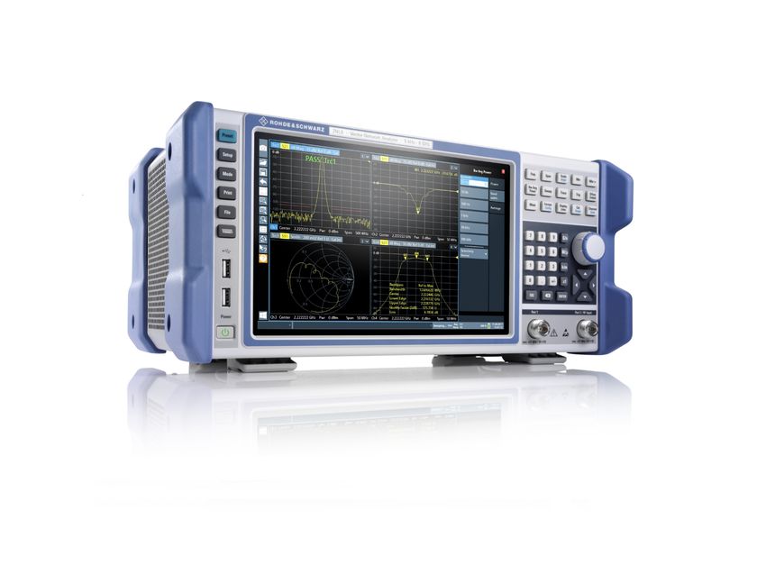
For details on the connector, refer to Chapter 4.2.1, "AC Power Supply Connec-
tion and Main Power Switch", on page 42.
3.5.2 Connecting an Optional DC Power Supply (R&S FPL1-
B30)
The R&S ZNL can also be equipped with an optional DC power supply connector
(R&S FPL1-B30). If installed, the R&S ZNL can be operated by a DC voltage of
+12 V to +24 V. For details on the connector see Chapter 4.2.2, "Li-Ion Battery
Packs and DC Power Connector", on page 43.
If you use an external power supply unit to supply safety extra-low DC voltage
(SELV) to the instrument, be sure to meet the requirements for reinforced/double
insulation in accordance with DIN/EN/IEC 61010 (UL 3111, CSA C22.2 No.
1010.1) or DIN/EN/IEC 60950 (UL 1950, CSA C22.2 No. 950). Provide current
limitation in accordance with DIN EN 61010-1 Appendix F2.1. Use a cable no lon-
ger than 3 m.
Also see "Connecting to power" on page 7.
Getting Started 1323.2867.02 ─ 13 19R&S®ZNL Preparing for Use
Connecting to Power
DC connection
► Connect the DC power connector on the rear panel of the R&S ZNL to the DC
power source using a cable as described above.
3.5.3 Optional Battery Pack (R&S FPL1-B31)
As an alternative to the fixed AC or DC power supply, the R&S ZNL also allows
for battery operation. The "Battery Pack" option R&S FPL1-B31 comprises two Li-
ion batteries and an internal charger. The internal charger charges the batteries
whenever the instrument is connected to AC or DC power. During operation, if
neither DC nor AC power is supplied, the R&S ZNL automatically switches to bat-
tery operation.
The battery pack can be retrofitted by Rohde&Schwarz service.
For models R&S ZNL14 and R&S ZNL20, operation with a single Li-ion bat-
tery is not supported.
For safety information, see "Handling batteries safely" on page 8.
Charging batteries
Charge the batteries before using battery operation for the first time. Following a
long storage period, it can be necessary to charge and discharge the batteries
several times to reach full capacity.
For batteries from third parties, follow the instructions provided by the manufac-
turer. For batteries manufactured by Rohde & Schwarz, observe the following:
● If inserted in the R&S ZNL, batteries are charged via the common AC or DC
power supply.
● You can also use the external battery charger R&S FSV-B34 to charge up to 4
batteries.
● Charge in a temperature range from +0 °C to +45 °C. If the temperature is
above or below these values, or the temparature varies strongly, charging is
Getting Started 1323.2867.02 ─ 13 20R&S®ZNL Preparing for Use
Switching On or Off
interrupted. If the battery temperature rises above +53 °C, charging is stop-
ped.
● Try not to overcharge the battery too often because overcharging reduces the
service life of the battery.
When the battery is being charged in standby mode, the [Power] LED
blinks. During operation, the status bar indicates that the battery is
being charged.
Spare battery pack (R&S FPL1-Z4)
In addition to the internal battery pack (option R&S FPL1-B31), spare batteries
are available for the R&S ZNL. The spare battery pack R&S FPL1-Z4 comprises
two additional Li-ion batteries.
Outside the R&S ZNL, batteries can be charged using the external battery
charger R&S FSV-B34. Even during battery operation, you can exchange the
internal batteries while the R&S ZNL is running, as long as one battery remains in
the instrument. However, it is not recommended to operate the R&S ZNL with
only one battery for a longer period.
For models R&S ZNL14 and R&S ZNL20, operation with a single Li-ion bat-
tery is not supported.
3.6 Switching On or Off
Table 3-1: Overview of power states
Status LED on Power key Position of main power switch
Off gray [0]
Standby orange [I]
Ready green [I]
To switch on the R&S ZNL
The R&S ZNL is off but connected to power.
1. Set the switch on the power supply to position [I].
See Chapter 4.2.1, "AC Power Supply Connection and Main Power Switch",
on page 42.
Getting Started 1323.2867.02 ─ 13 21R&S®ZNL Preparing for Use
Connecting to LAN
The LED of the Power key is orange.
See Chapter 4.1.2, "Power Key", on page 35.
2. Press the Power key.
The LED changes to green.
The instrument operates on battery, DC, or AC power, whichever is supplied.
The R&S ZNL boots.
After booting, the instrument is ready for operation.
To shut down the product
The product is in the ready state.
► Press the [Power] key.
The operating system shuts down. The LED changes to orange.
To disconnect from power
The R&S ZNL is in the standby state.
1. NOTICE! Risk of data loss. If you disconnect the product from power when it
is in the ready state, you can lose settings and data. Shut it down first.
Set the switch on the power supply to position [0].
See Chapter 4.2.1, "AC Power Supply Connection and Main Power Switch",
on page 42.
The LED of the standby key is switched off.
2. Disconnect the R&S ZNL from the power source.
3.7 Connecting to LAN
You can connect the instrument to a LAN for remote operation via a PC.
Provided the network administrator has assigned you the appropriate rights and
adapted the Windows firewall configuration, you can use the interface, for exam-
ple:
● To transfer data between a controlling device and the test device, e.g. to run a
remote control program
● To access or control the measurement from a remote computer using the
"Remote Desktop" application (or a similar tool)
Getting Started 1323.2867.02 ─ 13 22R&S®ZNL Preparing for Use
Connecting to LAN
● To connect external network devices (e.g. printers)
● To transfer data from a remote computer and back, e.g. using network folders
Network environment
Before connecting the product to a local area network (LAN), consider the follow-
ing:
● Install the latest firmware to reduce security risks.
● For internet or remote access, use secured connections, if applicable.
● Ensure that the network settings comply with the security policies of your com-
pany. Contact your local system administrator or IT department before con-
necting your product to your company LAN.
● When connected to the LAN, the product may potentially be accessed from
the internet, which may be a security risk. For example, attackers might mis-
use or damage the product. For more information about IT security and how to
operate the product in a secure LAN environment, see the Rohde & Schwarz
white paper 1EF96: Malware Protection Windows 10.
► NOTICE! Risk of network failure.
Consult your network administrator before performing the following tasks:
● Connecting the instrument to the network
● Configuring the network
● Changing IP addresses
● Exchanging hardware
Errors can affect the entire network.
Connect the R&S ZNL to the LAN via the LAN interface on the rear panel of
the instrument.
Windows automatically detects the network connection and activates the
required drivers.
By default, the R&S ZNL is configured to use DHCP and no static IP address
is configured.
The default instrument name is -, for
example, ZNL3-123456. For information on determining the serial number,
see Chapter 4.2.14, "Device ID", on page 47.
For more information on LAN configuration, see the R&S ZNL user manual.
Getting Started 1323.2867.02 ─ 13 23R&S®ZNL Preparing for Use
Connecting an External Monitor
3.8 Connecting a Keyboard
The keyboard is detected automatically when it is connected. The default input
language is English – US.
However, you can also connect foreign language keyboards; currently the follow-
ing languages are supported for the R&S ZNL:
● German
● Swiss
● French
● Russian
To configure the keyboard language
1. To access the Windows operating system, press the Windows key on the
external keyboard.
2. Select "Start > Settings > Time & language > Region & language > Add a lan-
guage" .
3.9 Connecting an External Monitor
You can connect an external monitor (or projector) to the "DVI" connector on the
rear panel of the R&S ZNL (see also Chapter 4.2.13, "DVI", on page 47).
Getting Started 1323.2867.02 ─ 13 24R&S®ZNL Preparing for Use
Connecting an External Monitor
Screen resolution and format
The touchscreen of the R&S ZNL is calibrated for a 16:10 format. If you con-
nect a monitor or projector using a different format (e.g. 4:3), the calibration
is not correct and the screen does not react to your touch actions properly.
The touchscreen has a screen resolution of 1280x800 pixels. Usually, the
display of the external monitor is a duplicate of the instrument's monitor.
If you configure the external monitor to be used as the only display in the
Windows configuration dialog box ("Show only on 2"), the maximum screen
resolution of the monitor is used. In this case, you can maximize the
R&S ZNL application window and see even more details. You cannot
change the monitor's screen resolution via the standard Windows configura-
tion dialog box.
The R&S ZNL supports a minimum resolution of 1280x768 pixels.
1. Connect the external monitor to the R&S ZNL.
2. Press the [Setup] key.
3. Press the "Display" softkey.
4. Select the "Configure Monitor" tab in the "Display" dialog box.
The standard Windows "Screen Resolution" dialog box is displayed.
Getting Started 1323.2867.02 ─ 13 25R&S®ZNL Preparing for Use
Connecting an External Monitor
5. If necessary, change the screen resolution. Consider the information in the
note above.
6. Select the instrument for display:
● "Display 1" : internal monitor only
● "Display 2" : external monitor only
● "Duplicate" : both internal and external monitor
7. Tap "Apply" to try out the settings before they are accepted permanently, then
you can easily return to the previous settings, if necessary.
8. Select "OK" if the settings are suitable.
Fixing a wrong touchscreen mapping
For instruments that are equipped with a system image version < 0.8, the touch-
screen function is erroneously mapped to the external monitor by default. This
mismatch is particularly inconvenient in extended display mode, where touch ges-
tures on the instrument screen actually operate on the external screen. In dupli-
cate monitor mode, touch screen operation also malfunctions if the resolutions of
the internal and external display do not match.
To fix the mapping between touchscreen and display, connect an external monitor
to the R&S ZNL and proceed as follows:
1. Select [Setup] > "Display" > "Configure Monitor" > "Display Switch" to bring up
the Windows 10 "PROJECT" notification window.
Or press [Win]+[P] on a connected keyboard.
2. Select "Extend".
3. In the Windows task bar, search for "tablet" and select "Tablet PC Settings"
4. In the "Tablet PC Settings" dialog, select "Setup…". Enter the administrator
password to proceed.
Observe the message "Touch this screen to identify it as the touchscreen" on
the internal touch screen.
5. Tap on the internal touch screen.
6. Press [ENTER].
Observe the message "Touch this screen to identify it as the touchscreen" on
the external screen.
7. If the external monitor is also a touchscreen, tap on it.
Getting Started 1323.2867.02 ─ 13 26R&S®ZNL Preparing for Use
Windows Operating System
8. Press [ENTER].
Touch screen operation functions correctly now. Use the "PROJECT" flyout
again to select the appropriate display mode.
Refer to the "Versions + Options" tab of the [Setup] > "System Configura-
tion" dialog to determine the "Image" version of your instrument.
3.10 Windows Operating System
The instrument contains the Windows operating system which has been config-
ured according to the instrument's features and needs. Changes in the system
setup are only required when peripherals like a keyboard or a printer are installed
or if the network configuration does not comply with the default settings. After the
R&S ZNL is started, the operating system boots and the instrument firmware is
started automatically.
Tested software
The drivers and programs used on the instrument under Windows are adapted to
the instrument. Only install update software released by Rohde & Schwarz to
modify existing instrument software.
You can install additional software on the instrument; however, additional soft-
ware can impair instrument function. Thus, run only programs that
Rohde & Schwarz has tested for compatibility with the instrument software.
The following program packages have been tested:
● Symantec Endpoint Security – virus-protection software
● FileShredder - for reliable deletion of files on the hard disk
Service packs and updates
Microsoft regularly creates security updates and other patches to protect Win-
dows-based operating systems. These are released through the Microsoft Update
website and associated update server. Instruments using Windows, especially
those that connect to a network, should be updated regularly.
Getting Started 1323.2867.02 ─ 13 27R&S®ZNL Preparing for Use
Windows Operating System
Firewall settings
A firewall protects an instrument by preventing unauthorized users from gaining
access to it through a network. Rohde & Schwarz highly recommends the use of
the firewall on your instrument. Rohde & Schwarz instruments are shipped with
the Windows firewall enabled and preconfigured in such a way that all ports and
connections for remote control are enabled.
Note that changing firewall settings requires administrator rights.
Virus protection
Take appropriate steps to protect your instruments from infection. Use strong fire-
wall settings and scan any removable storage device used with a
Rohde & Schwarz instrument regularly. It is also recommended that you install
anti-virus software on the instrument. Rohde & Schwarz does NOT recommend
running anti-virus software in the background ("on-access" mode) on Windows-
based instruments, due to potentially degrading instrument performance. How-
ever, Rohde & Schwarz does recommend running it during non-critical hours.
For details and recommendations, see the following Rohde & Schwarz white
paper:
● 1EF96: Malware Protection Windows 10
To access the "Start" menu
The Windows "Start" menu provides access to the Windows functionality and
installed programs.
► Select the "Windows" icon in the toolbar, or press the "Windows" key or the
[CTRL + ESC] key combination on the (external) keyboard.
The "Start" menu and the Windows taskbar are displayed.
The Windows taskbar also provides quick access to commonly used pro-
grams, for example Paint or WordPad. IECWIN, the auxiliary remote control
tool provided free of charge and installed by Rohde & Schwarz, is also avail-
able from the taskbar or "Start" menu.
For details on the IECWIN tool, see the "Network and Remote Control"
chapter of the R&S ZNL user manual.
Getting Started 1323.2867.02 ─ 13 28R&S®ZNL Preparing for Use
Logging On
All necessary system settings can be defined in the "Start > Settings" menu.
For required settings, refer to the Windows documentation and to the hardware
description.
3.11 Logging On
Windows requires that users identify themselves by entering a user name and
password in a login window. By default, the R&S ZNL provides two user
accounts:
● "Instrument": a standard user account with limited access
● "Administrator": an administrator account with unrestricted access to the
computer/domain
Some administrative tasks require administrator rights (e.g. the configuration of a
LAN network). Refer to the description of the basic instrument Setup ([Setup]
menu) to find out which functions are affected.
Passwords
For all default user accounts, the initial password is 894129. Note that this pass-
word is very weak, and it is recommended that you change the password for both
users after initial login. An administrator can change the password in Windows
for any user at any time via "Start > Settings > Account > SignIn Options > Pass-
word > Change".
Auto-login
When shipped, the instrument automatically logs on the default "Instrument" user
to Windows using the default password. This function is active until an adminis-
trator explicitly deactivates it or changes the password.
Changing the password and use of auto-login function
Note that when you change the default password, the default auto-login
function no longer works!
In this case, you must enter the new password manually to log on.
Getting Started 1323.2867.02 ─ 13 29R&S®ZNL Preparing for Use
Logging On
Adapting the auto-login function to a new password
If you change the password that is used during auto-login, this function no longer
works. Adapt the settings for the auto-login function first.
1. Open the
C:\Users\Public\Documents\Rohde-Schwarz\ZNL\user\user\
AUTOLOGIN.REG file in any text editor (e.g. Notepad).
2. In the line "DefaultPassword"="894129", replace the default password
(894129) by the new password for automatic login.
3. Save the changes to the file.
4. In the Windows "Start" menu, select "Run".
The "Run" dialog box is displayed.
5. Enter the command
C:\Users\Public\Documents\Rohde-Schwarz\ZNL\user\user\
AUTOLOGIN.REG.
6. Press the [ENTER] key to confirm.
The auto-login function is reactivated with the changed password. It will be
applied the next time the instrument is switched on.
Switching users when using the auto-login function
Which user account is used is defined during login. If auto-login is active, the
login window is not displayed. However, you can switch the user account to be
used even when the auto-login function is active.
1. Select the "Windows" icon in the toolbar to access the operating system of the
R&S ZNL (see also "To access the "Start" menu" on page 28).
2. Press [CTRL] + [ALT] + [DEL], then select "Sign out".
The "Login" dialog box is displayed, in which you can enter the different user
account name and password.
For information on deactivating and reactivating the auto-login function, see the
R&S ZNL user manual.
Getting Started 1323.2867.02 ─ 13 30R&S®ZNL Preparing for Use
Considerations for Test Setup
3.12 Checking the Supplied Options
The instrument can be equipped with both hardware and firmware options. To
check whether the installed options correspond to the options indicated on the
delivery note, proceed as follows.
1. Press the [SETUP] key.
2. Press the "System Config" softkey.
3. Switch to the "Versions + Options" tab in the "System Configuration" dialog
box.
A list with hardware and firmware information is displayed.
4. Check the availability of the hardware options as indicated in the delivery
note.
3.13 Considerations for Test Setup
Cable selection and electromagnetic interference (EMI)
Electromagnetic interference (EMI) can affect the measurement results.
To suppress electromagnetic radiation during operation:
● Use high-quality shielded cables, for example, double-shielded RF and LAN
cables.
● Always terminate open cable ends.
● Ensure that connected external devices comply with EMC regulations.
Preventing electrostatic discharge (ESD)
Electrostatic discharge is most likely to occur when you connect or disconnect a
DUT.
► NOTICE! Risk of electrostatic discharge. Electrostatic discharge can damage
the electronic components of the product and the device under test (DUT).
Ground yourself to prevent electrostatic discharge damage:
a) Use a wrist strap and cord to connect yourself to ground.
b) Use a conductive floor mat and heel strap combination.
Getting Started 1323.2867.02 ─ 13 31R&S®ZNL Preparing for Use
Considerations for Test Setup
Instrument damage caused by electrostatic discharge
If you are working in an environment where strong ESD discharges are pos-
sible, for additional protection Rohde & Schwarz recommends using broad-
band limiters R&S ZN‑B13 (stock number 1303.7840.02) at each port of
your R&S ZNL3|4|6.
Signal input and output levels
Information on signal levels is provided in the data sheet. Keep the signal levels
within the specified ranges to avoid damage to the R&S ZNL and connected devi-
ces.
Getting Started 1323.2867.02 ─ 13 32R&S®ZNL Instrument Tour
Front Panel View
4 Instrument Tour
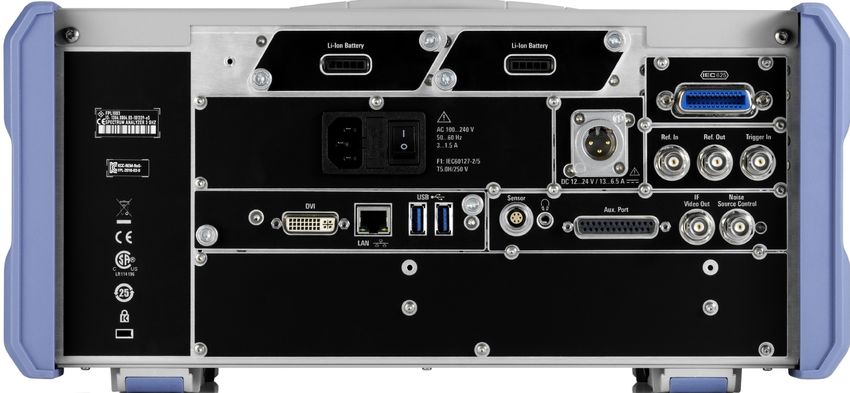
4.1 Front Panel View
This chapter describes the front panel, including all function keys and connectors.
5
3
4
6 7
2
1 8 9
Figure 4-1: Front panel view
1 = Power key
2 = USB (2.0) connectors
3 = System keys
4 = Touchscreen
5 = Function keys
6 = Keypad
7 = Navigation controls
8 = Port 1
9 = Port 2 / RF input 50 Ω connector
4.1.1 Touchscreen
All measurement results are displayed on the screen on the front panel. Addition-
ally, the screen display provides status and setting information and allows you to
switch between various measurement tasks. The screen is touch-sensitive, offer-
ing an alternative means of user interaction for quick and easy handling of the
instrument.
Getting Started 1323.2867.02 ─ 13 33R&S®ZNL Instrument Tour
Front Panel View
1 2 3
4
5
6 7
8
Figure 4-2: Touchscreen elements
1 = Toolbar with standard application functions, e.g. print, save/open file etc.
2 = Tabs for individual channel setups
3 = Softtool panel (a.k.a. softkey bar)
4 = Window title bar with diagram-specific (trace) information
5 = Measurement results (diagram) area
6 = Channel list
7 = Diagram footer with diagram-specific information
8 = Instrument status bar for error messages and date/time display
Using touchscreen gestures, you can perform the following tasks (among others).
(See Chapter 5, "Trying Out the Instrument", on page 49)
● Changing a setting
● Changing the display
● Changing the displayed result range in a diagram
● Moving a marker
● Zooming into a diagram
● Selecting a new evaluation method
Getting Started 1323.2867.02 ─ 13 34R&S®ZNL Instrument Tour
Front Panel View
● Scrolling through a result list or table
● Saving or printing results and settings
To imitate a right-click by mouse using the touchscreen, for example to open a
context-sensitive menu for a specific item, press the screen for about 1 second.
For details on touchscreen gestures, see Chapter 6.4, "Touchscreen Gestures",
on page 85.
4.1.2 Power Key
The [Power] key is located on the lower left corner of the front panel. It starts up
and shuts down the instrument.
See also "Connecting to power" on page 7 and Chapter 3.5, "Connecting to
Power", on page 18.
4.1.3 USB
The front panel provides two female USB connectors (USB-A, 2.0 standard) to
connect devices like a keyboard or a mouse. A memory stick can be connected to
store and reload instrument settings and measurement data.
The rear panel provides further USB connectors (standard 3.0), see Chap-
ter 4.2.11, "USB", on page 47.
4.1.4 System Keys
System keys set the instrument to a predefined state, change basic settings, and
provide print and display functions.
A detailed description of the corresponding functions is provided in the R&S ZNL
user manual.
Getting Started 1323.2867.02 ─ 13 35R&S®ZNL Instrument Tour
Front Panel View
Table 4-1: System keys
System key Assigned functions
[Preset] Resets the instrument to the default state.
[Setup] Provides basic instrument configuration functions, e.g.:
● Reference frequency (external/internal)
● Date, time, display configuration
● LAN interface
● Firmware update and enabling of options
● Information about instrument configuration incl. firmware ver-
sion and system error messages
● Service support functions (self-test etc.)
● Self-alignment (with spectrum analysis option)
[Mode] Manages channel setups
[Print] Provides configuration settings for the print function
[FILE] Provides save/recall functions for instrument settings and mea-
surement results
Switches between the on-screen keyboard display:
● At the top of the screen
● At the bottom of the screen
● Off
4.1.5 Function Keys
Function keys provide access to the most common measurement settings and
functions.
A detailed description of the corresponding functions is provided in the R&S ZNL
user manual.
The labels indicated in italics (blue font color on the instrument) apply to the
optional Spectrum mode only.
Getting Started 1323.2867.02 ─ 13 36R&S®ZNL Instrument Tour
Front Panel View
Table 4-2: Function keys
Function key Assigned functions
VNA mode SA mode
[Freq] Defines the sweep range. Sets the center frequency and the
start and stop frequencies for the
frequency range under considera-
tion. This key is also used to set the
frequency offset and the signal track
function.
[Span] Sets the frequency span to be ana-
lyzed
[Scale] Defines the scaling and zooming of Sets the reference level, the dis-
[Ampt] diagrams. played dynamic range, the RF
attenuation and the unit for the level
display
Sets the level offset and the input
impedance
[Mkr] Defines and positions absolute and relative measurement markers (markers
and delta markers).
Selects special marker functions
[Mkr->] Used for search functions of the measurement markers (maximum/minimum
of the trace).
Assigns the marker frequency to the center frequency, and the marker level
to the reference level.
Restricts the search area (Search Limits) and characterizes the maximum
points and minimum points (Peak Excursion).
[Bw Avg Power] Defines the power of the internal sig- Sets the resolution bandwidth and
nal sources, selects the (optional) the video bandwidth.
receiver step attenuators and the IF
bandwidths, and sets up averaging.
[Sweep] Defines the sweep type and other Sets the sweep time and the number
sweep parameters; controls sweep of measurement points
execution. Selects continuous measurement or
single measurement
[Trace] Configures the graphical analysis of measurement results.
[Trig] Defines how measurement sweeps Sets the trigger mode, the trigger
are triggered. threshold, the trigger delay, and the
gate configuration for gated sweep
[Offset Embed] Contains functions for deembedding/ Performs a peak search for active
embedding the DUT from/into physi- marker. If no marker is active, nor-
cal/virtual (matching) networks placed mal marker 1 is activated and the
between the calibrated reference peak search is performed for it.
plane and the DUT.
Getting Started 1323.2867.02 ─ 13 37R&S®ZNL Instrument Tour
Front Panel View
Function key Assigned functions
VNA mode SA mode
[Meas] Selects the quantities to be measured and displayed.
[Format] Selects the trace format (dB magni- Configure measurements and data
[Config] tude, Smith, etc.). input and output
[Display Lines] Configures display lines and limit lines.
[Cal] Provides all functions related to sys- Starts and stops a single new mea-
[Single] tem error calibration. surement (Single Sweep Mode)
[Channel] Creates and deletes channel setups Starts and stops a continuous mea-
[Cont] and optimize the measurement proc- surement (Continuous Sweep Mode)
ess.
4.1.6 Keypad
The keypad is used to enter numeric parameters, including the corresponding
units. It contains the following keys:
Table 4-3: Keys on the keypad
Type of key Description
Decimal point Inserts a decimal point "." at the cursor position.
Sign key Changes the sign of a numeric parameter. For alphanumeric
parameters, inserts a "-" at the cursor position.
Unit keys Adds the selected unit to the entered numeric value and com-
(G/n, M/μ, k/m, x1) plete the entry.
For level entries (e.g. in dB) or dimensionless values, all units
have the value "1" as multiplying factor. Thus, they have the
same function as an [ENTER] key.
[ESC] Closes all kinds of dialog boxes, if the edit mode is not active.
Quits the edit mode, if the edit mode is active. In dialog boxes
that contain a "Cancel" button it activates that button.
For "Edit" dialog boxes the following mechanism is used:
● If data entry has been started, it retains the original value
and closes the dialog box.
● If data entry has not been started or has been completed, it
closes the dialog box.
Getting Started 1323.2867.02 ─ 13 38You can also read