Residual Stress and Microstructure of a Ti-6Al-4V Wire Arc Additive Manufacturing Hybrid Demonstrator
←
→
Page content transcription
If your browser does not render page correctly, please read the page content below
Article

Residual Stress and Microstructure of a Ti-6Al-4V
Wire Arc Additive Manufacturing Hybrid
Demonstrator
Tatiana Mishurova 1,*, Benjamin Sydow 2, Tobias Thiede 1, Irina Sizova 2, Alexander Ulbricht 1,
Markus Bambach 2,3 and Giovanni Bruno 1,4
 1 Bundesanstalt für Materialforschung und–prüfung (Institute for Materials Research and Testing (BAM),
 12205 Berlin, Germany; tobias.thiede@bam.de (T.T.); Alexander.Ulbricht@bam.de (A.U.);
 giovanni.bruno@bam.de (G.B.)
 2 Chair of Mechanical Design and Manufacturing, Brandenburg University of Technology Cottbus-

 Senftenberg, D-03046 Cottbus, Germany; benjamin.sydow@b-tu.de (B.S.); sizova@b-tu.de (I.S.);
 bambach@b-tu.de (M.B.)
 3 Advanced Manufacturing, Department of Mechanical and Process Engineering, ETH Zurich,

 8092 Zurich, Switzerland
 4 Institute of Physics and Astronomy, University of Potsdam, 14476 Potsdam, Germany

 * Correspondence: tatiana.mishurova@bam.de; Tel.: +49-30-810-445-27

 Received: 9 April 2020; Accepted: 23 May 2020; Published: 26 May 2020

 Abstract: Wire Arc Additive Manufacturing (WAAM) features high deposition rates and, thus,
 allows production of large components that are relevant for aerospace applications. However, a lot
 of aerospace parts are currently produced by forging or machining alone to ensure fast production
 and to obtain good mechanical properties; the use of these conventional process routes causes high
 tooling and material costs. A hybrid approach (a combination of forging and WAAM) allows
 making production more efficient. In this fashion, further structural or functional features can be
 built in any direction without using additional tools for every part. By using a combination of
 forging basic geometries with one tool set and adding the functional features by means of WAAM,
 the tool costs and material waste can be reduced compared to either completely forged or machined
 parts. One of the factors influencing the structural integrity of additively manufactured parts are
 (high) residual stresses, generated during the build process. In this study, the triaxial residual stress
 profiles in a hybrid WAAM part are reported, as determined by neutron diffraction. The analysis is
 complemented by microstructural investigations, showing a gradient of microstructure (shape and
 size of grains) along the part height. The highest residual stresses were found in the transition zone
 (between WAAM and forged part). The total stress range showed to be lower than expected for
 WAAM components. This could be explained by the thermal history of the component.

 Keywords: residual stress; WAAM; Ti-6Al-4V; additive manufacturing; neutron diffraction; hybrid
 manufacturing

1. Introduction
 The titanium alloy Ti-6Al-4V is intensively used in lightweight applications for the aviation and
space industry because of its high specific strength [1]. Hot forging is the usual manufacturing route;
this allows better material formation and control of the microstructure. Subsequent machining is used
to attain the desired tolerances regarding dimensions, shape, and surface condition [2]. One positive
effect of hot forging is that the microstructure and the fiber flow can be optimized, which results in

Metals 2020, 10, 701; doi:10.3390/met10060701 www.mdpi.com/journal/metals
Metals 2020, 10, 701 2 of 15

excellent mechanical properties. However, forging is limited as far as the achievable geometries is
concerned: as an example, due to friction and heat transfer, the material cannot flow into cavities of
the forging die with a large depth-to-diameter ratio. Moreover, multistage hot forging operations
require expensive heated die sets and lead to parts with large tolerances; this requires further
machining to create the final shape. In fact, the “buy-to-fly” ratio (the mass ratio between the
originally purchased stock material used to produce a part and the mass of the final finished part)
ranges from 12:1 to 25:1 for aircraft titanium components made by traditional manufacturing
techniques [3]. This means that 12–25 kg of raw material are required to produce just 1 kg of parts. In
this way, more than 90% of the material is machined away. Such a high buy-to-fly ratio is
unacceptable from many points of view. For a typical titanium component produced by additive
manufacturing (AM) techniques the buy-to-fly ratio drops to 3–12:1 [4] and can even be close to 1:1
[5]. By using AM for production of aerospace components not only costs for expensive titanium alloys
can be reduced, but also the machining time can be drastically cut.
 AM is an innovative manufacturing technology that allows manufacturing almost arbitrarily
complex shapes. In powder-bed metal AM processes, the powder is distributed layer-wise on a
substrate or already deposited material and fused by melting the material using an electron (electron
beam melting–EB-PBF) or laser beam (laser powder bed fusion–L-PBF). Because of the small
(focused) beam, the deposition rates are quite low. PBF AM processes have in general a small layer
thickness of a few tens of μm up to 2 mm [6]. This is necessary due to the local bonding of adjacent
powder particles and the limited beam penetration depth. Although beam scanning systems can
achieve high laser or electron beam scanning speeds, large parts require a high number of layers,
which causes high production times. The part size is limited due to the small process chamber
(typically 200–300 mm edge size). Also, as the powder-bed has to be established before the AM
process begins, no existing parts can be extended by means of PBF. This makes this technology only
attractive for small parts. An increasingly popular AM technology that may allow overcoming this
issue is Wire Arc Additive Manufacturing (WAAM). WAAM utilizes common and well-known
welding technologies. A wire is fed to the desired position and molten by an electric arc. The melt
pool solidifies and forms a weld bead. One advantage of WAAM compared to other AM technologies
is the high deposition rate. This is especially important for large scale products such as landing gear
parts or wing ribs, which are difficult to forge due to their size or have a large material waste when
machined. WAAM achieves deposition rates as high as several kg/h [7] Also, a wide range of
materials is available as wires, which offers multiple possible applications. The microstructure and
mechanical performance of WAAM manufactured Ti-6Al-4V parts will not reach the level of forged
material without additional (often expensive) post-processing techniques such as hot isostatic
pressing (HIP) or thermomechanical processing [8]. One strategy is to combine the benefits of the two
technologies (forging and WAAM) to produce so-called hybrid parts with the desired mechanical
properties (even at local scale). This approach is of particular interest for the production of the
components, where the forged sections are heavily loaded during service and the added AM features
should be capable to withstand only moderate loads. Moreover, in aerospace industry many parts
possess a symmetry axis. To produce such components by means of conventional processing a
number of different forging die sets should be used. Instead, the hybrid approach can be more
efficient, since the required structural or functional features can be added to the forged part without
using additional tools for every part design. In so doing, both the cost of forging tools and material
waste can be reduced. Figure 1 represents a possible hybrid manufacturing route, where the basic
structure can be produced by hot forming and the missed structural features can be added using AM.
 Basically, two process routes are possible: (i) AM and subsequent forming or (ii) forming and
subsequent AM. The first hybrid processing route was extensively studied by authors of the present
work in regard to Ti-6Al-4V [9–11]. It was observed that Ti-6Al-4V pre-forms for forging made either
by L-PBF or by WAAM show a good hot workability. Moreover, voids could be closed applying
compressive stresses at elevated temperature, so that the final microstructure and mechanical
properties could be improved. Extensive work on the second hybrid processing route can also be
found in the literature.
Metals 2020, 10, 701 3 of 15

 Figure 1. Illustration of the possible hybrid manufacturing route combining metal hot forming and
 WAAM.

 Bambach et al. [11] examined the same demonstrator shape and process route (forging with
subsequent WAAM) used in this study and proved that its mechanical properties exceeded the
minimum requirements for forged parts regarding yield strength (YS = 837 MPa > 830 MPa) and
ultimate tensile strength (UTS = 934 MPa > 900 MPa). Also, only minor anisotropic behavior was
observed. In another work, Bambach et al. [12] showed that laser cladding technology could be used
to produce flexibly applicable local patches to locally increase the stiffness or the thickness of sheet
metal components. Papke et al. [13] analyzed tensile bonding strength of hybrid parts made of Ti-
6Al-4V produced by combination of laser beam melting and warm bending. It was reported, that
sheet material and AM material possess different hardness values, and the sheet thickness strongly
influences the bonding strength. Moreover, it was confirmed, that the contact zone between sheet
and AM is the most significant for the strength of hybrid components [14]. Hirtler et al. [15]
investigated the production of modifying stiffening ribs made of AlSi12 on conventionally produced
pre-forms (EN-AW 6082). The authors proved the feasibility of the process combination between
WAAM and hot forming. In general, most of the existing work on hybrid manufactured of Ti-6Al-4V
concentrates on the increase of the strength of the sheet metal components using AM.
 To produce a sound Ti-6Al-4V hybrid part the microstructure should be thoroughly controlled.
During WAAM of Ti-6Al-4V β-grains (BCC) grow epitaxially, similar to PBF AM techniques [16].
Such microstructures are hard to avoid because at the low concentration Al and V have a high
solubility in the alloy and, thus, do not partition ahead of the solidification front [17]. The length of
prior β grains along the solidification direction can reach a few cm or even cover the whole height of
the sample, possessing a strong fiber texture [18]. After cooling below the β-transus
temperature (approximately 995 ± 25 °C) β grains typically transform to fine α laths (HCP) retaining
β lamellar structure (Widmanstätten structure). Here the thickness of α-platelets and the sizes of β-
grains are the fundamental parameters that affect the mechanical performance of Ti-6Al-4V alloy.
Very high cooling rates (>410 °C/s) promote martensitic transformation. Slower cooling rates (
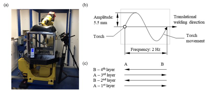
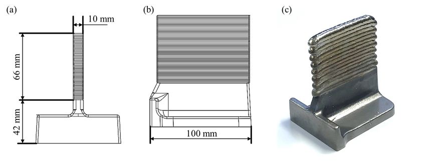
Metals 2020, 10, 701 4 of 15

for Ti-6Al-4V AM parts. The connection between microstructure and RS for welded and AM
materials has been reported in several studies [29–32]. Due to high cooling rate needed for martensitic
transformation (β→α´) in Ti-6Al-4V, the martensitic microstructure is often linked with high tensile
RS [30]. It has been shown that the presence of β phase in PBF Ti-6Al-4V, introduced by intrinsic heat
treatment, leads to the RS relaxation [31]. Thus, for the general application of WAAM, it is important
to understand the microstructure and the RS in as-manufactured WAAM components. Such
properties depend also on the location in the hybrid part. An investigation of the microstructure and
the RS at the interface between forged and AM features is here of particular importance. In AM parts,
high tensile RS is usually reached at the interface between the substrate and the deposited material
[33]. This could be critical for the utilization of hybrid parts.
 The main aim of the current study is to investigate the microstructure and the RS distribution in
a hybrid part produced by the combination of conventional hot forming and WAAM. A T-section
geometry manufactured by means of WAAM on a hot forging pre-form is investigated. The paper is
structured as follows: Section 2 presents the manufacturing of hybrid Ti-6Al-4V parts using WAAM
and hot forging. Also, the procedures of microstructural analysis and of determination of RS by
means of neutron diffraction are presented. Section 3 gives an overview of results of metallographic
examinations and RS. Finally, the results are discussed, and conclusions are presented.

2. Materials and Methods

2.1. Sample Manufacturing
 The considered hybrid process route encompassed forging and subsequent WAAM of Ti-6Al-
4V. A T-shaped pre-form was forged, as shown in Figure 2. It contained a 10 mm wide and ~90 mm
long rib, which was milled flat at a total height of 42 mm. The WAAM process was used to increase
the height of the rib by 66 mm.
 Hot forging was performed in the α + β-temperature range using a 2500 t crank press at OTTO
FUCHS KG (Meinerzhagen, Germany). The forged part was machined on the top side to obtain a flat
surface to ensure a stable WAAM process.

 Figure 2. Drawing of the final pre-form with dimensions. Front view (a), side view (b), final
 appearance of the hybrid near-net shape demonstrator (c).

 WAAM was performed using a Fanuc six-axis robot (FANUC Europe Corporation S. A.,
Echternach, Luxembourg) and a TPS 500i welding power source (Fronius®, Wels, Austria) utilizing
the Cold Metal Transfer (CMT) variant of the Gas Metal Arc Welding (GMAW) process. The welding
was carried out in an argon filled, sealed chamber to avoid oxidation. The chamber was equipped
with an O2 sensor. Pre-heating of the sample was not applied. The used WAAM set-up is displayed
in Figure 3a. A Ti-6Al-4V wire with a diameter of 1.0 mm was used. One hybrid demonstrator was
produced for investigations. The shielding gas flow rate at the torch was 15 L/min, also the build
Metals 2020, 10, 701 5 of 15

chamber was flooded with 50 L/min before the deposition process. During deposition the chamber
gas flow rate was reduced to 20 L/min to compensate the small gas leakage. The argon gas purity was
≥ 99.99%. The chemical composition for as-built Ti-6Al-4V WAAM is shown in Table 1.

 Table 1. Chemical composition of Ti-6Al-4V as-built by WAAM (max. weight %).

 Ti Al V Fe C Other
 Bal. 6.45 3.87 0.19 0.07 0.17

 The deposition pattern is shown in Figure 3b,c. The starting point (A/B) changed for every layer
using a bidirectional tool path on a single bead. A sinus wave was superposed onto the translational
motion of the torch to obtain the desired wall thickness. The layer thickness was approximately 4.4
mm. The number of deposited layers was 15.

 Figure 3. For the WAAM process (a) used WAAM machine, (b) applied sinus wave movement and
 (c) swapping of the starting point each layer.

 The welding parameters are shown in Table 2. The first three layers were welded with a higher
electrical current to achieve a good fusion with the forged substrate and to increase the average
temperature (this ensures a stable WAAM process). The current was than reduced to 100 A for the
following layers.

 Table 2. WAAM manufacturing parameters.

 Parameter Value
 Wire diameter 1.0 mm
 Amplitude 5.5 mm
 Frequency 2 Hz
 Welding speed 15 cm/min
 Cooling time between deposition of each layer 130 s
 Average electrical voltage 13.5 V
 1st layer: 135 A
 2nd layer: 115 A
 Average electrical current
 3rd layer: 105 A
 ≥4th layers: 100 A

2.2. Microstructural Characterization
 In order to investigate the microstructure, the manufactured hybrid part (including the forged
region) was cut along the build direction. The sample was mounted with the cut cross-sections on
top and ground flat with successively finer grades (from 320 to 1200 μm) of silicon carbide (SiC)
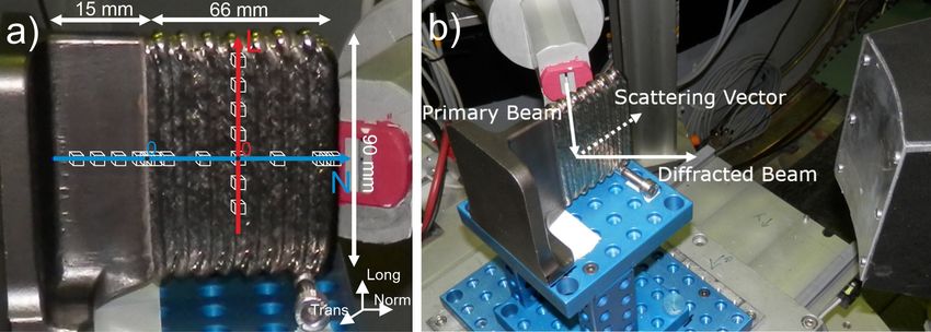
Metals 2020, 10, 701 6 of 15

papers. The specimen was then polished with 0.05 μm silica solution (OP-S Suspension, Struers
GmbH, Willich, Germany) with the addition of H2O2, HNO3, and HF. Sample was etched with Kroll’s
agent solution to reveal the microstructure. The sections were analyzed using an optical microscope
Carl Zeiss Axiotech by Carl Zeiss Microscopy (Jena, Germany).

2.3. Residual Stress Analysis
 The neutron diffraction experiment was conducted on the instrument E3 at BER II reactor
(Helmholtz Zentrum Berlin, Germany) [34]. A monochromatic neutron beam of wavelength λ = 1.476
Å was used. The three orthogonal strain components, assumed to be principal directions based on
the sample geometry, were measured (longitudinal, transversal, normal, see Figure 4). The
longitudinal and normal directions coincided with the deposition and the build direction of WAAM,
respectively. The acquisition time was set to 75 min for each stress component. Additionally, to
improve the diffraction signal, a constant ω oscillation of ±10° around the scattering vector (this is the
bisectrix between the incident and the diffracted beam directions and corresponds to the direction in
which the strain is measured) was performed. For the longitudinal stress component, a primary slit
with opening of 4 mm × 4 mm was used. For the normal and transversal component, a primary slit
with vertical opening of 18 mm and horizontal opening of 2 mm was used. This allowed at the same
time increasing the signal and keeping high spatial resolution along the build direction of the sample.
A secondary collimator with a focus of 2 mm was used for all measurements. The strain was
measured along two lines: along the deposition direction at the middle height of the WAAM part (L-
line) and along the build direction (N-line). The measured points and coordinate system are
schematically presented in Figure 4a.

 Figure 4. Photo of sample during neutron diffraction experiment on E3 with the schematics of (a) the
 measured points and the coordinate system, (b) the set-up. (Note that the sample is aligned for the
 measurement on the normal strain component).

 The measurements were performed at the diffraction angle 2 = 76°, which allowed the
simultaneous detections of three diffraction peaks for α-Ti: 1122, 2021and 0004. However, only the
1122-α reflection appeared at every measured point and sample direction, therefore the RS was
calculated for this crystallographic family. The lattice spacing d was calculated according to Bragg’s
law:

 = (1)
 2 ∙
 The lattice spacing (averaged within the gauge volume) was determined by fitting the diffraction
peak with a Gaussian function using the software StressTexCalculator 1.53 (TU-Clausthal, Germany).
In order to calculate lattice strains ε a strain-free reference d0 has to be used, since:
 −
 = = −1 (2)
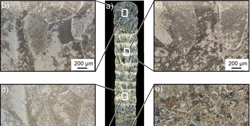
Metals 2020, 10, 701 7 of 15

 One of the main problems in diffraction-based RS analysis is the estimation of such a reference
[35,36]. There are different approaches for the determination of d0: measurements using a reference
powder or stress-relieved coupons; or calculations using a global average or stress balance/boundary
conditions.In the case of AM materials the variation of the microstructure inside the part and the
different thermal history of the part from the raw material (power, wire) makes the determination of
d0 even more challenging [35]. In our case, a global d0 (or θ0) was taken as the average of all measured
points, as proposed in [37]. This value was 2θ0 = 72.856° with an average error of ±0.007° (coming
from the fit of all diffraction peaks). As an alternative, the stress balance condition was applied to the
L-line scan for the normal component (Figure 4): = 0. For this estimation the stress profile
was extrapolated to the surface and interpolated between the points with a B-spline function.
Symmetry of the stress profile was assumed, i.e., (+ ) = (− ) . Using this approach, we
obtained 2 = 72.859°. This value lies within the error range of the 2θ0 obtained using the global
average approach and shifts the resulting stress values only by +10 MPa. Therefore, only stress
profiles calculated satisfying the above-mentioned stress balance conditions will be reported.
 RS were calculated according to the tensorial Hooke’s Law: = , with C as the stiffness tensor.
With the assumption that the principal geometric directions are also principal stress directions,
Hooke’s Law in the case of a quasi-isotropic solid reads:

 , , = 1− , , + , , + , , (3)
 1+ 1 − 2
where , , and , , are stresses and strains along the longitudinal, transversal and normal
direction, and = 112.7 GPa and = 0.321 are the diffraction elastic constants for α-Ti 1122
reflection calculated by the Kröner’s model [38].
 Hydrostatic stress and von Mises stresses were calculated according to:

 + +
 = (4)
 3

 1
 = ( − ) + ( − ) + ( − ) (5)
 2

3. Results and Discussion
 Figure 5 and Figure 6 show the macro- and microstructure of the hybrid part, respectively. To
interpret the microstructural features, we must recall that the first layers were produced with higher
current (see Table 2) to compensate the heat sink effect of the substrate. Then, the heat input (i.e.,
current) was gradually decreased, and after the fourth layer it was set to a constant value. The
macrostructure of the WAAM Ti-6Al-4V is characterized by the epitaxial growth of large columnar
prior β-grains, which stretch through several deposited layers (Figure 5). The average dimensions of
such grains are about 1.3 mm perpendicular and 8 mm parallel to the build direction.
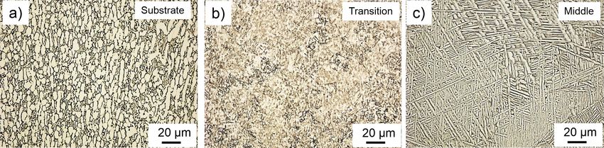
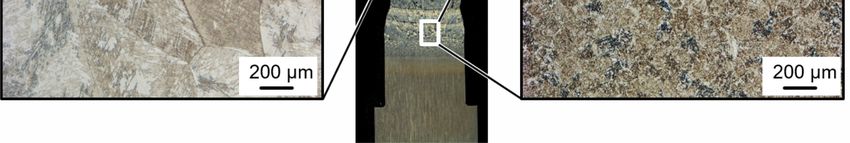
Metals 2020, 10, 701 8 of 15

 Figure 5. (a) Micrograph showing prior β-Ti grains in the middle section of the sample with enlarged
 view for (b) top of WAAM part, (c) and (d) middle height of WAAM part, (e) transition region
 between WAAM and forged parts.

 The forged Ti-6Al-4V T-section shows, instead, a bi-modal α+β microstructure (Figure 6a),
typically obtained in Ti-6Al-4V after conventional thermomechanical processing [21]. The first layers
of the WAAM material are characterized by a higher cooling rate compared to the following layers,
due to heat conduction to the substrate. Therefore, in the transition zone (e.g., in the first layers, up
to approximately 7 mm distance from the seam line), a fine martensitic α’ microstructure is found
within small globular prior β-grains with average dimensions of approximately 50 μm (Figure 6b).

 Figure 6. Typical micrographs obtained (a) in the substrate, (b) in the transition zone close to the
 substrate, (c) in the center of the WAAM part.

 At sample mid-height, the micrographs show an αw-Widmanstätten microstructure with a
thickness of the α-platelets of approximately 2 μm within the columnar prior β-grains (Figure 6c).
Such microstructures are often reported in the literature [3]. Moreover, the α-phase also appears as a
thin layer on the prior β-grain boundaries with a thickness comparable to the thickness of the α-
platelets. This microstructure was generated by the repeated rapid heating and cooling that occur
during the WAAM process. It is important to stress that the coarse prior β grains may critically affect
the mechanical properties (since β is more ductile than α).
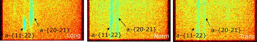
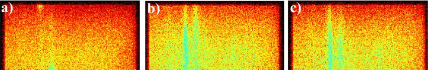
Metals 2020, 10, 701 9 of 15

 A flat panel detector was used in the neutron diffraction experiment. The 2D distributions of the
diffraction signal give valuable information about the microstructure (Figure 7): especially in the
longitudinal direction, diffraction spots (instead of the typical Debye rings observed for
polycrystalline materials) were observed. This is called the “coarse grain effect” (Figure 7a). The grain
size of α-Ti laths is quite small, with an average thickness of about 2 μm and an average length of
about 25 μm (see Figure 6). However, the origin of α-Ti laths create a distinct crystallographic texture.
All the grains of α-Ti inside the prior β-grain are only variants of the same crystallographic
orientation, according to Burgers orientation relation [39]. Thus, from the crystallographic point of
view, such laths form coarse grains, which scatter similarly to single crystals in the longitudinal
direction. In spite of this effect, the projections of the few spots inside a 2D detector image could be
analyzed as a Bragg peak, and the lattice parameter could be reliably determined.

 Figure 7. Image of 2D detector obtained during neutron diffraction experiment on the WAAM part
 (at 46 mm) for (a) longitudinal direction, (b) normal direction, (c) transversal direction. Note: the
 images are normalized to the maximum intensity, the pixel size is 1.17 mm × 1.17 mm.

 The neutron diffraction patterns (i.e. integrated along the Debye ring) collected along the L-line
for three orthogonal directions are presented in Figure 8. The patterns look similar at every position,
thereby showing no microstructural variations along the deposition direction. The peak intensities
(of both 1122 and 2021 reflections) do not vary for different orientations, highlighting the absence
of a strong crystallographic texture.

 Figure 8. Diffraction patterns along the L-line for (a) transversal component, (b) normal component,
 (c) longitudinal component.

 The intensity ratios follow the theoretical predictions for the neutron diffraction pattern of HCP-
Ti powder (i.e., assuming random crystallographic texture, calculated by PowderCell [40]): the
Metals 2020, 10, 701 10 of 15

intensity of the 1122 reflection is the highest out of the three reflections observed, followed by 2021
and 0004 reflection.
 In contrast to the diffraction patterns acquired along the deposition direction (L-line, Figure 8),
a decrease of the intensity towards the substrate for all reflections of the transversal strain component
can be observed along the build direction (Figure 9a). As shown in Figure 2, the thickness of the
sample is the same as the thickness of the substrate (in the analyzed region up to 15 mm of substrate),
so this cannot be caused by higher neutron absorption. In other words, the path of the neutron beam
stays the same for the WAAM and the forged part. Therefore, this intensity variation is an evidence
of the microstructural changes reported in Figure 6 and, in particular, of the crystallographic texture.
The ratio between the 1122 and 2021 peak intensities changes with the height for the longitudinal
component (Figure 9c). The 0004 peak increases its intensity for the points in the transition zone and
inside the substrate for the normal component (Figure 9b). Thus, an increase in intensity from the
prismatic crystallographic plane (1000) for the transversal component could be expected. Since we
mostly observed mixed reflections (1122 and 2021), it is hard (and anyway out of the scope of this
study) to quantify the effect of crystallographic texture from the current experiments.

 Figure 9. Diffractograms along the N-line for (a) transversal component, (b) normal component, (c)
 longitudinal component.

 The normalized integrated intensity and the full width at half maximum (FWHM) of diffraction
peaks along the N-line are presented in Figure 10. Although the coarse grain effect was observed for
the longitudinal component (Figure 7a), the FWHM and the integrated intensity of the peak did not
vary within the sample (Figure 10b). As for the transition zone and for the substrate, the intensity
drops for each measured strain component. In the substrate (Figure 6a), the intensity increases for
the normal component. This can be caused by microstructural and crystallographic texture changes
(see Figure 5 and Figure 6). It should be noticed that most changes happen in the transition region
(from +10 mm to −10 mm) and stabilize inside the WAAM section and the substrate. An increase of
the FWHM is often connected to plastic deformation of the material, however, in the present case the
FWHM remains constant for the whole height of the sample. Only the transversal component of some
points in the substrate shows an increase of the FWHM; this is an artifact due to the low intensity of
the peaks (i.e., higher fitting error), see Figure 9a.
Metals 2020, 10, 701 11 of 15

 Figure 10. (a) FWHM and (b) normalized integrated intensity of the 1122-Ti diffraction peak along
 the build direction.

 The hydrostatic and von Mises stress profiles along L- and N-lines are presented in
Figure 11. The stress range for both is around 100 MPa. The hydrostatic stresses cannot be released
by post-processing heat treatment and, hence, could be critical for structural integrity of the part
under load. In the present case, reaches its maximum value of around 75 MPa, this is only 10%
of the yield stress of WAAM Ti-6Al-4V (around 750 MPa according to [41]). While this value is not
critical for the part integrity, it should be taken into account when assessing the life of the component
(e.g. under fatigue).

 Figure 11. Hydrostatic and von Mises stress along (a) L-line, (b) N-line. Error bars are contained in
 the markers.

 The longitudinal RS profile along the sample L-line shows a maximum (about 100 MPa) in the
middle of the sample (Figure 12a). The profile is symmetric and is similar to that simulated by Ding
et al [42] for steel WAAM parts. The stress profiles along N-line are more complicated (Figure 12b).
In the literature the longitudinal component of the RS (coinciding with the deposition direction)
usually shows the highest values and the highest gradients. Several experimental RS determination
methods (such as the contour method [43] and neutron diffraction [44]) and modeling [42] have
revealed the typical longitudinal RS profile generated along the height of WAAM parts. There is some
consensus that high tensile stress appears in the region near the substrate and constantly decreases
to compressive towards the top of the sample (see schematic in Figure 12c). This is also typical for
stress profiles across heterogeneous junctions (see e.g. [45]). The RS rapidly decreases from the
transition zone (WAAM/substrate) to the bottom of the substrate. In fact, the whole part should
satisfy the stress balance conditions. In our case, the RS decreases to around −50 MPa at 20 mm and
then increases to slightly tensile values and decreases again at the very top of the sample (Figure 12b).
This follows typical RS profiles (see Figure 12c), with the exception of the point at 20 mm. As
mentioned above, during production the energy input was decreased for the first four layers (around
18 mm, see Table 2); therefore, this region of the sample had different thermal input compared to the
rest of the WAAM part. This may also be the reason why in this region low RS is found. The sensitivity
of RS to variations of the production parameters has been reported for many AM materials [31,36].
 Along the build direction all components of the RS lie in the range between −100 MPa and 100
MPa (Figure 12b). This stress range is lower than that reported for WAAM Ti-6Al-4V (reaching
around 600–700 MPa [33,37,43,44], with a maximum tensile stress value of around 500 MPa). High
Metals 2020, 10, 701 12 of 15

RS could be induced by large cooling rates, which are favored by large contact areas (WAAM
fabrication, Figure 1) and small substrate thickness, as they were used in the cited works. In the
present study, the part of the pre-form used as substrate (a thin upright wall, as in hybrid fabrication,
Figure 1), allowed a larger heat accumulation. In this case the geometry of the hybrid part played an
important role in RS formation. Furthermore, the used deposition strategy with a sinusoidal path
induced a higher energy per unit length (Figure 3b). Thus, the average temperature level was higher
during production. This caused a lower temperature gradient, lower flow stresses, and, therefore,
smaller RS. Furthermore, the repeated sinusoidal passes induced a so-called intrinsic heat treatment
(IHT), analogous to certain scan strategies for L-PBF (see e.g. [31,36]), thereby offering a mechanism
for RS relaxation.

 Figure 12. RS profile (a) along the L-line and (b) along the N-line, (c) schematic of the typical stress
 profile along the WAAM sample height.

4. Summary
 We investigated a so-called hybrid Ti-6Al-4V part, made of a WAAM wall and a forged T-shape
substrate. Such a component showed the following microstructure along its height: bi-modal (α+β)
in the forged part, martensitic in the transition zone, and Widmanstätten laths inside the WAAM part
(as observed by optical microscopy). Neutron diffraction patterns revealed the presence of
preferential crystallographic orientation, changing along the sample height (build direction) but not
within deposited layers. Residual stress analysis in the bulk of such hybrid part (by means of neutron
diffraction) showed a strong stress gradient in the transition region for every stress component. The
hybrid forging+WAAM production induced lower residual stress (maximum values around 100
MPa) compared to purely WAAM components reported in the literature (with maximum stress
around 500 MPa). We explained such a low stress by the higher heat accumulation and lower cooling
rate during hybrid production (the thin substrate hinders heat accumulation), as well as by the
sinusoidal shape of the torch movement. An intrinsic heat treatment (successive sinusoidal passes)
also assists stress relaxation. The residual stress profiles along the build direction are also expected
to be affected by the heat input variation within the part during production. Simulation work is
ongoing to understand the formation of residual stress and microstructure in such hybrid WAAM
parts.
Metals 2020, 10, 701 13 of 15

Author Contributions: Conceptualization, T.T., B.S.; neutron diffraction experiment, T.T., A.U., T.M.;
microstructural investigation, I.S.; data curation, I.S., T.M.; writing—original draft preparation, T.M., G.B.;
writing—review and editing, all authors.; supervision, G.B., M.B. All authors have read and agreed to the
published version of the manuscript.

Funding: The authors gratefully acknowledge the financial support provided by Federal Ministry for Economic
Affairs and Energy (BMWi) for the LUFO SAMT64 Project “Forging and additive manufacturing as a process
combination for the resource-efficient production of aerospace structural components made of TiAl6V4 on
flexible production scales” (20W1719D).

Acknowledgments: The authors would like to thank Robert Wimpory for the support during the beamtime. The
authors are also grateful to Frank Meiners from OTTO FUCHS KG for providing the material used in this study.

Conflicts of Interest: The authors declare no conflict of interest.

References
1. Boyer, R.R. An overview on the use of titanium in the aerospace industry. Mater. Sci. Eng. A 1996, 213, 103–
 114, doi:10.1016/0921-5093(96)10233-1.
2. Beal, J.D.; Boyer, R.; Sanders, D. Forming of Titanium and Titanium Alloys. In Metalworking: Sheet Forming;
 Semiatin, S.L., Ed. ASM International: Geauga, OH, USA, 2006; Volume 14B.
3. Huang, R.; Riddle, M.; Graziano, D.; Warren, J.; Das, S.; Nimbalkar, S.; Cresko, J.; Masanet, E. Energy and
 emissions saving potential of additive manufacturing: the case of lightweight aircraft components. J. Clean.
 Prod. 2016, 135, 1559–1570, doi:10.1016/j.jclepro.2015.04.109.
4. Allen, J. An Investigation into the Comparative Costs of Additive Manufacture vs. Machine from Solid for
 Aero Engine Parts. In Cost Effective Manufacture via Net-Shape Processing, Proceedings of the Meeting
 Proceedings RTO-MP-AVT-139,15–17 May 2006, Amsterdam, The Netherlands; RTO: Neuilly-sur-Seine,
 France; p. 171-1.
5. Dutta, B.; Froes, F.H. Chapter 1—The Additive Manufacturing of Titanium Alloys. In Additive
 Manufacturing of Titanium Alloys; Dutta, B., Froes, F.H., Eds.; Butterworth-Heinemann: Oxford, UK, 2016;
 pp. 1–10. doi:10.1016/B978-0-12-804782-8.00001-Xpp.
6. DebRoy, T.; Wei, H.L.; Zuback, J.S.; Mukherjee, T.; Elmer, J.W.; Milewski, J.O.; Beese, A.M.; Wilson-Heid,
 A.; De, A.; Zhang, W. Additive manufacturing of metallic components – Process, structure and properties.
 Prog. Mater. Sci. 2018, 92, 112–224, doi:10.1016/j.pmatsci.2017.10.001.
7. Williams, S.W.; Martina, F.; Addison, A.C.; Ding, J.; Pardal, G.; Colegrove, P. Wire + Arc Additive
 Manufacturing. Mater. Sci. Technol. 2016, 32, 641–647, doi:10.1179/1743284715Y.0000000073.
8. Martina, F.; Williams, S.; Colegrove, P. Improved microstructure and increased mechanical properties of
 additive manufacture produced TI-6AL-4V by interpass cold rolling. In Proceedings of the 24th
 International Solid Freeform Fabrication Symposium, Austin, TX, USA, 12–14 August 2014.
9. Sizova, I.; Hirtler, M.; Günther, M.; Bambach, M. Wire-arc additive manufacturing of pre-forms for forging
 of a Ti–6Al–4V turbine blade. In Proceedings of the 22nd International Conference on Material Forming,
 Vitoria-Gasteiz, Spain, 8–10 May 2019; p. 150017.
10. Bambach, M.; Sizova, I.; Emdadi, A. Development of a processing route for Ti-6Al-4V forgings based on
 preforms made by selective laser melting. J. Manuf. Process. 2019, 37, 150–158,
 doi:10.1016/j.jmapro.2018.11.011.
11. Bambach, M.; Sizova, I.; Sydow, B.; Hemes, S.; Meiners, F. Hybrid manufacturing of components from Ti-
 6Al-4V by metal forming and wire-arc additive manufacturing. J. Mater. Process. Technol. 2020, 282, 116689,
 doi:10.1016/j.jmatprotec.2020.116689.
12. Bambach, M.; Sviridov, A.; Weisheit, A.; Schleifenbaum, J. Case Studies on Local Reinforcement of Sheet
 Metal Components by Laser Additive Manufacturing. Metals 2017, 7, 113, doi:10.3390/met7040113.
13. Papke, T.; Huber, F.; Geyer, G.; Schmidt, M.; Merklein, M. Characterisation of the Tensile Bonding Strength
 of Ti-6Al-4V Hybrid Parts Made by Sheet Metal Forming and Laser Beam Melting. In Advances in Production
 Research; Schmitt, R.G.S., Ed.; Springer: Cham, Switzerland, 2019.
14. Butzhammer, L.; Dubjella, P.; Hubera, F.; Schaub, A.; Aumüller, M.; Baum, A.; Petrunenko, O.; Merklein,
 M.; Schmidt, M. Experimental investigation of a process chain combining sheet metal bending and laser
 beam melting of Ti-6Al-4V. In Proceedings of the World of Photonics Congress: Lasers in Manufacturing,
 Munich, Germany, 26–29 June 2017.
Metals 2020, 10, 701 14 of 15

15. Hirtler, M.; Jedynak, A.; Sydow, B.; Sviridov, A.; Bambach, M. Investigation of microstructure and hardness
 of a rib geometry produced by metal forming and wire-arc additive manufacturing. In Proceedings of the
 5th MATEC Web of Conferences, Bremen, Germany, 18–21 September 2018; EDP Sciences: Les Ulis, France,
 2018; p. 02005.
16. Antonysamy, A.A.; Meyer, J.; Prangnell, P.B. Effect of build geometry on the β-grain structure and texture
 in additive manufacture of Ti6Al4V by selective electron beam melting. Mater. Charact. 2013, 84, 153–168,
 doi:10.1016/j.matchar.2013.07.012.
17. Bermingham, M.J.; McDonald, S.D.; Dargusch, M.S.; StJohn, D.H. Grain-refinement mechanisms in
 titanium alloys. J. Mater. Res. 2011, 23, 97–104, doi:10.1557/jmr.2008.0002.
18. Wang, F.; Williams, S.; Colegrove, P.; Antonysamy, A.A. Microstructure and Mechanical Properties of Wire
 and Arc Additive Manufactured Ti-6Al-4V. Metall. Mater. Trans. A 2012, 44, 968–977, doi:10.1007/s11661-
 012-1444-6.
19. Ahmed, T.; Rack, H.J. Phase transformations during cooling in a+b titanium alloys. Mater. Sci. Eng. A 1998,
 243, 206–211.
20. Wu, B.; Pan, Z.; Ding, D.; Cuiuri, D.; Li, H.; Xu, J.; Norrish, J. A review of the wire arc additive
 manufacturing of metals: properties, defects and quality improvement. J. Manuf. Process. 2018, 35, 127–139,
 doi:10.1016/j.jmapro.2018.08.001.
21. Leyens, C.; Peters, M. Titanium and Titanium Alloys: Fundamentals and Applications; Wiley-VCH Verlag
 GmbH & Co. KGaA: Hoboken, NJ, USA, 2003.
22. Liu, S.; Shin, Y.C. Additive manufacturing of Ti6Al4V alloy: A review. Mater. Des. 2019, 164, 107552,
 doi:10.1016/j.matdes.2018.107552.
23. Yadroitsev, I.; Yadroitsava, I. Evaluation of residual stress in stainless steel 316L and Ti6Al4V samples
 produced by selective laser melting. Virtual Phys. Prototyp. 2015, 10, 67–76,
 doi:10.1080/17452759.2015.1026045.
24. Patterson, A.E.; Messimer, S.L.; Farrington, P.A. Overhanging Features and the SLM/DMLS Residual
 Stresses Problem: Review and Future Research Need. Technologies 2017, 5, 15,
 doi:10.3390/technologies5020015.
25. Colegrove, P.A.; Coules, H.E.; Fairman, J.; Martina, F.; Kashoob, T.; Mamash, H.; Cozzolino, L.D.
 Microstructure and residual stress improvement in wire and arc additively manufactured parts through
 high-pressure rolling. J. Mater. Process. Technol. 2013, 213, 1782–1791, doi:10.1016/j.jmatprotec.2013.04.012.
26. Zhang, J.; Wang, X.; Paddea, S.; Zhang, X. Fatigue crack propagation behaviour in wire+arc additive
 manufactured Ti-6Al-4V: Effects of microstructure and residual stress. Mater. Des. 2016, 90, 551–561,
 doi:10.1016/j.matdes.2015.10.141.
27. Donoghue, J.; Antonysamy, A.A.; Martina, F.; Colegrove, P.A.; Williams, S.W.; Prangnell, P.B. The
 effectiveness of combining rolling deformation with Wire–Arc Additive Manufacture on β-grain
 refinement and texture modification in Ti–6Al–4V. Mater. Charact. 2016, 114, 103–114,
 doi:10.1016/j.matchar.2016.02.001.
28. ASTM F2924—Standard Specification for Additive Manufacturing Titanium-6 Aluminum-4 Vanadium with
 Powder Bed Fusion; ASTM: West Conshohocken, PA, USA, 2014.
29. Mehdi, B.; Badji, R.; Ji, V.; Allili, B.; Bradai, D.; Deschaux-Beaume, F.; Soulié, F. Microstructure and residual
 stresses in Ti-6Al-4V alloy pulsed and unpulsed TIG welds. J. Mater. Process. Technol. 2016, 231, 441–448,
 doi:10.1016/j.jmatprotec.2016.01.018.
30. Rae, W.; Lomas, Z.; Jackson, M.; Rahimi, S. Measurements of residual stress and microstructural evolution
 in electron beam welded Ti-6Al-4V using multiple techniques. Mater. Charact. 2017, 132, 10–19,
 doi:10.1016/j.matchar.2017.07.042.
31. Mishurova, T.; Artzt, K.; Haubrich, J.; Requena, G.; Bruno, G. New aspects about the search for the most
 relevant parameters optimizing SLM materials. Addit. Manuf. 2019, 25, 325–334,
 doi:10.1016/j.addma.2018.11.023.
32. Serrano-Munoz, I.; Mishurova, T.; Thiede, T.; Sprengel, M.; Kromm, A.; Nadammal, N.; Nolze, G.; Saliwan-
 Neumann, R.; Evans, A.; Bruno, G. The residual stress in as-built Laser Powder Bed Fusion IN718 alloy as
 a consequence of the scanning strategy induced microstructure. Sci. Rep. 2020, under revision.
33. Martina, F.; Roy, M.; Colegrove, P.; Williams, S.W. Residual stress reduction in high pressure interpass
 rolled wire+arc additive manufacturing Ti-6Al-4V components. In Proceedings of the 25th International
 Solid Freeform Fabrication Symposium, Austin, TX, USA, 4–6 August 2014.
Metals 2020, 10, 701 15 of 15

34. Boin, M.; Wimpory, R.C. E3: Residual Stress Neutron Diffractometer at BER II. J. Large-Scale Res. Facil. Jlsrf
 2016, 2, doi:10.17815/jlsrf-2-126.
35. Mishurova, T.; Serrano-Munoz, I.; Thiede, T.; Ulbricht, A.; Sprengel, M.; Evans, A.; Kromm, M.; Madia, M.;
 Bruno, G. A critical discussion on the diffraction-based experimental determination of Residual Stress in
 AM parts. Astm. Sel. Tech. Pap. (Stp) 2020, in press.
36. Thiede, T.; Cabeza, S.; Mishurova, T.; Nadammal, N.; Kromm, A.; Bode, J.; Haberland, C.; Bruno, G.
 Residual Stress in Selective Laser Melted Inconel 718: Influence of the Removal from Base Plate and
 Deposition Hatch Length. Mater. Perform. Charact. 2018, 4, 717–735, doi:10.1520/MPC20170119.
37. Szost, B.A.; Terzi, S.; Martina, F.; Boisselier, D.; Prytuliak, A.; Pirling, T.; Hofmann, M.; Jarvis, D.J. A
 comparative study of additive manufacturing techniques: Residual stress and microstructural analysis of
 CLAD and WAAM printed Ti–6Al–4V components. Mater. Des. 2016, 89, 559–567,
 doi:10.1016/j.matdes.2015.09.115.
38. Kröner, E. Berechnung der elastischen Konstanten des Vielkristalls aus den Konstanten des Einkristalls. Z.
 Für Phys. 1958, 151, 504–518, doi:10.1007/BF01337948.
39. Burgers, W.G. On the process of transition of the cubic-body-centered modification into the hexagonal-
 close-packed modification of zirconium. Physica 1934, 1, 561–586, doi:10.1016/S0031-8914(34)80244-3.
40. Kraus, W.; Nolze, G. POWDER CELL—A program for the representation and manipulation of crystal
 structures and calculation of the resulting X-ray powder patterns. J. Appl. Crystallogr. 1996, 29, 301–303,
 doi:10.1107/s0021889895014920.
41. Rodrigues, T.A.; Duarte, V.; Miranda, R.M.; Santos, T.G.; Oliveira, J.P. Current Status and Perspectives on
 Wire and Arc Additive Manufacturing (WAAM). Materials 2019, 12, 1121, doi:10.3390/ma12071121.
42. Ding, J.; Colegrove, P.; Mehnen, J.; Ganguly, S.; Almeida, P.S.; Wang, F.; Williams, S. Thermo-mechanical
 analysis of Wire and Arc Additive Layer Manufacturing process on large multi-layer parts. Comput. Mater.
 Sci. 2011, 50, 3315–3322.
43. Hönnige, J.R.; Colegrove, P.A.; Ahmad, B.; Fitzpatrick, M.E.; Ganguly, S.; Lee, T.L.; Williams, S.W. Residual
 stress and texture control in Ti-6Al-4V wire + arc additively manufactured intersections by stress relief and
 rolling. Mater. Des. 2018, 150, 193–205, doi:10.1016/j.matdes.2018.03.065.
44. Martina, F.; Roy, M.J.; Szost, B.A.; Terzi, S.; Colegrove, P.A.; Williams, S.W.; Withers, P.J.; Meyer, J.;
 Hofmann, M. Residual stress of as-deposited and rolled wire+arc additive manufacturing Ti–6Al–4V
 components. Mater. Sci. Technol. 2016, 32, 1439–1448, doi:10.1080/02670836.2016.1142704.
45. Vila, M.; Prieto, C.; Zahr, J.; Pérez-Castellanos, J.L.; Bruno, G.; Jiménez-Ruiz, M.; Miranzo, P.; Osendi, M.I.
 Residual stresses in ceramic-to-metal joints: diffraction measurements and finite element method analysis.
 Philos. Mag. 2007, 87, 5551–5563, doi:10.1080/14786430701673436.

 © 2020 by the authors. Licensee MDPI, Basel, Switzerland. This article is an open access
 article distributed under the terms and conditions of the Creative Commons Attribution
 (CC BY) license (http://creativecommons.org/licenses/by/4.0/).
You can also read