RS28 30 GALLON RIDER AUTO SCRUBBER PARTS & OPERATING MANUAL - Pacific Floorcare
←
→
Page content transcription
If your browser does not render page correctly, please read the page content below

RS28
              30 GALLON RIDER AUTO SCRUBBER
                     PARTS & OPERATING MANUAL

   Thank you for purchasing a Pacific Floorcare product. Carefully inspect all components for freight damage. If such
      damage is discovered, file a “CONCEALED DAMAGE REPORT” immediately with the delivering carrier.

Read this manual carefully and keep it near the machine, protected from liquids and other damaging substances. Failure to
                   follow the instructions may result in injury or damage to equipment and property.

   The contents of this manual are based on the latest product information available at the time of publication. Pacific
 Floorcare reserves the right to make changes or improvements without being obliged to apply changes to the machines
                                                     previously sold.

                       New manuals can be downloaded from: www.pacificfloorcare.com/manuals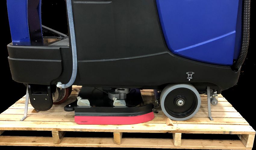
30 GALLON RIDER AUTO SCRUBBER SPECIFICATIONS
Features Specifications
Model RS28 (Disk) RS28 (Orbital)
Machine Specifications
Length 60 in (152.4 cm) 60 in (152.4 cm)
Width (w/o Squeegee) 27 in (68.6 cm) 27 in (68.6 cm)
Height 52 in (132.1 cm) 52 in (132.1 cm)
Weight w/ Std Batteries 920 lbs (417.5 kg) 920 lbs (417.5 kg)
Sound level 65 dBA 65 dBA
Rotationally Molded Polyethylene Tanks Rotationally Molded Polyethylene Tanks
Construction
Powder Coated Steel Frame Powder Coated Steel Frame
Drive System
Drive type 9.84 in (250 mm) motor in wheel 9.84 in (250 mm) motor in wheel
Motor horsepower 1.13 HP / 840 W 1.13 HP / 840 W
Throttle Pedal Throttle Pedal
Speed Control
5 Max Speed Settings 5 Max Speed Settings
Speed (Scrubbing) 310 fpm (5.7 km/h) 310 fpm (5.7 km/h)
Speed (Transport) 310 fpm (5.7 km/h) 310 fpm (5.7 km/h)
Speed (Reverse) 248 fpm (4.5 km/h) 248 fpm (4.5 km/h)
Scrubbing Grade 2% 2%
Transport Grade (Full) 10% 10%
Transport Grade (Empty) 19% 19%
Solution Delivery System
Solution Capacity 30 gal (133.6 l) 30 gal (133.6 l)
Solution Control (Standard) 0.1 - .8 gpm (0.005 - 0.037 kg/sec) 0.1 - .8 gpm (0.005 - 0.037 kg/sec)
Solution Control Settings 5 5
Chemical injection (Opt’l) 12 Settings 12 Settings
Scrubbing System
Cleaning Path 28 in (71.1 cm) 28 in (71.1 cm)
Pad Brush Size (2) 14 in (35.6 cm) Disk 14 in (35.6 cm) x 28 in (71.1 cm) Pad
90 lbs (40.8 kg), 120 lbs (54.4 kg), 150 lbs (68 kg), 180 lbs (81.6 kg), 90 lbs (40.8 kg), 120 lbs (54.4 kg), 150 lbs (68 kg), 180 lbs (81.6 kg),
Pressure
and 210 lbs (95.3 kg) and 210 lbs (95.3 kg)
Productivity (Per Hour) Theoretical Max 49,238 sq-ft (4,573 sq-m) 49,238 sq-ft (4,573 sq-m)
Productivity (Per Hour) Average Coverage Rate* 25,566 sq-ft (2,378 sq-m) 25,566 sq-ft (2,378 sq-m)
Recovery System
Recovery Tank Capacity 32 gal / 121 L 32 gal / 121 L
Recovery Tank Accessibility Full Clean-out Access Full Clean-out Access
Vacuum Motor .76 Hp / 566 W, 3-Stage .76 Hp / 566 W, 3-Stage
Vacuum Motor cfm/cmm 68 cfm (1.92 cubic m/min) 68 cfm (1.92 cubic m/min)
Vacuum Motor Water-lift 71 in (180 cm) 71 in (180 cm)
Squeegee Width 33 in (84 cm) 33 in (84 cm)
Squeegee Material (Std) Linatex® Linatex®
Squeegee Material (Opt’l) PRIMOthane® PRIMOthane®
Battery System
System Voltage 24 V 24 V
Battery Amp/Hour Rating (Std) 260 Ah 260 Ah
Battery Run Time (Std) Up to 3.0 hours Up to 3.5 hours
Battery Amp/Hour Rating (Opt’l) 360 Ah 360 Ah
Battery Run Time (Opt’l) Up to 5.0 hours Up to 5.5 hours
Battery Amp/Hour Rating (MF) 250 Ah 250 Ah
Battery Run Time (MF) Up to 2.5 hours Up to 3.0 hours
Charger Description On-Board On-Board
*Productivity calculations utilize key factors from ISSA 540 cleaning times handbook
Note: Specifications subject to change without notice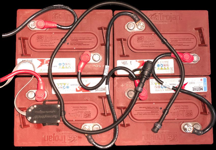
TABLE OF CONTENTS
SAFETY INFORMATION���������������������������������������������������������������������������������������������������������������������������������������������������1
UNPACKING THE MACHINE�������������������������������������������������������������������������������������������������������������������������������������������3
TRANSPORTING THE MACHINE�����������������������������������������������������������������������������������������������������������������������������������3
BATTERIES���������������������������������������������������������������������������������������������������������������������������������������������������������������������������4
    SERVICING LEAD ACID BATTERIES (NON-HYDROLINK® MODELS)��������������������������������������������������������������5
    SERVICING LEAD ACID BATTERIES WITH HYDROLINK® WATERING SYSTEM�������������������������������������������6
    BATTERYSHIELD® AUTOMATED WET BATTERY PROTECTION SYSTEM�����������������������������������������������������6
    CLEANING THE BATTERYSHIELD® SENSOR LIGHT PIPE���������������������������������������������������������������������������������7
CHARGING���������������������������������������������������������������������������������������������������������������������������������������������������������������������������8
   CHARGER SETTINGS�������������������������������������������������������������������������������������������������������������������������������������������������8
OPERATION��������������������������������������������������������������������������������������������������������������������������������������������������������������������������9
    MACHINE OVERVIEW�����������������������������������������������������������������������������������������������������������������������������������������������9
    CONTROL PANEL������������������������������������������������������������������������������������������������������������������������������������������������������10
    MACHINE ERROR CODES��������������������������������������������������������������������������������������������������������������������������������������� 11
    DRIVE SYSTEM���������������������������������������������������������������������������������������������������������������������������������������������������������12
    SOLUTION DISTRIBUTION�������������������������������������������������������������������������������������������������������������������������������������12
    SCRUB HEAD������������������������������������������������������������������������������������������������������������������������������������������������������������14
    ORBITAL SCRUB HEAD & CHEMICAL-FREE FINISH REMOVAL�������������������������������������������������������������������14
    DISK SCRUB HEAD��������������������������������������������������������������������������������������������������������������������������������������������������15
    RECOVERY SYSTEM������������������������������������������������������������������������������������������������������������������������������������������������16
RECOMMENDED MAINTENANCE�������������������������������������������������������������������������������������������������������������������������������19
RECOMMENDED SERVICE PARTS������������������������������������������������������������������������������������������������������������������������������21
TROUBLESHOOTING GUIDE����������������������������������������������������������������������������������������������������������������������������������������23
PARTS DIAGRAMS������������������������������������������������������������������������������������������������������������������������������������������������������������25
    FRAME ASSEMBLY��������������������������������������������������������������������������������������������������������������������������������������������������25
    SOLUTION TANK������������������������������������������������������������������������������������������������������������������������������������������������������28
    STEERING COLUMN������������������������������������������������������������������������������������������������������������������������������������������������29
    RECOVERY SYSTEM������������������������������������������������������������������������������������������������������������������������������������������������31
    HEAD LIFT�����������������������������������������������������������������������������������������������������������������������������������������������������������������33
    BATTERY��������������������������������������������������������������������������������������������������������������������������������������������������������������������35
    BATTERY CHARGER������������������������������������������������������������������������������������������������������������������������������������������������36
    SEAT ASSEMBLY�������������������������������������������������������������������������������������������������������������������������������������������������������37
    DISK SCRUB HEAD��������������������������������������������������������������������������������������������������������������������������������������������������39
    ORBITAL SCRUB HEAD�������������������������������������������������������������������������������������������������������������������������������������������41
    SIDE SQUEEGEE�������������������������������������������������������������������������������������������������������������������������������������������������������43
    SQUEEGEE LIFT��������������������������������������������������������������������������������������������������������������������������������������������������������45
    SQUEEGEE�����������������������������������������������������������������������������������������������������������������������������������������������������������������46
    CONTROLLER�����������������������������������������������������������������������������������������������������������������������������������������������������������47
    ELECTRICAL HARNESSES�������������������������������������������������������������������������������������������������������������������������������������48
ELECTRICAL DIAGRAMS����������������������������������������������������������������������������������������������������������������������������������������������49
SAFETY INFORMATION
WARNING: A potentially hazardous situation that, if not avoided, could result in death or serious injury.

 CAUTION: A potentially hazardous situation that, if not avoided, could result in moderate injury or serious property
         damage.

NOTE: Information that will prevent premature equipment failure or minor property damage.

WARNING:      This product can expose you to chemicals including lead and lead compounds which are known to the State
              of California to cause cancer and birth defects or other reproductive harm. For more information go to www.
              P65Warnings.ca.gov.
WARNING:      This machine is not equipped with explosion proof motors. Never use near flammable or reactive materials, liquids,
              vapors or combustible dusts. Electric motors spark internally during operation and could cause a flash fire or explosion.
WARNING:      Batteries emit hydrogen and oxygen gas.
                • Keep sparks and open flame away.
                • Do not smoke near the machine.
                • Charge batteries in a well-ventilated area with the battery compartment open.
WARNING:      Do not plug in the charger cable if wall cord or battery harness is damaged.
WARNING:      Disconnect battery cables before servicing.
WARNING:      Do not wear jewelry when working near moving or electrical components.
WARNING:      Do not use the machine as a means for transport.
WARNING:      Never allow children to play on or around machine.
WARNING:      Do not bump into shelves or scaffoldings, especially where there is a risk of falling objects.
WARNING:      Support the machine on safety stands before working underneath.
WARNING:      Do not operate the machine:
                • Unless trained and authorized.
                • Unless operator manual has been fully read and understood.
                • While using cell phones or other electronic devices.
                • Under the influence of drugs or alcohol.
                • With any part of the machine not functioning properly.
                • With the brake disabled.
                • In areas where flammable vapors, liquids, or combustible dusts are present.
                • In low light areas where the operators vision is impaired.
                • In areas with possible falling objects.
WARNING:      Before operating the machine:
                • Check the machine and batteries for fluid leaks.
                • Check the steering and brake systems for proper operation.
WARNING:      While operating the machine:
                • Operate the machine only as described in this manual.
                • Allow the machine to fully stop before getting off.
                • Keep all body parts inside the machine while moving.
                • Do not carry passengers on the machine.
                • Follow all safety instructions and guidelines specific to your facility or environment.

                                                                                                                           RETURN TO
                                                                                                                            TABLE OF
 -1-                                                                                                                       CONTENTS
SAFETY INFORMATION
                                                       CONTINUED
CAUTION:     Keep hands away from spinning brushes.
CAUTION:     Do not modify the machine from its original design.
CAUTION:     Wear non-slip shoes when operating machine.
CAUTION:     Reduce speed when turning or operating on inclines and slippery surfaces.
CAUTION:     Use Bromine only in your tank treatment system! Do not use chlorine. Chlorine can interact with ammonia-based
             detergents and cause harmful fumes.
CAUTION:     Follow mixing and handling instructions on chemical containers.
CAUTION:     Remove the batteries, use a jack, and get assistance before lifting the machine.
CAUTION:     Park and service the machine on a level surface and remove the key.
CAUTION:     Always wear protective clothing, gloves and goggles when handling and charging batteries.
CAUTION:     Avoid moving parts and do not wear loose jackets, shirts or sleeves when servicing.

NOTE:        Do not hose down or use a power-spray on the machine. Electrical malfunction may occur.
NOTE:        All repairs must be performed by a qualified service technician using approved replacement parts.
NOTE:        To avoid damaging the floor, do not allow the brush/pad to operate while the machine is stationary.
NOTE:        Use a ramp with no more than a 12% incline when loading or unloading the machine.
NOTE:        Use tie down straps to secure the machine to the truck or trailer during transport.
NOTE:        Discontinue use and report machine damage or faulty operation immediately.
NOTE:        Store the machine indoors where the temperature is between 32º and 104ºF (0º and 40ºC).
NOTE:        Do not lower the orbital head without a pad. Doing so damages the Mighty-Lok® face.
NOTE:        Failure to clean the BatteryShield® light pipe will limit the system’s ability to read the water level and will reduce
             battery life.
NOTE:        Do not use an extension cord. This will void the warranty on the charger.
NOTE:        Batteries designed for automotive or marine and RV use are not suited for use in floor scrubbers.
NOTE:        Use of an unapproved water supply or modification of an approved water supply can lead to battery system failure.
NOTE:        Ensure battery charging and storage locations comply with OSHA and any governing agencies’ standards based on
             your particular location and application.
NOTE:        When loading/unloading machine for transport:
               • Fully drain the Solution and Recovery tanks before loading.
               • Transport the machine with the scrub head in the raised position.
               • Ensure the ramp and truck/trailer are properly rated for the weight of the machine.
               • Do not lower the Orbital Scrub Head without a pad installed.
               • Chock the wheels and tie down the machine.
               • Actuate the Manual Brake Release lever before attempting to manually push/move the machine.

 RETURN TO
  TABLE OF
 CONTENTS                                                                                                                       -2-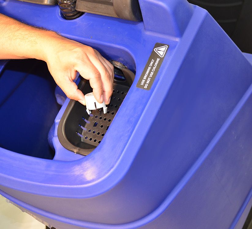
UNPACKING THE MACHINE
1.    Remove outer cardboard packaging.
2.    Remove the shrink wrap securing the ramp and allow the ramp (not shown) to lower to the ground.
3.    Using a #2 Philips driver, remove the screws from the front and rear wood wheel chocks.
4.    Using a 3/8” socket and driver or wrench, remove the screws from the tie-down straps located at each corner of the machine.
5.    Turn the machine on using the key switch and carefully drive down the ramp.
6.    Install the rear squeegee assembly (refer to the RECOVERY SYSTEM of this manual).

                        TRANSPORTING THE MACHINE
NOTE: Fully drain the Solution and Recovery tanks before loading.
NOTE: Ensure the ramp and truck/trailer are properly rated for the weight of the machine.
NOTE: Use a ramp with no more than a 12% incline to load and unload the machine.
NOTE: Transport the machine with the scrub head in the raised position.
NOTE: Do not lower the Orbital Scrub Head without a pad installed. Doing so will damage the Mighty-Lok® face.
NOTE: Remove the rear squeegee assembly before transporting the machine.
NOTE: Chock the wheels and tie down the machine.
NOTE: Actuate the Manual Brake Release lever before attempting to manually push/move the machine.

Six (6) tie-down points (two on the front, two at the
front corners, and two at the rear corners) have been
provided on the frame to allow the machine to be
secured during transportation.

Ensure the machine is properly secured with suitable
tie-down straps before transporting the machine.

                                                                                                                           RETURN TO
                                                                                                                            TABLE OF
     -3-                                                                                                                   CONTENTS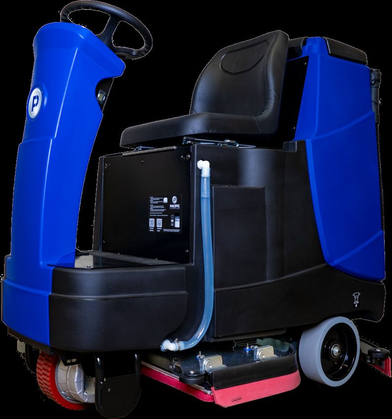
BATTERIES
WARNING: Battery posts, terminals, and related accessories contain lead and lead compounds, chemicals known to the State of
         California to cause cancer and reproductive harm, and during charging, strong inorganic acid mists containing sulfuric
         acid are involved, a chemical known to the State of California to cause cancer. Wash hands after handling. For more
         information go to www.P65Warnings.ca.gov.
WARNING:          Batteries emit hydrogen and oxygen gas.
                    • Keep sparks and open flame away.
                    • Do not smoke near the machine
                    • Charge batteries in a well-ventilated area with the battery compartment open
WARNING:          Do not wear jewelry when working near moving or electrical components.

CAUTION:          Park and service the machine on a level surface and remove the key.
CAUTION:          Always wear protective clothing, gloves and goggles when handling and charging batteries.
NOTE:             All repairs must be performed by a qualified service technician using approved replacement parts.
NOTE:             Failure to clean the BatteryShield® light pipe will limit the system’s ability to read the water level and will reduce
                  battery life.
NOTE:             Batteries designed for automotive or marine and RV use are not suited for use in floor scrubbers.

         SELECTION
The machine requires four 6V Lead Acid or AGM Deep Cycle batteries designed for use in floor scrubbers applications. Maximum
battery dimensions are:
• Width: 6.85” (174mm)
• Length: 12.17” (309mm)
• Height:14.41” (366mm)

         INSTALLATION
1.     Open the Seat Assembly and the Recovery Tank.
2.     Use a lifting device capable of lifting and transporting the batteries safely.
3.     Move the batteries into position (as shown below).
4.     Connect the batteries in a series to obtain an overall voltage of 24V.
5.     Fully charge the batteries before use.
     FRONT

     RETURN TO
      TABLE OF
     CONTENTS                                                                                                                          -4-
SERVICING LEAD ACID BATTERIES (NON-HYDROLINK® MODELS)
          REQUIRED EQUIPMENT
•    Eye protection
•    Acid resistant gloves
•    Distilled water
•    Baking soda to neutralize acid spills

          SAFETY
NEVER:
• Add acid to a battery.
• Smoke near batteries.
• Charge a frozen battery.
• Leave an acid spill unattended.
• Store batteries unless they are fully charged.
• Charge a battery when the temperature is above 122°F (50°C).
• Charge a flooded battery without securing vent caps on the cells.
• Place objects on top of batteries, which can cause a short circuit.
ALWAYS:
• Neutralize acid spills with baking soda and water.
• Use insulated tools to verify connections are tight.

          WATERING
•    If contact with electrolyte (sulfuric acid) occurs, flush with large amounts of water.
•    Use only distilled water (tap water can contain contaminants that will damage the
     battery).
•    Remove the caps and place them upside down to check electrolyte levels.
•    For discharged or partially charged batteries, add just enough water to cover the
     plates.
•    Fully charge the batteries.
•    Add distilled water to a level of 1/8” (0.125”) below the vent well.

          CLEANING & INSPECTION
•    Fluid on the top of a battery may mean it is being over-watered or overcharged.
•    Check cleanliness and keep terminals and connectors free of corrosion.
•    Clean with a solution of one cup baking soda to one gallon of water.
•    Do not allow cleaning solution to get inside the battery.
•    Rinse with water and dry with a clean cloth.
•    Keep the area around batteries clean and dry.
•    Properly secure all vent caps.
•    Check battery cables and connections. Replace any damaged cables and tighten any loose connections.

                                                                                                           RETURN TO
                                                                                                            TABLE OF
    -5-                                                                                                    CONTENTS
SERVICING LEAD ACID BATTERIES WITH HYDROLINK® WATERING
                            SYSTEM
1.     Position the container of distilled water below the level of the top of the batteries to prevent siphoning.
2.     Place the end of the watering system hose in the distilled water and squeeze the bulb to fill the system.
3.     Remove the dust cover from the Hydrolink® snake connected to the batteries.
4.     Connect the coupler on the Hydrolink® snake to the coupler on the watering system using the quick disconnect fittings.
5.     While squeezing the hand pump, observe the flow indicator (spinning red balls). As the batteries begin to fill, the spinning of the
       flow indicator balls will slow. Batteries are full when the flow indicators completely stop spinning.
NOTE: Battery systems may take more than 1/2 gallon of water once the BatteryShield® light has illuminated. Failure to actuate the
      hand pump until the flow indicator stops spinning will result in batteries being under or unevenly serviced which will reduce
      battery life.
6.     When the flow indicator stops, and not before, disconnect the coupler by depressing the push button on the watering system
       coupler.
NOTE: Leaving the watering system connected could result in the batteries being over filled. Disconnecting the watering system
      before the flow indicator stops spinning will result in batteries being under serviced and battery life will be reduced.
7.     Replace the dust cover on the Hydrolink® snake.

         BATTERYSHIELD® AUTOMATED WET BATTERY PROTECTION
                             SYSTEM
Machines equipped with BatteryShield® technology have a sensor installed on one of the battery caps and a red LED indicator located
on the Control Panel. This sensor monitors the water level in the batteries and the LED communicates to the operator that the batteries
require servicing. When the BatteryShield® LED is lit, the scrub head is disabled until battery servicing has been performed.

• When the key switch is turned on, the BatteryShield® system will check the water level of the batteries.
  • If the LED turns off, there is sufficient water in the batteries.
  • If the LED remains on (without flashing), the batteries require servicing and the scrub head will not run.
  • If the LED flashes intermittently, the BatteryShield® light pipe must be cleaned (instructions below).
NOTE: Failure to clean the BatteryShield® light pipe will limit the system’s ability to read the water level and will reduce battery life.
• If the BatteryShield® LED indicates the need for servicing, turn off the key switch and service the batteries as described above.
• After completing the Hydrolink® watering system procedure, turn the key switch back on and verify the LED turns off.

     RETURN TO
      TABLE OF
     CONTENTS                                                                                                                        -6-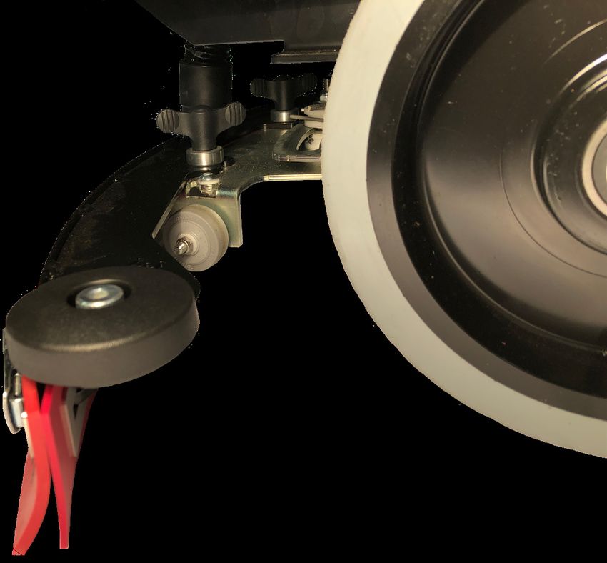
CLEANING THE BATTERYSHIELD® SENSOR LIGHT PIPE
CAUTION:         Always wear protective clothing, gloves and goggles when handling and charging batteries.
NOTE:            All repairs must be performed by a qualified service technician using approved replacement parts.

1.    Locate and remove the battery cap with the BatteryShield® sensor module.
NOTE: Never remove the BatteryShield® sensor from the battery cap. Doing so will cause the BatteryShield® system to function
      improperly.
NOTE: Take care not to damage the battery cap floats or the BatteryShield® sensor light pipe.
2.    Thoroughly wipe the clear BatteryShield® light pipe with a clean rag, giving special attention to the tip.
3.    With the battery cap still removed, cycle the key switch on to verify that the BatteryShield® LED remains on.
4.    Turn off the key switch.
5.    Carefully install the battery cap.
NOTE: Whenever the battery cap is removed, ensure the Hydrolink® snake port is fully seated in the cap when maintenance is
      complete.
6.    Complete the Hydrolink® watering procedure described above.
7.    Turn on the key switch and verify the light remains off.
8.    The machine is ready for use.

                                                                                                                      RETURN TO
                                                                                                                       TABLE OF
     -7-                                                                                                              CONTENTS
CHARGING
WARNING: Batteries emit hydrogen and oxygen gas.
• Keep sparks and open flame away.
• Do not smoke near the machine.
• Charge batteries in a well-ventilated area with the battery compartment open.
WARNING: Do not wear jewelry when working near moving or electrical components.
WARNING: Do not plug in the charger cable if wall cord or battery harness is damaged.
NOTE: Do not use an extension cord with the battery charger. This will void the charger warranty.
NOTE: Ensure battery charging and storage locations comply with OSHA and any governing agencies’ standards based on
your particular location and application.
NOTE: Seat assembly must remain open while charging to prevent damage to the charger power cord.
This machine is equipped with an on-board charger. The cord for the charger can be located in the cord storage compartment under the
seat.
The charger status LED’s (used to indicate the charger’s status while plugged in) can be viewed through the view window located on
the vertical kick panel below the seat.
LED INDICATION MEANING
GREEN flashing (2 seconds) Charger is set for AGM batteries
YELLOW flashing (continuous) Unsuitable battery connected or output short circuit
RED flashing (2 seconds) Charger is set for Lead Acid batteries
RED flashing (continuous) Safety timer exceeded or internal short circuit
Solid GREEN The unit is fully charged
Solid YELLOW Phase 2 of charging is in progress
Solid RED Charging cycle has begun
CHARGER SETTINGS
SW1: Sets the current profile of the charger to the particular battery that is installed.
SW1
DP2 DP1 APPLICATION
OFF ON LEAD-ACID (WET) BATTERIES
OFF OFF AGM (MAINTENANCE FREE)
SW2: Set the current level of the charger based on the
amp-hour rating for the particular batteries installed.
SW2
DP2 DP1 CHARING CURRENT
ON OFF 20A
OFF ON 25A
OFF OFF 25A
CHARGING CURRENT BATTERY AMP HOUR RANGE (20h)
20A 150-240 Ah
25A 220-315 Ah
RETURN TO
TABLE OF
CONTENTS -8-OPERATION
MACHINE OVERVIEW
A. SEAT ASSEMBLY P. CHARGER STATUS VIEW WINDOW
B. STEERING WHEEL Q. SEAT ADJUSTMENT
C. STEERING WHEEL ADJUSTMENT R. HOUR METER & (OPTIONAL) LAMP SWITCH
D. CONTROL PANEL S. SQUEEGEE HOSE
E. KEY SWITCH T. RECOVERY VACUUM MOTOR & HEPA FILTER
(LOCATED BEHIND COVER)
F. THROTTLE PEDAL
U. RECOVERY DRAIN HOSE
G. DRIVE WHEEL
V. SOLUTION TANK FILL PORT
H. MANUAL BRAKE RELEASE
W. SOLUTION SHUT-OFF VALVE & SOLUTION FILTER
I. SCRUB HEAD (LOCATED UNDER SOLUTION TANK)
J. SIDE SQUEEGEE X. REAR WHEELS
K. SQUEEGEE ASSEMBLY Y. SOLUTION TANK LEVEL INDICATOR
L. CUP HOLDER & TOOL STORAGE
M. RECOVERY TANK
N. RECOVERY TANK LID
O. (OPTIONAL) LAMP
RETURN TO
TABLE OF
-9- CONTENTSCONTROL PANEL
Zone 1: Modes of Operation
• SCRUB ONLY: Allows the operator to run the scrub head only.
• VACUUM ONLY: Allows the operator to run the squeegee/vacuum system only.
• VACUUM + SCRUB: Allows the operator to run both the scrub head and squeegee/vacuum systems.
Zone 2: Operational Settings
• DOWN PRESSURE: Increases (“+”) or decreases (“-”) the down-pressure force of the scrub head.
• SOLUTION FLOW: Increases (“+”) or decreases (“-”) the amount of solution being dispensed at the scrub head.
• MAX SPEED: Increases (“+”) or decreases (“-”) the maximum speed when the throttle pedal is fully pressed.
• CHEMICAL INJECTION (OPTIONAL): Increases (“+”) or decreases (“-”) the ratio of chemical added to the solution as it is
dispensed at the scrub head
Zone 3: Machine Status
• BATTERY INDICATOR: LED display indicating current battery level and/or potential machine errors. See error indicator chart.
• SOLUTION EMPTY: LED display indicates when the solution tank is empty.
• BATTERYSHIELD®: On BatteryShield® equipped machines, LED display indicates battery maintenance is required.
• SCRUB ONLY: LED display is lit when machine is running in SCRUB ONLY to remind operator that they are leaving a wet
floor behind the machine
Zone 4: Machine Controls
• FORWARD: Enables the machine to drive forward.
• REVERSE: Enables the machine to drive in reverse.
• HORN: Press and hold to sound the horn.
RETURN TO
TABLE OF
CONTENTS - 10 -MACHINE ERROR CODES
The battery needs charging or there is a bad connection to the battery. Check the connections to the battery. If the
connections are good, try charging the battery.
There is a bad connection to the Traction motor. Check all connections between the motor and the control system.
There is a bad connection to the Brush motor/motors. Check all connections between the motor/motors and the
control system.
Refer to the 4-Bar flash sequence table below.
There is a bad connection to the Vacuum motor. Check all connections between the motor and the control system.
The control system is being inhibited from driving.
Refer to the 7-Bar flash sequence table below.
A control system trip is indicated. Make sure that all connections are secure.
Refer to the 9-Bar flash sequence table below.
Excessive voltage has been applied to the control system. This is usually caused by a poor battery connection. Check
the battery connections.
1 Flash: Inspect the Head Lift System. Check that the actuator is functioning properly and that there are no mechanical
interferences. Check all associated sensors, connectors, and wiring.
2 Flash: Inspect the Squeegee Lift System. Check that the actuator is functioning properly and that there are no mechanical
interferences. Check all associated connectors and wiring.
1 Flash: Inspect Throttle System. Ensure that the throttle is in the rest position before switching on the machine. Check all
associated connectors and wiring.
3 Flash: Inspect the Brake System. Ensure the manual brake override is not engaged.
1 Flash: Inspect the Lamp System. Check that the lamp is not damaged. Check all associated connectors and wiring.
3 Flash: Inspect the Solution Pump. Ensure that the pump is functioning properly. Check all associated connectors and
wiring.
4 Flash: Inspect the Solution Valve and Hour Meter Systems. Ensure that the valve and hour meter are not damaged and are
functioning properly. Check all associated connectors and wiring.
5 Flash: Inspect the Brake System. Ensure the brake is functioning properly. Check all associated connectors and wiring.
RETURN TO
TABLE OF
- 11 - CONTENTSDRIVE SYSTEM
1. Turn the machine on using the key switch located on the right side of the steering column.
2. Set the desired maximum speed using the MAX SPEED selector on the Control Panel
3. Select the desired direction of travel using the FORWARD and REVERSE selectors on the Control Panel.
4. Maintain control of the Steering Wheel at all times during operation.
5. Depress the Throttle Pedal to engage the drive system.
NOTE: The speed of the machine is based on the relative amount the throttle is depressed. The MAX SPEED selector governs the
maximum speed the machine will travel with the throttle fully depressed.
NOTE: The machine is equipped with a sensor which reduces the maximum speed while in sharp turns. After the steering wheel is
straightened, the machine will return to the full maximum speed as regulated by the MAX SPEED selector.
The machine can be moved manually (pushed or pulled) if absolutely necessary. Before attempting to move the machine manually,
fully actuate the Manual Brake Release located on the right side of the Drive Wheel. The Manual Brake Release lever must be fully
actuated the entire time the machine is being moved. Failure to fully actuate the Manual Brake Release lever could cause damage to
the Drive Wheel and brake system.
SOLUTION DISTRIBUTION
FILLING THE SOLUTION TANK
Use liquid detergent in the concentration and manner specified by the manufacturer for a
30-gallon solution tank. Excess foam will damage the vacuum motor. In addition to properly-
mixed low-foam detergent, use a small amount of de-foaming liquid in the recovery tank. Never
use pure acids.
1. Add water and cleaning agent via the fill port located under the Seat Assembly. Water should
not exceed 120°F (50°C).
2. Monitor the level of the solution through the sight tube located on the side of the machine.
3. To drain the solution tank, slide the sight tube off of the upper fitting and lower the tube into
drain or mop sink.
SOLUTION FLOW
Solution flow is controlled by the SOLUTION FLOW selector located on the Control Panel.
Solution is delivered at a rate of 0.1 - 0.8 gpm (0.005 - 0.037 kg/sec) based upon the SOLUTION
FLOW setting and the speed of the machine (flow rate increases or decreases with machine
speed to prevent over/under distribution).
When the machine senses that the solution tank is empty, the SOLUTION EMPTY LED
will illuminate and the scrub head will turn off.
RETURN TO
TABLE OF
CONTENTS - 12 -CHEMICAL INJECTION
For machines equipped with the optional chemical injection system:
1. Place a 1-gallon chemical container in the holder (located behind the battery
compartment, under the Recovery Tank).
2. Insert the hose into the container so that the filter at the end of the hose rests on the
bottom of the container.
3. Screw on the cap.
4. Match the mix ratio dial on the Control Panel to the setting (in ounces per gallon)
prescribed by the chemical manufacturer.
5. Set the SOLUTION FLOW selector to the desired flow setting.
6. Operate the machine as normal.
NOTE: If the chemical is not priming, temporarily set the mix ratio to a higher setting until
the chemical is delivered.
NOTE: To purge chemical, remove the hose from the chemical container, set the mix ratio
dial to the highest setting, and run until the hose is drained.
INSPECTION & CLEANING
To clean out the solution tank in the case of excessive debris:
1. Close the shutoff valve (located under the left rear tire).
2. Remove the filter bowl and screen (located forward of the
shutoff valve).
3. Open the shutoff valve and allow the tank to drain.
4. Rinse the solution tank thoroughly.
5. Install the filter bowl and screen.
RETURN TO
TABLE OF
- 13 - CONTENTSSCRUB HEAD
Running the machine in SCRUB ONLY or VACUUM+SCRUB will lower the scrub head to the floor. The scrub head motors will
begin running when the throttle pedal is depressed. Scrub head down pressure is set using the DOWN PRESSURE selector on the
Control Panel. See the chart below for down-pressure forces.
SETTING DOWN-PRESSURE
1 90 lbs (40.8 kg)
2 120 lbs (54.4 kg)
3 150 lbs (68 kg)
4 180 lbs (81.6 kg)
5 210 lbs (95.3 kg)
ORBITAL SCRUB HEAD & CHEMICAL-FREE FINISH REMOVAL
NOTE: Do not operate the Orbital Scrub Head without a pad installed. Operating the head without a pad will damage the Mighty-
Lok® face.
STANDARD OPERATION
1. With power off and the Scrub Head raised, lift the Side
Squeegees to the raised position.
2. Align the corners of the pad to the corners of the aluminum
plate with Mighty-Lok® face and press to attach.
3. Lower the scrub deck onto the pad (by turning power on the
machine and selecting SCRUB ONLY or VACUUM+SCRUB
mode).
4. Ensure the pad is properly aligned front-to-back and right-to-
left. Water should drip directly onto the top of the pad.
5. Lower the Side Squeegees.
6. The machine is ready for operation.
CHEMICAL-FREE FINISH REMOVAL (CFR) PAD ASSEMBLY & OPERATION
In addition to the traditional cleaning pad, a specialized surface preparation pad is required for chemical-free finish removal. The
standard red scrub pad acts as a “backer” and compensates for variances in the floor.
1. Place the black retainer pad 2” back from the front of the red
scrub pad.
2. Align the maroon CFR pad with the red scrub pad.
3. Ensure the pads are aligned so that the black pad is justified
towards the back of the machine, so that the gap described in Step
1 is towards the front of the machine.
4. Install the pads in accordance with the instructions above for
standard operation.
5. Fill the Solution Tank with clean water.
6. Set the DOWN PRESSURE selector to the maximum setting.
7. Set the SOLUTION FLOW to the medium setting. Adjust as
needed to obtain the optimum finish removal using the least
amount of water for effective rinsing.
8. Set the MAX SPEED selector to the lowest setting.
RETURN TO
TABLE OF
CONTENTS - 14 -DISK SCRUB HEAD
STANDARD OPERATION
NOTE: Do not operate the Disk Scrub Head without a pad installed on the pad driver. Operating the head without a pad will damage
the floor.
1. With power off and the Scrub Head raised, lift the Side Squeegees to the raised position.
2. Align the pad driver assemblies with the bayonet drivers on the machine.
3. Lower the scrub head onto the pad driver assemblies (by turning power onto the machine and selecting SCRUB ONLY or
VACUUM+SCRUB mode).
4. Ensure the bayonet drivers are properly engaged with the pad driver assemblies.
5. Lower the Side Squeegees.
6. Drive the machine forward and listen for the bayonet drivers to lock onto the pad driver assemblies.
7. The machine is ready for operation.
DISK REMOVAL
1. With power off and the Scrub Head raised, lift the Side Squeegees to the raised position.
2. Grab the pad driver assemblies and rotate by hand to disengage from the bayonet drivers.
3. Lower the Side Squeegees.
RETURN TO
TABLE OF
- 15 - CONTENTSRECOVERY SYSTEM
RECOVERY TANK
To drain and rinse the recovery tank:
1. Remove the Recovery Drain Hose from the holder and lower the end into the drain location.
2. Remove the press-fit cap from the Recovery Drain Hose, squeezing the restriction collar to control the flow.
3. As the tank drains, lean the Recovery Tank back and open the lid.
4. Using clean water, thoroughly clean and rinse out any sediment in the Recovery Tank.
NOTE: Periodically use cleaner and sanitizer with a cloth or sponge to prevent mold and mildew.
5. Inspect and clean the debris tray and the vacuum the mesh filter screen around the ball float system.
6. Leave the lid open to dry.
TANK TREATMENT SYSTEM
The Tank Treatment System (TTS) uses Bromine tablets (typically used in pools and spas) to kill the odor-causing bacteria in the tank.
To ensure that the TTS is prepared to treat your recovery tank:
1. Lift the debris tray out and pinch the two tabs sticking through the underside of the tray.
2. Check the size of the Bromine puck. Replace it when it is approximately 25% of its original size.
3. Press the TTS holder and bromine puck back into the debris tray.
CAUTION: Use Bromine only! Do not use chlorine! Chlorine can interact with ammonia-based detergents to cause harmful fumes.
RETURN TO
TABLE OF
CONTENTS - 16 -SQUEEGEE SYSTEM
Squeegee Blades and system should be inspected and maintained regularly to achieve peak machine performance.
REMOVAL & INSTALLATION
Install: Align the slots in the squeegee assembly with the easy-grip knobs, attach the vacuum hose, and tighten the knobs.
Remove: Loosen the easy-grip knobs, remove the vacuum hose, and remove the assembly.
SQUEEGEE USE
Operating the machine in either VACUUM ONLY or VACUUM + SCRUB mode will cause the Squeegee Actuator to lower the
assembly and the vacuum motor to turn on. Deselecting VACUUM ONLY or VACUUM + SCRUB mode will cause the squeegee
assembly to lift and the vacuum motor to shut off after a 60 second delay. This delay ensures all of the recovered water is pulled into
the recovery tank.
SQUEEGEE ADJUSTMENT
Improper adjustment of the squeegee blades will reduce the systems ability to properly pick up water. The leading edge of the rear
squeegee blade should contact the floor at a 45° angle (similar to the image shown below). The height of the squeegee system is
adjusted using the two cap head screws located next to the easy-grip knobs. Raise (by turning the screws clockwise) or lower (by
turning the screws counter-clockwise) until the proper blade deflection is achieved. When the system is adjusted properly, the small
gray wheels on the squeegee system should be approximately 1/32” off of the floor.
RETURN TO
TABLE OF
- 17 - CONTENTSINSPECTION & CLEANING
1. Inspect both squeegee blades. Blades edges are considered worn if the edge is not clearly
defined or if the edge is worn halfway through the thickness of the blade. Blades can be
flipped and rotated to use all four edges.
2. Thoroughly clean the blades, frame, and neck of any debris.
SQUEEGEE BLADE REPLACEMENT
1. Release the over-center latch and slide the band clamp off the hook on the other side.
NOTE: Blades can be flipped and rotated so as to use all four edges.
2. Blade installation is the reverse of the removal.
RETURN TO
TABLE OF
CONTENTS - 18 -RECOMMENDED MAINTENANCE
SYSTEM DAILY WEEKLY MONTHLY BIANUALLY
CONTROL PANEL/STEERING
INSPECT ALL CONTROLS AND HARDWARE FOR SECURITY & SERVICEABILITY X
VERIFY THROTTLE PEDAL FUNCTION X
VERIFY PROPER OPERATION OF ALL CONTROLS X
VERIFY FUNCTION OF STEERING SYSTEM X
INSPECT AND LUBRICATE U-JOINT X
SOLUTION DISTRIBUTION
VERIFY SOLUTION FLOW & ADJUSTMENT OPERATION X
CLEAN & INSPECT INLINE FILTER X
FLUSH TANK WITH FRESH WATER X
VERIFY FLOAT SWITCH FUNCTION BY DRAINING TANK X
SCRUB DECK
RINSE BRUSHES & PADS X
RINSE & DRY SCRUB DECK X
CLEAN MOTOR VENTS X
INSPECT ISOLATORS *(ORBITAL ONLY) X
INSPECT LIFT LINKAGE & ACTUATOR X
RECOVERY SYSTEM
RINSE & AIR DRY RECOVERY TANK X
CLEAN & INSPECT DEBRIS TRAY X
VERIFY DRAIN HOSE CAP IS SEALED TIGHT WHEN INSTALLED X
INSPECT LID SEAL X
INSPECT / REPLACE BROMINE PUCK X
INSPECT HEPA FILTER X
CLEAN & SANITIZE RECOVERY TANK X
BATTERIES AND CHARGER
INSPECT TERMINALS & CABLES FOR SECURITY, CORROSION & DAMAGE X
SERVICE LEAD ACID BATTERIES *(IF EQUIPPED) X
CLEAN BATTERYSHIELD® LIGHT PIPE *(IF EQUIPPED) X
PERFORM BATTERYSHIELD® OPERATIONAL CHECK *(IF EQUIPPED) X
SQUEEGEE ASSEMBLY
CLEAN & INSPECT SQUEEGEE ASSEMBLY & BLADES (SIDE & REAR) X
INSPECT VACUUM HOSE X
INSPECT & LUBRICATE SQUEEGEE LINKAGE ASSEMBLY X
CHASSIS AND UNDERCARRIAGE
CLEAN & INSPECT WHEELS X
CLEAN & INSPECT LINKAGES, CHASSIS & HARDWARE X
CLEAN & INSPECT VISIBLE WIRES FOR DAMAGE & SECURITY X
MISC.
VERIFY FUNCTION OF AMBER LIGHT *(IF EQUIPPED) X
INSPECT & LUBRICATE SEAT SLIDE ASSEMBLY X
RETURN TO
TABLE OF
- 19 - CONTENTSPAGE INTENTIONALLY LEFT BLANK RETURN TO TABLE OF CONTENTS - 20 -
RECOMMENDED SERVICE PARTS
PART NUMBER                DESCRIPTION             MACHINE SUB-SYSTEM       WEAR ITEM RS28 (DISK) RS28 (ORBITAL) OPTIONAL
  857003      PUMP ASSY, HND, HYDROLINK          BATTERY/BATTERY CHARGING       X                                   X
  911758      FUSE MIDI BOLT-DOWN 100A 32V              ELECTRICAL                         X            X
  549701      WHEEL 5X2 BALL BEARING                 FRAME ASSEMBLY                        X            X
  871501      CAP, 38MM, W/ HOLE                    CHEMICAL INJECTION          X                                   X
  S764P2      STRAINER SUCTION VALVE                CHEMICAL INJECTION          X                                   X
  898505      SENSOR ROTARY HALLEFFECT                  HEAD LIFT                          X            X
  223370      FLOAT ASSY                                RECOVERY                           X            X
  853305      FOAM, NOISE, VACUUM                       RECOVERY                           X            X
  853401      GASKET, COVER, PRESS-IN                   RECOVERY                X          X            X
  854101      HOSE DRAIN RECOVERY RIDER                 RECOVERY                X          X            X
  872412      CABLE, RETENTION, TANK                    RECOVERY                           X            X
  873304      FILTER, HEPA, W BRACKET & GASKET          RECOVERY                X          X            X
  895004      KIT RIDER VAC MOTOR REPL                  RECOVERY                           X            X
  875202      MTR, VAC, 24VDC, 3STG                     RECOVERY                           X            X
  877006      PUCK, BROMINE, 1INCH                      RECOVERY                X          X            X
  879201      TRAY, DEBRIS                              RECOVERY                X          X            X
  879202      TRAY, PUCK                                RECOVERY                X          X            X
  894101      HOSE SQUEEGEE RIDER                       RECOVERY                           X            X
  894102      HOSE VACUUM RECOVERY RIDER                RECOVERY                X          X            X
  555902      PAD 14” BLACK STRIP CASE 5               SCRUB HEAD               X          X
  555909      PAD 14”X28” BLACK STRIP CASE 5           SCRUB HEAD               X                       X
  555929      PAD 14”X28” MAROON CFR CASE 10           SCRUB HEAD               X                       X
  555942      PAD 14” RED SCRUB CASE 5                 SCRUB HEAD               X          X
  555949      PAD 14”X28” RED SCRUB CASE 5             SCRUB HEAD               X                       X
  555952      PAD 14” WHITE POLISH CASE 5              SCRUB HEAD               X          X
  555959      PAD 14”X28” WHITE POLISH CASE 5          SCRUB HEAD               X                       X
  555969      PAD 14”X28” TURF CASE 4                  SCRUB HEAD               X                       X
  850906      BRUSH CARBON KIT 4 PC                    SCRUB HEAD               X          X            X
  853803      GUIDE, DRIVER                            SCRUB HEAD               X          X
  853804      GUIDE,PAD,PLASTIC                        SCRUB HEAD               X          X
  854302      HUB DRIVER BRUSH                         SCRUB HEAD               X          X
  870901      BRUSH, POLY, 14INCH                      SCRUB HEAD               X          X
  870906      BRUSH, GRIT, 14INCH                      SCRUB HEAD               X          X
  873802      GUIDE, DRIVER, RH                        SCRUB HEAD               X          X
  875009      KIT, PLATE, REPL, ORBIT S-28             SCRUB HEAD               X                       X
  875010      ASSY, BEARING, REPL, ORBIT               SCRUB HEAD               X                       X
  875902      DRIVER, PAD, 14INCH                      SCRUB HEAD               X          X
  875903      PAD, MIGHTYLOK, UNIVERSAL                SCRUB HEAD               X                       X
  875906      PAD, RETAINER, 12X28                     SCRUB HEAD               X                       X
  890702      BLADE SQUEEGEE SIDE RIDER               SIDE SQUEEGEE             X          X            X
  898308      SPRING EXTENSION .50OD X 1.5L SS        SIDE SQUEEGEE             X          X            X
  911740      SWITCH FLOAT                            SOLUTION TANK                        X            X

                                                                                                                 RETURN TO
                                                                                                                  TABLE OF
- 21 -                                                                                                           CONTENTS
RECOMMENDED SERVICE PARTS PART NUMBER DESCRIPTION MACHINE SUB-SYSTEM WEAR ITEM RS28 (DISK) RS28 (ORBITAL) OPTIONAL 890706 BLADE REAR 33 INCH URETHANE SQUEEGEE X X X X 890705 BLADE FRONT 33 INCH URETHANE SQUEEGEE X X X X 890703 BLADE REAR 33 INCH LINATEX SQUEEGEE X X X 890704 BLADE FRONT 33 INCH LINARD SQUEEGEE X X X 898309 SPRING TORSION RH 40 IN-LBS SQUEEGEE LIFT X X X 898310 SPRING TORSION LH 40 IN-LBS SQUEEGEE LIFT X X X 902051 BEARING,ROD END,.38 FEM SQUEEGEE LIFT X X 911646 SWITCH,SNAP,W/ROLLER STEERING COLUMN X X 911647 SWITCH KEY STEERING COLUMN X X RETURN TO TABLE OF CONTENTS - 22 -
- 23 -

                                                        TROUBLESHOOTING GUIDE
                    ISSUE                                     POTENTIAL CAUSE                                                      PROPOSED SOLUTION
                                    SOLUTION FLOW SETTING IS TOO LOW                                 ADJUST SOLUTION CONTROL
                                    SOLUTION TANK IS EMPTY                                           ADD WATER/SOLUTION TO THE TANK
                                    IN-LINE SOLUTION FILTER IS CLOGGED                               REMOVE AND CLEAN THE FILTER
                                    SOLUTION TUBE IS CLOGGED, KINKED, OR DAMAGED                     INSPECT TUBES
         INSUFFICIENT WATER TO SCRUB SOLUTION SHUT OFF VALVE IS CLOSED                               OPEN VALVE
                     HEAD            PUMP OR PUMP WIRES ARE DAMAGED                                  VERIFY OPERATION AND REPLACE IF NECESSARY
                                    OPERATOR CONTROL BOARD IS DAMAGED                                VERIFY OPERATION AND REPLACE IF NECESSARY
                                    SOLUTION SOLENOID VALVE MAY BE FAULTY                            VERIFY OPERATION AND REPLACE IF NECESSARY
                                    CHEMICAL INJECTION PUMP IS NOT RUNNING
                                                                                                     VERIFY OPERATION AND REPLACE IF NECESSARY
                                    * ONLY ON MACHINES WITH OPTIONAL CHEMICAL INJECTION SYSTEM
                                    RECOVERY TANK IS FULL                                            EMPTY RECOVERY TANK
                                    DIRTY OR WORN SQUEEGEE BLADES                                    INSPECT AND ROTATE OR REPLACE AS REQUIRED
                                    RECOVERY HOSE LOOSE OR DAMAGED                                   INSPECT AND REPAIR
                                    RECOVERY HOSE OR SQUEEGEE ASSEMBLY HAS AN OBSTRUCTION            CLEAR OBSTRUCTIONS FROM RECOVERY SYSTEM
                                    DIRTY OR WORN SIDE SQUEEGEE BLADES                               INSPECT AND REPLACE AS REQUIRED
            POOR WATER RECOVERY
                                    SQUEEGEE ASSEMBLY MAY BE OUT OF ADJUSTMENT                       ADJUST AS NECESSARY
                                    STUCK OR DAMAGED BALL FLOAT                                      INSPECT AND REPAIR/REPLACE
                                    RECOVERY TANK LID IS NOT SEALING PROPERLY                        INSPECT RECOVERY LID GASKET. REPAIR OR REPLACE IF NEEDED
                                    DRAIN HOSE CAP IS NOT INSTALLED PROPERLY                         INSTALL DRAIN HOSE SECURELY
                                    CLOGGED HEPA FILTER                                              REMOVE AND INSPECT INSIDE AND OUTSIDE OF HEPA FILTER
                                    FAULTY KEY SWITCH                                                DIAGNOSE AND REPLACE
                                    DISCHARGED BATTERIES                                             CHARGE BATTERIES
         MACHINE WILL NOT TURN ON
                                    BLOWN MAIN FUSE                                                  INSPECT AND REPLACE AS REQUIRED
                                    LOOSE OR DAMAGED WIRE                                            REPAIR
                                    WORN PAD OR BRUSH                                                INSPECT AND REPLACE AS REQUIRED
           MACHINE NOT CLEANING
                                    WRONG PAD OR BRUSH FOR APPLICATION                               CONTACT YOUR LOCAL DISTRIBUTOR FOR RECOMMENDED APPLICATION
             FLOOR PROPERLY
                                    INSUFFICIENT CLEANING SOLUTION FOR APPLICATION                   ADJUST THE MIXTURE AS REQUIRED
                                                                                                     USE A LOW-FOAM DETERGENT OR ADD A DE-FOAMING AGENT TO THE RECOVERY
         EXCESSIVE FOAM IN RECOVERY IMPROPER DETERGENT TYPE                                          TANK. READ ALL CHEMICAL LABELS THOROUGHLY BEFORE USE
                     TANK
                                    MIXTURE SETTING TOO HIGH ON OPTIONAL CHEMICAL INJECTION SYSTEM   ADJUST TO A LOWER RATIO AND/OR FLOW RATE
          VACUUM MOTOR WILL NOT VACUUM SWITCH OR WIRING MAY BE FAULTY                                CONTACT SERVICE TECHNICIAN TO TROUBLESHOOT AND ISOLATE
                  RUN           FAULTY MAIN CONTROLLER                                               INSPECT AND REPLACE AS REQUIRED

                                                                                                                                                                  RETURN TO
                                                                                                                                                                   TABLE OF
                                                                                                                                                                  CONTENTS
TROUBLESHOOTING GUIDE
ISSUE POTENTIAL CAUSE PROPOSED SOLUTION
VACUUM MOTOR WILL NOT STILL IN DELAY MODE ALLOW 30-45 SECONDS FOR VACUUM TO SHUT DOWN
TURN OFF FAULTY MAIN CONTROLLER INSPECT AND REPLACE AS REQUIRED
SCRUB HEAD IS STILL RAISED LOWER SCRUB HEAD
BATTERYSHIELD® LED IS ILLUMINATED AND HAS DISABLED THE SCRUB HEAD SERVICE THE BATTERIES
SOLUTION TANK IS EMPTY - LED IS ON ADD WATER/SOLUTION TO THE TANK
BRUSH MOTORS TRIPPED OVER-CURRENT PROTECTION TURN THE MACHINE OFF AND BACK ON
SCRUB HEAD WILL NOT RUN
OPERATOR CONTROL BOARD IS DAMAGED VERIFY OPERATION AND REPLACE IF NECESSARY
HEAD LIFT POSITION SENSOR IS DAMAGED INSPECT AND REPLACE AS REQUIRED
BATTERIES ARE DISCHARGED BELOW THRESHOLD VOLTAGE CHARGE BATTERIES
SCRUB HEAD LIFT ARM SWITCH MAY BE STUCK OR FAULTY INSPECT AND REPAIR SWITCH AS REQUIRED
INADEQUATE SOLUTION FOR APPLICATION INCREASE SOLUTION TO SCRUB HEAD
SCRUB HEAD OVER-CURRENT SCRUB HEAD IS SET TO HEAVY DOWN PRESSURE REDUCE DOWN PRESSURE SETTING
PROTECTION IS TRIPPED PAD IS TOO AGGRESSIVE FOR APPLICATION CONTACT YOUR LOCAL DISTRIBUTOR FOR RECOMMENDED APPLICATION
FAULTY OR SHORTED WIRE REPAIR
SCRUB HEAD WILL NOT LOWER/ MECHANICAL INTERFERENCE REPAIR
RISE SCRUB HEAD ACTUATOR POSITION SENSOR/WIRING LOOSE OR DAMAGED INSPECT AND REPAIR. CALIBRATION OF SENSOR IS REQUIRED.
MAIN FUSE MAY BE BLOWN INSPECT AND REPLACE. IF PROBLEM PERSISTS CONTACT SERVICE TECHNICIAN
BATTERY METER IS FLASHING A FAULT CODE REFERENCE FAULT CODE AND TROUBLESHOOT AS REQUIRED
BATTERIES DISCHARGED TOO LOW CHARGE BATTERIES
SEAT SWITCH IS NOT TRIPPED INSPECT AND REPLACE AS REQUIRED
MACHINE WILL NOT DRIVE
THROTTLE PEDAL OR PEDAL WIRES ARE DAMAGED VERIFY OPERATION AND REPLACE IF NECESSARY
BRAKE IS NOT DISENGAGING INSPECT AND REPLACE AS REQUIRED
FAULTY CONTROLLER CONTACT SERVICE TECHNICIAN TO TROUBLESHOOT AND ISOLATE
FAULTY WIRING CONTACT SERVICE TECHNICIAN TO TROUBLESHOOT AND ISOLATE
BATTERIES ARE LOW ON WATER (LEAD ACID ONLY) SERVICE BATTERIES
CHARGER IS NOT SET PROPERLY FOR BATTERY TYPE SET CHARGER TO BATTERY SPECIFICATIONS
RUN TIME IS SHORT SCRUB HEAD IS IN HEAVY DOWN PRESSURE REDUCE SCRUB HEAD PRESSURE
BATTERY CHARGER IS NOT ABLE TO FINISH CHARGE CYCLE CONFIRM A STEADY GREEN LED AFTER THE CHARGE CYCLE
BATTERIES ARE DEFECTIVE OR AT THE END OF THEIR LIFE CONTACT SERVICE TECHNICIAN TO TROUBLESHOOT AND ISOLATE
LIFT LINKAGE IS BOUND UP LUBRICATE OR LOOSEN HORIZONTAL HARDWARE
SQUEEGEE IS NOT LIFTING OR
LIFT ACTUATOR IS DAMAGED VERIFY OPERATION AND REPLACE IF NECESSARY
LOWERING
WIRING IS DAMAGED INSPECT AND REPAIR
RETURN TO
- 24 -
TABLE OF
CONTENTS- 25 - PARTS DIAGRAMS
FRAME ASSEMBLY
Page 1 of 3
ITEM QTY PART NUMBER DESCRIPTION
1 1 895601 MOUNT WIRE-TIE PRESS IN
2 5 893801 GROMMET PUSH-IN FOR 1.5INCH
3 29 962269 SCREW, HEX, .31-18 X .75, SS
4 24 980094 WASHER, SPLIT LOCK, .31, SS
5 1 890802 BRACKET GUIDE HEAD
6 1 893202 FRAME WELDMENT RIDER
7 1 962296 SCREW BUTTON .31-18 X 3.50 SS
8 1 549701 WHEEL 5INCH .75 BEARING
9 1 898205 SPACER WHEEL BUMPER
10 1 890808 BRACKET MTG WHEEL GUIDE 28
11 17 W243D WASHER, FLAT, 5/16, SS
12 8 920036 NUT, NYLOCK, 5/16-18, SS
13 2 962474 SCREW .31-18X1.25 SHC ZINC PATCH
14 2 891305 BRACE TIP FRAME
15 6 920666 NUT, NYLOCK, #10-32, SS
16 4 W401D WASHER, FLAT, #10
RETURN TO
TABLE OF
CONTENTSFRAME ASSEMBLY
Page 2 of 3
ITEM QTY PART NUMBER DESCRIPTION
1* 1 911734 HARNESS DRIVE FLEXIBLE W FITTING
2* 2 964257 SCREW SOCKET HEAD CAP M8 X 80
3* 2 980094 WASHER, SPLIT LOCK, .31, SS
4 4 964449 SCREW M8X25 FLAT PATCH
5* 1 896104 PLATE TOP STEER MANUAL
6 1 852003 CLAMP, P-SHAPED, .62 DIA
7 1 964448 SCREW, HEX, M6 X 16, SS, PATCH
8 1 899702 WHEEL DRIVE 24V 250MM
9* 2 898202 SPACER PLATE HARNESS
10* 1 890804 BRACKET MOUNTING CABLE
11* 2 899003 TUBE HEAT SHRINK 3:1 ADHESIVE .05 X 2.5
12 1 890502 AXLE REAR RIDER SCRUBBER
13 1 920036 NUT, NYLOCK, 5/16-18, SS
14 1 980107 WASHER, FLAT, .31ID, 1.0OD, .12THK, SS
15 1 878504 STRAP, GROUNDING, STATIC
16 1 962269 SCREW, HEX, .31-18 X .75, SS
17 2 899701 WHEEL BEARING 250MM DIA
18 2 W120D WASHER FLAT .56X1.38
19 2 W502D NUT, NYLOCK, .5-13, THIN, ZINC
*Items 1-3, 5, 9, 10 & 11 (not shown) can be ordered pre-
assembled as a kit under part number 895005.
**For Brake Replacement Kit (not shown),
order part number 895007.
RETURN TO
- 26 -
TABLE OF
CONTENTS- 27 -
FRAME ASSEMBLY
Page 3 of 3
ITEM QTY PART NUMBER DESCRIPTION
1 1 853301 FITTING, REDUCER, BM08, BM04
2 224130 TUBING 1/2”
3 6 S453P CLAMP, HOSE, WORM
4 1 897006 PUMP SOLUTION 24VDC
5 1 843319 FILTER, SCREEN, BOWL
6 2 W169D SCREW, HEX, .25-20 X .50
7 1 890820 BRACKET MOUNTING VALVE
8 4 980002 WASHER, LOCK, SPLIT, .25
9 1 859402 VALVE SOLENOID 24V NONADJ
10* 1 871501 CAP, 38MM, WITH HOLE
11* 2 W189D SCREW, HEX, 1/4-20 X .75, SS, PATCH
12* 1 870811 BRACKET, MTG, HEAT SINK
13* 879003 TUBING 3/16INCH PVC
14* 3 872002 CLAMP, HOSE, .31, WIRE
15* 1 879402 VALVE, CHECK, .188 X .50 BARB
16* 1 873308 FITTING, TEE, 0.50 INCH
17* 1 877002 PUMP, 24VDC, SOLENOID, EMX08
18* 1 870810 BRACKET, HEAT SINK
19* 2 962363 SCREW, PAN, #10-32 X .50, SS
20* 1 S764P2 FILTER, STRAINER
21* 2 980107 WASHER, FLAT, .31ID, 1.0OD, .12THK, SS
*Items 10-21 are only used on machines with Chemical
Injection.
RETURN TO
TABLE OF
CONTENTSSOLUTION TANK
ITEM QTY PART NUMBER DESCRIPTION
1 1 898602 TANK SOLUTION RIDER
2 1 895109 LABEL INFORMATION RIDER
3 1 897002 PANEL COVER ACTUATOR
4 13 962263 SCREW, BUTT, SOCK, .25-20X.62, SS BO
5 1 895114 LABEL GRIP FOOT
6 1 897004 PEDAL ASSY LOW PROFILE
7 1 896101 PLATE FOOT RIDER
8 1 894205 HOUSING DEBRIS PEDAL
9 1 893801 GROMMET PUSH-IN FOR 1.5INCH
10 2 893302 FITTING ELBOW .5 NPT X .75 BARB
11 1 S453P CLAMP, HOSE, WORM
12 1 899001 TUBE SIGHT .75 ID
13 1 911740 SWITCH FLOAT
14 1 879401 VALVE, SHUT-OFF, BALL
15 1 895115 LABEL LOCATION FILTER
16 2 225670 PAD, WIRE TIE
17 2 962271 SCREW, PAN, #10 X .38L, ZINC, SELF-TAPPING
RETURN TO
- 28 -
TABLE OF
CONTENTS- 29 -
STEERING COLUMN
Page 1 of 2
ITEM QTY PART NUMBER DESCRIPTION
1 1 895117 LABEL STEERING WHEEL PACIFIC
2 1 W502D NUT, NYLOCK, .5-13, THIN, ZINC
3 1 W120D WASHER FLAT .56X1.38
4 1 899703 WHEEL STEERING 12INCH RIDER
5 2 980027 WASHER FLAT .765 ID 1.312 OD PLASTIC
6 1 915007 KEY, WOODRUFF, 5MM
7 1 898306 SPRING COMPRESSION 2.5L .98OD
8 1 891311 BEARING PLAIN PRETENSION
9 1 894302 HUB ADJUSTMENT STEERING
10 1 897705 SHAFT STEERING RIDER
11 4 962474 SCREW .31-18X1.25 SHC ZINC PATCH
12 6 W243D WASHER, FLAT, 5/16, SS
13 1 891308 BLOCK BEARING STEERING
14 1 893201 FRAME COLUMN STEERING
15 1 S519PB SWITCH BLANKS BLACK TA-10
16 1 911661 METER, HOUR, DIGITAL
17 4 980094 WASHER, SPLIT LOCK, .31, SS
18 4 962269 SCREW, HEX, .31-18 X .75, SS
19 1 911647 SWITCH KEY
20 1 890501 ALARM AUDIBLE BACKUP
21 4 895601 MOUNT WIRE-TIE PRESS IN
22 2 915002 KEY 3/16 SQ X 1 1/8 LG
23 1 894901 JOINT UNIVERSAL .75IN
24 1 892301 COVER COLUMN STEERING
25 3 962263 SCREW, BUTT, SOCK, .25-20X.62, SS BO
26 2 962279 SCREW, SOCKET CAP, .31X1.0, SS
27 2 962273 SCREW, PAN, #4-40 X .88, ZINC
28 1 890817 BRACKET MTG SWITCH STEERING
29 2 920011 NUT, NYLOCK, 1/4-20, ZINC
30 1 911646 SWITCH, SNAP, WITH ROLLER
31 2 980682 WASHER, FLAT, #4, ZINC
32 2 W385D NUT, NYLOCK, #4-40, ZINC
33* 1 911089 SWITCH, ROCKER, 20A 125 VAC
*Item 33 is only used on machines with the Lamp option and is
used in place of Item 15.
RETURN TO
TABLE OF
CONTENTSSTEERING COLUMN
Page 2 of 2
ITEM QTY PART NUMBER DESCRIPTION
1 1 896806 PLUG HOLE PLASTIC .375 INCH
2* 1 895110 LABEL COVER BATTERYSHIELD
3 6 962263 SCREW, BUTT, SOCK, .25-20X.62, SS BO
4 1 895101 LABEL CONTROL RIDER
5 1 897001 PANEL CONTROL OPERATOR
6 1 911621 METER, BATTERY
7 2 920034 NUT, NYLOCK, #6-32, SS
8 6 878208 SPACER PLASTIC #10 X .25 THICK
9 1 892403 CONTROLLER OPERATOR RIDER
10 6 W401D WASHER, FLAT, #10
11 6 920666 NUT, NYLOCK, #10-32, SS
12 1 898502 SHROUD COLUMN STEERING RIDER
13 1 895113 LABEL PACIFIC 4INCH ROUND
14** 1 875001 KNOB, .25 BORE, SMALL
15** 1 895111 LABEL CONTROL SOLUTION
16** 1 911748 SWITCH ROTARY 12-POS WITH HARNESS
* Items 2 is only used on machines not equipped with BatteryShield®.
**Items 14, 15, & 16 are only used on machines with Chemical Injection
and are used in place of Item 1.
RETURN TO
- 30 -
TABLE OF
CONTENTS- 31 -
RECOVERY SYSTEM
Page 1 of 2
ITEM QTY PART NUMBER DESCRIPTION
1 1 853304 FITTING, STR, BM24, PM20
2 1 856803 PLUG HOLE 1 INCH BLACK
3 1 892303 COVER RECOVERY RIDER
4 2 962462 SCREW, SHOULDER, .38 X 1.75, SS
5 1 879202 TRAY, PUCK
6 1 879201 TRAY, DEBRIS
7 1 875110 LABEL, INSTRUCT, BROMINE
8 1 898601 TANK RECOVERY RIDER
9 1 853308 FITTING, MODIFIED
10 1 892302 COVER HOSE RECOVERY
11 4 962263 SCREW, BUTT, SOCK, .25-20X.62, SS BO
12 1 894102 HOSE VACUUM RECOVERY
13 3 S611A CLAMP, HOSE, WORM
14 8 980002 WASHER, LOCK, SPLIT, .25
15 8 W189D SCREW, HEX, 1/4-20 X .75, SS, PATCH
16 2 920037 NUT, THIN JAM, 1/4-20, ZINC
17 1 872412 CABLE RETENTION MID LONG
18* 1 854104 HOSE DRAIN CAPPED CHEM RESIST
18 1 854101 HOSE DRAIN WITH CAP
19 1 858506 STRAP SUPPORT HOSE - REPL STRAP
20 1 851501 CAP HOSE DRAIN-REPL CAP
21 1 962455 SCREW, TRUSS, .25-20 X 1.0
22 1 223370 FLOAT, SHUTOFF
23 1 853401 GASKET, COVER, PRESS-IN
24 2 225670 PAD, WIRE TIE
25 2 962271 SCREW, PAN, #10 X .38L, ZINC, SELF-TAPPING
26 6 W311D WASHER FENDER .25 X 1.0 ZINC.ipt
27 1 894501 HINGE TANK RECOVERY RIDER
28** 2 962030 SCREW #10X.75 SELF DRILL PHP
29** 1 895102 LAMP STROBE AMBER
30** 1 893403 GASKET LAMP AMBER
*Chemical resistant hose is an optional accessory.
**Items 28, 29, & 30 are only used on machines equipped with
the optional lamp and are used in place of Item 2.
RETURN TO
TABLE OF
CONTENTSYou can also read