Synthesis Route, Microstructural Evolution, and Mechanical Property Relationship of High-Entropy Alloys (HEAs): A Review
←
→
Page content transcription
If your browser does not render page correctly, please read the page content below
materials
Review
Synthesis Route, Microstructural Evolution, and Mechanical
Property Relationship of High-Entropy Alloys (HEAs):
A Review
Omoyemi Temitope Onawale * , Prince Valentine Cobbinah                               , Rivel Armil Nzeukou
and Wallace Rwisayi Matizamhuka

                                          Department of Metallurgical Engineering, Vaal University of Technology, Andries Potgieter Boulevard,
                                          Vanderbijlpark 1911, South Africa; prinzcobbs@gmail.com (P.V.C.); rivelnzeukou@yahoo.fr (R.A.N.);
                                          wallace@vut.ac.za (W.R.M.)
                                          * Correspondence: onawaleyemi@gmail.com; Tel.: +27-16-950-6748

                                          Abstract: Microstructural phase evolution during melting and casting depends on the rate of cooling,
                                          the collective mobility of constituent elements, and binary constituent pairs. Parameters used in
                                          mechanical alloying and spark plasma sintering, the initial structure of binary alloy pairs, are some
                                          of the factors that influence phase evolution in powder-metallurgy-produced HEAs. Factors such
                                          as powder flowability, laser power, powder thickness and shape, scan spacing, and volumetric
                                          energy density (VED) all play important roles in determining the resulting microstructure in additive
                                          manufacturing technology. Large lattice distortion could hinder dislocation motion in HEAs, and this
                                could influence the microstructure, especially at high temperatures, leading to improved mechanical

                                          properties in some HEAs. Mechanical properties of some HEAs can be influenced through solid
Citation: Onawale, O.T.; Cobbinah,        solution hardening, precipitation hardening, grain boundary strengthening, and dislocation harden-
P.V.; Nzeukou, R.A.; Matizamhuka,
                                          ing. Despite the HEA system showing reliable potential engineering properties if commercialized,
W.R. Synthesis Route, Microstructural
                                          there is a need to examine the effects that processing routes have on the microstructure in relation to
Evolution, and Mechanical Property
                                          mechanical properties. This review discusses these effects as well as other factors involved.
Relationship of High-Entropy Alloys
(HEAs): A Review. Materials 2021, 14,
                                          Keywords: high-entropy alloy; powder metallurgy; melting and casting; microstructural evolution;
3065. https://doi.org/10.3390/
ma14113065                                additive manufacturing; solid solution strengthening

Academic Editors: Jeong Min Park
and Jongun Moon
                                          1. Introduction
Received: 16 March 2021                         The discovery and application of alloying and composite technology have made possi-
Accepted: 25 May 2021                     ble the achievement of various categories of materials that exhibit a wide range of properties.
Published: 4 June 2021
                                          An example is a novel alloy system known as high-entropy alloys (HEAs). Yeh, et al. [1]
                                          defined HEAs, by composition, as alloys having at least five principal elements, wherein
Publisher’s Note: MDPI stays neutral      each has a concentration between 5 and 35 at.%. In line with Yeh et al.’s research and
with regard to jurisdictional claims in
                                          definition, Miracle et al. [2] also categorized HEAs based on elemental composition and
published maps and institutional affil-
                                          configurational entropy.
iations.
                                                Some categories of the HEAs studied are lanthanide HEAs [3,4], refractory HEAs
                                          (RHEAs) [5], platinum group metal HEAs (PGM-HEAs) [6], and lightweight HEAs
                                          (LWHEAs) [7]. Lanthanide HEAs consist of lanthanide (4f) elements, such as Gd, Lu,
                                          Tb, Dy, and Tm [4]. Nb, Ta, W, Mo, V, and Hf usually make up RHEAs [8]. RHEAs are
Copyright: © 2021 by the authors.         primarily developed for exceptionally high-temperature applications (up to 1400 ◦ C), but
Licensee MDPI, Basel, Switzerland.        with a disadvantage of high density. PGM-HEAs consist of precious elements (Au, Ag, Pt,
This article is an open access article
                                          Ir, Os, and Re), while LWHEAs are composed of low-density elements such as Li, Mg, Be,
distributed under the terms and
                                          and Al.
conditions of the Creative Commons
                                                Over the past decade, material scientists have used several techniques in synthesizing
Attribution (CC BY) license (https://
                                          HEAs, such as the melting and casting route, the powder metallurgy (PM) route, and
creativecommons.org/licenses/by/
                                          additive manufacturing (AM) processing techniques. The melting and casting route is
4.0/).

Materials 2021, 14, 3065. https://doi.org/10.3390/ma14113065                                               https://www.mdpi.com/journal/materials
Materials 2021, 14, 3065                                                                                               2 of 35

                           the most common and relatively cheaper fabrication route. However, the high tendency
                           of a heterogeneous structure with elemental segregation and defects accompanies the
                           melting and casting route [9]. The PM process involving mechanical alloying (MA) and
                           consolidation by spark plasma sintering (SPS) is usually used in attempts of achieving
                           homogeneous microstructures in HEAs. The MA and SPS processes are quick, material
                           efficient, and energy efficient. Nonetheless, contamination from the grinding media poses a
                           challenge for the PM synthesis of HEAs [10]. In contrast, the AM fabrication route in recent
                           years has received more attention in circumventing the flaws of other synthesis processes.
                           The AM process is a flexible manufacturing technique with the capability of producing
                           parts with complex geometries, finer microstructures, mass customization, and efficient
                           material usage [11].
                                 Four core effects influence the microstructural evolution of HEA systems. They are
                           the high-entropy effect, sluggish diffusion effect, lattice distortion effect, and cocktail effect.
                           The high-entropy effect indicates that both configurational entropy and enthalpy play
                           significant roles in the solid solution formation of HEAs. Furthermore, the formation of
                           an intermetallic and solid solution chiefly depends on the entropy of mixing (∆Smix ), the
                           enthalpy of mixing (∆Hmix ), and the atomic size difference (δ) [12,13]. Sluggish diffusion
                           explains the strengthening attribute of HEAs [14]. Moreover, a fine precipitate and a
                           controlled grain structure are usually formed as a result of the sluggish diffusion effect. In
                           contrast, the severe lattice distortion effect in HEAs results from the random arrangement
                           of different sizes of atoms (making up the alloy) distributed in a crystal lattice [15,16].
                           The effect suggests that the pair distribution function directly relates to the distribution
                           of the interatomic spacing on a local atomic level [15]. The “cocktail” effect indicates the
                           possibility of achieving unexpected properties in an HEA system from mixing different
                           elements in a chosen proportion [17]. Hence, resulting properties from this HEA are usually
                           expected to surpass individual elemental properties that make up the system [18,19]. The
                           properties of HEAs are known to be a result of the overall contributions of the constituent
                           phases influenced by phase shape, phase distribution, and boundaries, as well as the
                           properties of each phase [20]. The cocktail effect ranges from the atomic-scale, multi-
                           element composite effect to the microscale and multiphase composite effect [20].
                                 There is no doubt that the basis of HEA design revolves around these so-called core
                           effects. Hence, most HEAs studied have been derived from these basic principles [21–23].
                           Nevertheless, the validity of these core effects has been doubted by some researchers recently.
                                 To date, the microstructural evolution of HEAs is still not well understood. This
                           makes the prediction of processing–structure relationships quite a challenge. The design
                           approach adopted by most researchers does not follow a specific logic; rather, a number
                           of these alloys are a result of a trial-and-error approach. Although attempts have been
                           made to categorize these alloys according to the intended application, there still exists a
                           multitude of alloys exhibiting a wide range of properties. It is against this background that
                           this review attempts to unravel some processing techniques used so far in synthesizing
                           HEAs. This paper will also try to establish a structure–property relationship and link it to
                           the processing route used.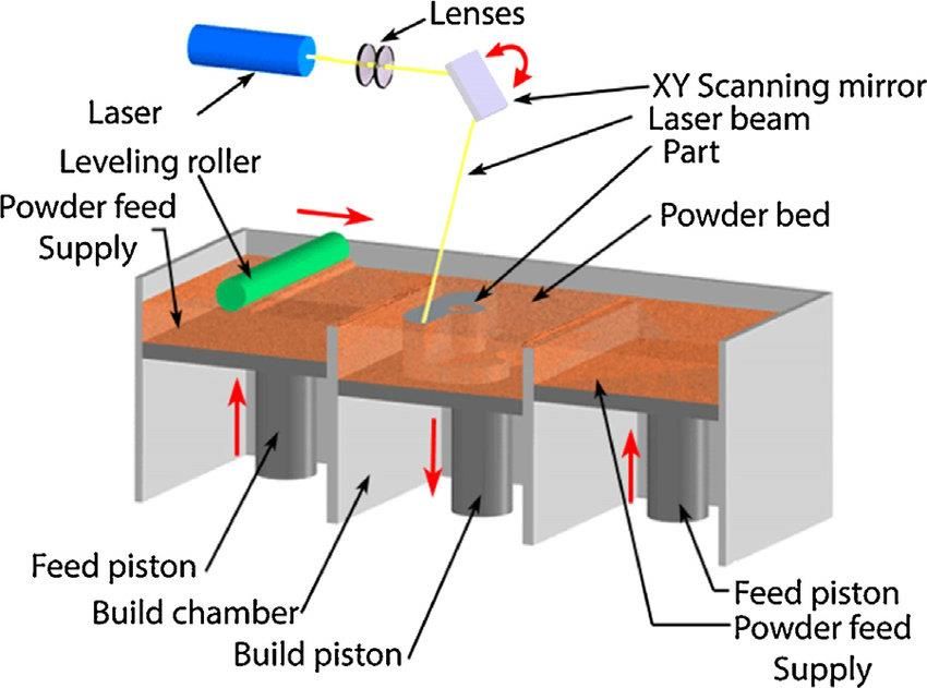
Materials 2021, 14, 3065                                                                                          3 of 35

                           2. Microstructural Evolution of HEAs Synthesized through the Melting and Casting Route
                                HEAs have been fabricated using the melting and casting route. Table 1 is a compila-
                           tion of some HEAs fabricated using the melting and casting route. In general, the melting
                           and casting route is a liquid-state processing route with equilibrium or non-equilibrium
                           cooling rates. An advantage of processing HEAs using the melting and casting route is
                           the high temperatures that can be realized or needed to melt some elements that make
                           up the HEA alloy [9]. Melting and casting can be achieved by a tilt casting furnace or
                           suction casting. During the melting and casting process, the phase transformation of
                           HEAs occurs during solidification (cooling). During solidification, phase evolution de-
                           pends on the collective mobility or distribution of constituent elements making up the
                           alloy [9]. However, the rate of cooling, differences in the local atomic arrangement, and
                           the varying elemental diffusivity can influence the solid phase that is first to form and the
                           microstructure of the alloys [24,25]. HEAs fabricated using the melting and casting route
                           usually show dendritic microstructures with interdendritic segregations. For instance,
                           AlCoCrFeNi HEAs fabricated using the melting and casting route have been shown to
                           exhibit BCC + B2 phases with dendritic microstructures [26,27]. Tian et al. [28] studied the
                           effect of different cooling rates using arc-melting processing routes in the fabrication of
                           AlCoCrFeNi HEAs. Both studies observed nanoparticles of the B2 phase within the grains
                           of the single-phase BCC structure. Lv et al. [29] compared the effect of cooling rates on the
                           microstructure of Alx CoCrFeNi HEAs using arc-melting and suction casting. The higher
                           cooling rate of the suction casting resulted in refined columnar dendrite grains, while the
                           arc-melting process led to a columnar cellular structure (see Figure 1). However, both
                           processes led to the formation of BCC and FCC phases, with the inclusion of a B2 phase for
                           arc-melting and Laves phases for suction casting. Thus, the melting and casting techniques
                           with faster cooling rates favor the formation of a more dominant single phase and limit
                           the precipitation of secondary phases [30]. Several studies have reported the cooling rate
                           effects on HEAs fabricated using melting and casting [25,31,32].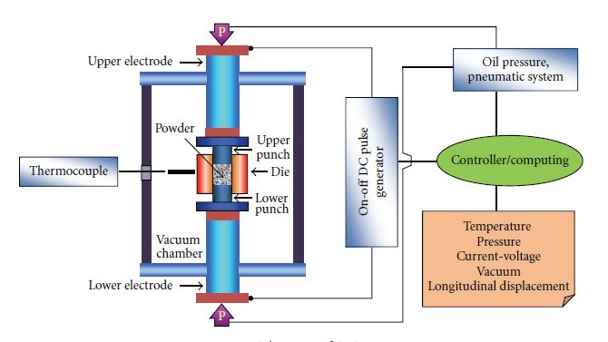
Materials 2021, 14, 3065                                                                                                                                                                 4 of 35

                                                        Table 1. Phase evolution of HEAs fabricated using the melting and casting route.

        HEA Composition                   Processing Method                 Observed Phase(s)                                 Microstructures and Comments                          Reference
            AlCoCrFeNi                       Arc-melting                           BCC                                       A dendritic structure is included.                      [26,28]
                                                                      Single phase consisting of a B2
              AlTiVCr                        Arc-melting                                                        The B2 phase is more stable than the disordered BCC phase.            [33]
                                                                     phase and a disordered BCC phase
            AlCoFeNiTi                       Arc-melting                           BCC                                       A dendritic structure is included.                       [34]
            TiVZrNbHf                        Arc-melting                     Single-phase BCC                                                                                         [35]
                                                                                                             The BCC phase is FeCrMo-rich, while the B2 phase is a NiAl-rich
          AlCrFeNiMo0.2                    Vacuum Induction                BCC and B2 structure                                                                                       [36]
                                                                                                                                intermetallic compound.
         NbCrMoTiAl0.5                                                                                                      Mo segregates to the dendritic region.
                                             Arc-melting                        Simple BCC                                                                                            [37]
       NbCrMoTiVAl0.5 Si0.3                                                                                       Cr, Ti, Al, and Si segregate to the interdendritic regions.
      Alx CoFeNiSi (x > 0.3)                 Arc-melting                           BCC                                                                                                [38]
                                                                                                           Dendritic and interdendritic regions are present due to constitutional
            MoNbTaVW                         Arc-melting                        Single BCC                                                                                           [39,40]
                                                                                                                             segregation during solidification.
         Alx CrFeMnNi0.5
                                             Arc-melting                           BCC                                                                                                [41]
           (x = 0.8–1.2)
        Nb25 Mo25 Ta25 W25                   Arc-melting                        BCC phase                                    There is no dendritic segregation.                       [15]
                                                                                                                        The matrix phase (BCC) is rich in Fe and Cr.
      Fe36 Mn21 Cr18 Ni15 Al10               Arc-melting                  Dual-phase 2 BCCs/B2                                                                                        [42]
                                                                                                                            The B2 phase is rich in Ni and Al.
                                                                                                         The interface morphology would grow in planar, cellular, and dendrite if
           CoCrCuFeNi                        Arc-melting                           FCC                                                                                               [18,43]
                                                                                                                           the solidification rate is increased.
         CoCrFeNiV0.5 Cx                                                                                    A large number of M7 C3 -type interstitial carbides are formed at an
                                             Arc-melting                           FCC                                                                                                [44]
  (x = 0.01, 0.02, 0.03, and 0.04)                                                                                    annealing temperature of 700 ◦ C and above.
        Fe40 Mn40 Co10 Cr10                Vacuum induction                        FCC                                                                                                [45]
                                                                                                             Precipitates of M23 C6 and the σ phase exist following prolonged
           CrMnFeCoNi                Arc-melting, Vacuum Induction                 FCC                                                                                               [11,46]
                                                                                                                                    exposure at 700 ◦ C.
           Alx CoCrFeNi                                                                                   The FCC phase is transformed to the BCC phase with the presence of a
                                             Arc-melting                           FCC                                                                                                [47]
            (x = 0–0.65)                                                                                          transition duplex FCC/BCC region as Al increases.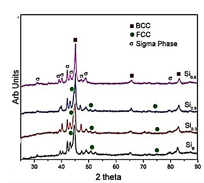
Materials 2021, 14, 3065                                                                                                                                                      5 of 35

                                                                        Table 1. Cont.

        HEA Composition                 Processing Method   Observed Phase(s)                                 Microstructures and Comments                               Reference
                                                                                         A crystalline structure is present consisting of a mixture of a (Ni, Ti)-rich
           CoCrFeNiTi0.3                   Arc-melting            FCC                                                                                                      [48]
                                                                                                R phase and a (Cr, Fe)-rich σ phase within the FCC matrix.
                                                                                           The BCC phase will evolve from the FCC phase with an increase in
       Al0.5 CoCrCu0.5 FeNi                Arc-melting            FCC                                              the Al content.                                         [49]
                                                                                                 FCC + BCC duplex phases will evolve at Al (0.5–1.5).
                                                                                         Lath-shaped FCC precipitates + nano-basket-weave microstructures are
         CoCrFeNiNb0.25                    Arc-melting            FCC                                                                                                      [50]
                                                                                                  randomly distributed in the proeutectic FCC phase.
         Alx CoCrFeNiTiy                   Arc-melting            FCC                      The Al and Ti content strongly affects the phase and microstructure.            [51]
     Co1.5 CrFeNi1.5 Ti0.5 Mox                                                            An interdendritic phase, (Ni, Ti)-rich phase and dendritic (Fe, Cr)-rich
                                           Arc-melting            FCC                                                                                                      [52]
            (x = 0, 0.1)                                                                                    phase are present when x = 0, 0.1.
 Mn22.3 Fe22.2 Ni22.2 Ge16.65 Si16.65      Arc-melting            FCC                          Magneto-structural first-order phase transition is exhibited.               [53]
           AlCrFeMnNi                      Arc-melting       BCC (B2) + FCC                        The BCC phase is interdendritic and rich in Al + Ni.                    [54]
                                                                                          Fine, regular, lamellar eutectic + coarse irregular eutectic hierarchical
    Ni30 Co30 Cr10 Fe10 Al18 W2            Arc-melting         FCC + BCC                                                                                                   [55]
                                                                                                                microstructures are present.
                                                                                            A dendritic region (higher Al and Cr) and an interdendritic region
         Al0.5 CrFeMnNi0.5                 Arc-melting         FCC + BCC                                               are present.                                        [56]
                                                                                                      Precipitates (AlNi B2 compound) are present.
           Alx CoCrFeNi
                                           Arc-melting         FCC + BCC                                    An AlNi-rich precipitate is formed.                            [57]
           (x = 0.45–0.85)
         Cr2 Cu2 FeNi2 Mn2
                                                                                                      A dendritic and interdendritic phase is present.
          Cr2 Cu2 NiMn2
                                           Arc-melting         FCC + BCC                                                                                                  [58,59]
          CrCu2 Fe2 NiMn                                                                  Cu, Mn, Cr, and Fe are segregated in dendritic/interdendritic regions,
          Cr2 CuFe2 NiMn                                                                          while Ni is homogeneously distributed in the alloy.
                                                                                         An increase in Al turns the dendritic structure to a lamella-like structure,
     Alx (CoCrFeMnNi)100−x                 Arc-melting         FCC + BCC                                                                                                   [60]
                                                                                                    hence the transit from the FCC to the BCC phase.
                                                                                                    Dendritic and interdendritic regions are present.
   CoCrFeMnNiZrx (x = 0–0.3)               Arc-melting         FCC + BCC                                                                                                   [61]
                                                                                          The interdendritic region increases with an increase in the Zr content.
Materials 2021, 14, 3065 6 of 35
Table 1. Cont.
HEA Composition Processing Method Observed Phase(s) Microstructures and Comments Reference
Dendritic (contains compound impurities) and chrysanthemum-shape
AlCoCrCux NiTi
Arc-melting FCC + BCC dendrites are present. [62]
(x = 0.5–0.8) Cu segregates in the interdendritic region.
FCC 1 is Cu rich, and FCC 2 is Co rich (x = 1/3, 3/7, and 3/5).
CoCuy FeNiTix Arc-melting 2 FCCs + BCC [63]
The BCC phase is β Ti rich (x = 3/5).
A cast-dendritic morphology is present.
CoCrFeNiCuAl Arc-melting FCC + BCC The BCC phase is an ordered one. [64,65]
of 2 FCC phases are present.
Fe50-X Mn30 Co10 Cr10 BX The addition of boron promotes the formation of M2 B-type borides
Arc-melting FCC + BCC [66]
(x = 0, 0.3, 0.6, 1.7 wt%) (M = Cr, Fe).
The 2BCC phase is formed by spinodal decomposition, i.e., B2 (NiAl
AlCrCuFeMnNi Vacuum Induction 2 BCCs (B2 + A2) + FCC [67]
dendrite matrix) and A2 (Cr-Fe rich) embedded precipitate.
The presence of the Al-Ni-rich phase decreases as the aging temperature
Al0.5 CoCrFeNi Arc-melting, Vacuum Induction FCC + BCC crystalline structures increases and, hence, leads to an increase in the amount of [68,69]
Al-(Ni, Co, Cr, Fe).
The HEA with “V” shows a dendritic/cellular microstructure rich in
BCC + HCP—with W inclusion
NbMoTaTi–(W, V) Arc-melting Ti and V. [70]
BCC—with V inclusion The HEA with “W” forms a Ti-rich HCP phase.
A dendrite rich in Cr and V is present.
Al0.5 CrCuNiV Arc-melting FCC + 2 BCCs + B2 [71]
The incorporation of Cu into the 2-BBC phase differentiates it from
the B2 phase.
AlCoCrFeNi2.1 Vacuum Induction Dual-phase FCC + BCC (B2) - [72]
AlCrCuFeNi
Arc-melting FCC + BCC The content of Ni has a significant effect on the HEA microstructure. [73,74]
(0.6 ≤ x ≤ 1.4)Materials2021,
Materials 2021,14,
14,3065
x FOR PEER REVIEW 9 7ofof3335
Figure1.1. OM
OM micrographs
micrographsofofarc-melting (AM
arc-melting x) and suction-casting (SCx) alloys (x = 0.15 and 0.5). (a) Columnar cellular
(AM
Figure x ) and suction-casting (SCx ) alloys (x = 0.15 and 0.5). (a) Columnar
structure and (c) non-equiaxed columnar dendrite by arc-melting; (b) and (d) columnar dendrite grains by suction casting
cellular structure and (c) non-equiaxed columnar dendrite by arc-melting; (b) and (d) columnar dendrite grains by
[29].
suction casting [29].
From another perspective, HEA phase formation during fabrication via the melting
From another perspective, HEA phase formation during fabrication via the melting
and casting route is suggested to hinge on binary constituent pairs rather than individual
and casting route is suggested to hinge on binary constituent pairs rather than individual
constituent elements [75,76]. An HEA system such as the AlCoCrFeNi alloy forms a BCC
constituent elements [75,76]. An HEA system such as the AlCoCrFeNi alloy forms a BCC
structure after processing; although among the constituent elements, only Cr and Fe have
structure after processing; although among the constituent elements, only Cr and Fe have
BCC crystal structures. The AlNi pair, from the possible binaries in the AlCoCrFeNi sys-
BCC crystal structures. The AlNi pair, from the possible binaries in the AlCoCrFeNi system,
tem, serves as the primary crystal structure in the AlCoCrFeNi HEA. This is due to the
serves as the primary crystal structure in the AlCoCrFeNi HEA. This is due to the similar
similar lattice parameter between AlNi (0.28810 nm) and AlCoCrFeNi (0.289675 nm)
lattice parameter between AlNi (0.28810 nm) and AlCoCrFeNi (0.289675 nm) [77,78]. In
[77,78]. In addition, AlNi has the largest negative enthalpy of formation among all the
addition, AlNi has the largest negative enthalpy of formation among all the binary pairs in
binary pairs in AlCoCrFeNi [79–81]. The AlNi binary pair stabilizes over a wide compo-
AlCoCrFeNi [79–81]. The AlNi binary pair stabilizes over a wide composition field from
sition field from 1638 °C down to room temperature and can dissolve other constituent
1638 ◦ C down to room temperature and can dissolve other constituent elements [82,83].
elements [82,83]. The other elements, therefore, dissolve into the primary lattice due to
The other elements, therefore, dissolve into the primary lattice due to their chemical
their chemical compatibility and mixing entropy effect [84]. During solidification, Cr hav-
compatibility and mixing entropy effect [84]. During solidification, Cr having the highest
ing the highest melting point is the first element to solidify. Cr remains segregated from
melting point is the first element to solidify. Cr remains segregated from the liquid mixture
the liquid mixture up to 1350 °C at the equiatomic composition [85,86]. In contrast, Al has
up to 1350 ◦ C at the equiatomic composition [85,86]. In contrast, Al has the lowest melting
the lowest melting temperature and thus has the highest diffusivity during solidification.
temperature and thus has the highest diffusivity during solidification. The effect of Al
The effect of Al addition on 3d transition metal-based HEAs such as AlCoCrFeNi been
addition on 3d transition metal-based HEAs such as AlCoCrFeNi been studied [87–89].
studied [87–89]. The increasing quantity of Al promotes the formation of the BCC phase
The increasing quantity of Al promotes the formation of the BCC phase [89–91]. Moreover,
[89–91]. Moreover, Wang et al. [92] and Rogström et al. [93] observed that the AlCoCrFeNi
Wang et al. [92] and Rogström et al. [93] observed that the AlCoCrFeNi HEA exhibits a
HEA exhibits a spinodal microstructure of an A2 ((Cr, Fe)-rich) disordered solid solution
spinodal microstructure of an A2 ((Cr, Fe)-rich) disordered solid solution and a modulatedMaterials 2021, 14, 3065 8 of 35
B2 ((Al, Ni)-rich) ordered solid solution. The A2 phase forms at temperatures below 600 ◦ C,
while the B2 phase forms at higher temperatures [92].
Some examples of HEAs that exhibit a single-phase FCC structure after melting
and casting are the CoCrFeMnNi HEA structure [14,94], the Alx CoCrCuFeNi alloy sys-
tem [95,96], the CoCrCuFeNi HEA [97,98], the FeCoNiCrCuO0.5 Alx HEA [49], and the
Alx CoCrFeNiTiy HEA [51,99]. The binary constituents in these HEAs encourage the forma-
tion of the FCC phase. In addition, the addition of elements such as Cu and Ti stabilizes
the FCC phase [100,101]. In the Alx CoCrFeNi alloy system, the addition of Ti promotes
phase evolution from the BCC to an FCC phase [81]. Furthermore, when Al in AlCoCrFeNi
is replaced with Cu to form the CoCrCuFeNi alloy, the FCC phase forms instead of an
A2 + B2 structure associated with AlCoCrFeNi. CuCo, CuNi, CoNi, FeNi, and CoFe, which
make up the binary constituents in the CoCrCuFeNi alloy, all have an FCC structure and
promote the FCC phase. In addition, the use of Mn to form CoCrFeMnNi also leads to a
single-phase FCC structure [102].
3. Powder Metallurgy
3.1. Mechanical Alloying (MA)
MA is a solid-state process that allows the dispersion of insoluble phases and the
addition of reactive alloying elements to produce composite metal powders with controlled
microstructures. In this process, a high-energy stirred ball mill or shaker mill is used to
subject blended powders of known particle size to a compressive force to agglomerate
the powders. The mechanical alloying process can be grouped into five different stages:
the initial stage, a period of welding, an equiaxed particle formation period, the start of
random welding orientation, and steady-state processing [103]. Hence, these periods can
be explained in terms of [103] (a) the distribution of the powder and shape, (b) how hard
the material is on the ball surface, (c) the microstructure of the powder and material on
the ball surface, and (d) the material division between ball surfaces and free powders. The
formation of composite particles and the refinement of structure occur over time as a result
of repeated welding and fracturing of free powder particles.
MA has been given more preference in the literature recently compared to conven-
tional methods such as melting and casting. It does aid the homogeneous distribution of
particle size, consolidation, and a reduction in grain size and helps in proper densification
of elemental powders [104]. The mechanical energy input as well as the rate of work
hardening among the material influences the rate of structural refinement in HEAs. These
thus have a positive effect on the resulting mechanical properties of HEAs. Hence, the
MA technique is considered a more convenient and cost-effective way of synthesizing
nano-crystalline materials with a uniform microstructure [104].
3.2. Spark Plasma Sintering (SPS)
SPS uses a direct current (DC) pulse voltage and current during compaction of as-
milled alloy powders to produce a bulk alloy in the solid state [105]. Spark plasma
and spark impact pressure are used to generate high temperatures between the parti-
cles, causing melting of the surface of the particles during the sintering process [106].
Chakraborty et al. [107] classified the mechanism of sintering of a bulk alloy using SPS into
five stages: generation of plasma, heating, melting, sputtering of the molten particles, and
neck growth. The as-milled powder is directly charged into a graphite die through which
current and uniaxial force or pressure are applied simultaneously, resulting in a fully dense
material with outstanding mechanical properties [108]. Densification is achieved for both
conductive and nonconductive powders in a short time due to the fast heating rate [106].
Application of high heating and cooling rates in SPS enhances densification and promotes
the diffusion mechanism, which helps to maintain the powders’ intrinsic properties in
a fully dense state [108]. A higher cooling rate reduces the level of micro-segregation in
the alloy and leads to refinement of grain size, which is achievable in SPS [109]. Hence,
the need for heat-treating SPS-fabricated HEAs might be unnecessary. This is in contrastneed for heat-treating SPS-fabricated HEAs might be unnecessary. This is in contrast
the as-cast microstructure having the possibility of generating a dendritic microstru
during the solidification process [8]. Therefore, SPS present tremendous potential an
Materials 2021, 14, 3065 sinter a fully dense and nearly single-phase alloy with a refined microstructure 9 of 35 from
mental powder. The microstructure and phases in the final sintered products are si
cantly influenced by the processing parameters.
withSPS
The the as-cast
method microstructure
is widelyhaving
used,the possibilityto
especially of synthesize
generating a dendritic microstruc- micro
nano-crystalline
ture during the solidification process [8]. Therefore, SPS present tremendous potential
tures,and
advanced ceramics, and composite materials, owing to its advantages over co
can sinter a fully dense and nearly single-phase alloy with a refined microstructure
tionalfrom
sintering
elementaltechniques
powder. The[110]. The sintering
microstructure system
and phases not sintered
in the final only offers ease
products areof oper
but also results in less grain growth in the microstructure. Hence, this leads to a
significantly influenced by the processing parameters.
The SPS method is further
proved microstructure, widely used, especially
leading to synthesize
to better nano-crystalline
resulting mechanical microstruc-
properties
tures, advanced ceramics, and composite materials, owing to its advantages over conven-
compared to the techniques
tional sintering melting [110].
and Thecasting route.
sintering system Solid solution
not only offers easestrengthening
of operation but is ach
through
alsothis fabrication
results in less graintechnique,
growth in thewhich also has
microstructure. a positive
Hence, this leadsimpact on the mecha
to an improved
microstructure, further leading to better resulting mechanical properties
properties of HEAs. These are some of the reasons many researchers lately prefer S when compared
to the melting and casting route. Solid solution strengthening is achieved through this
a mode of compacting powders, in addition to its significant advantages such as sh
fabrication technique, which also has a positive impact on the mechanical properties of
processing
HEAs. timeThese[110], flexible
are some sintering
of the reasons manytemperature, avoidance
researchers lately prefer SPS ofasporosity,
a mode of easy co
of sintering
compactingparameters,
powders, inand energy-efficient
addition to its significantprocessing.
advantages such Figure 2 shows
as shorter a schemati
processing
time [110], flexible
gram of the SPS process. sintering temperature, avoidance of porosity, easy control of sintering
parameters, and energy-efficient processing. Figure 2 shows a schematic diagram of the
SPS process.
Figure 2. Schematic diagram of the SPS process [108].
Figure 2. Schematic diagram of the SPS process [108].
3.3. Microstructural Evolution of HEAs Synthesized Using Powder Metallurgy
The PM synthesis
3.3. Microstructural route through
Evolution of HEAsMA and consolidation
Synthesized Usingby SPS hasMetallurgy
Powder been used in the
fabrication of HEAs [10,111,112]. The MA and SPS techniques are solid-state processing
The PM
routes synthesis
mostly used toroute through
achieve MA and
nanocrystalline consolidation
HEAs [113]. The MAbyprocess
SPS hasis abeen
non- used
equilibrium process and thus leads to the formation of metastable phases.
fabrication of HEAs [10,111,112]. The MA and SPS techniques are solid-state Table 2 shows a proce
summary of evolved phases of some HEAs fabricated through MA and SPS.
routes mostly used to achieve nanocrystalline HEAs [113]. The MA process is a non-
librium process and thus leads to the formation of metastable phases. Table 2 sho
summary of evolved phases of some HEAs fabricated through MA and SPS.Materials 2021, 14, 3065 10 of 35
Table 2. Phase evolution of HEAs after MA and SPS.
Phase Evolution
HEA Alloy MA Parameters SPS Parameters Reference
MA After SPS
S = 300 rpm ST = 600 ◦ C (4 min)
BPR = 10:1 HR = 75 ◦ C min−1
FeNiCrCo0.3 Al0.7 ST = 600 to 1000 ◦ C (at HR = 50 ◦ C min−1 in [114]
D = 45 h BCC BCC + FCC
4 min)
GM = stainless steel vial, tungsten (1000 ◦ C in 8 min),
carbide balls P = 30 MPa
S = 250 rpm
ST = 900 ◦ C (10 min)
BPR = 15:1
CoCrFeNiAl D = 60 h P = 50 MPa BCC after first 30 h of MA BCC + FCC [112]
Annealed from 500–1000 ◦ C for 1 h ◦C
Cooled to 600 in 5 min
GM = stainless steel vial and balls
ST = 570–800 ◦ C
S = 300 rpm
HR = 100 ◦ C min−1
AlCoCrFeNiSix (x = 0.3, BPR = 10:1 ST = 800 ◦ C–1000 ◦ C
BCC BCC + FCC + sigma phase [115]
0.6, and 0.9) D = 20 h HR = 50 ◦ C min−1
(1000 ◦ C in 5 min),
GM = tungsten carbide vial
P = 60 MPa
S = 300 rpm
ST = 1000 ◦ C (10 min)
Al0.4 FeCrCo1.5 NiTi0.3 BPR = 10:1 BCC + FCC FCC (major) + BCC (minor) [116]
D = 50 h (dry) + 5 h (wet) P = 30 MPa
S = 300 rpm ST = 600 ◦ C (4 min)
ST = 600–900 ◦ C
BPR = 10:1
HR = 75 ◦ C min−1
BCC + FCC within first
Al0.5 CrFeNiCo0.3 C0.2 ST = 900–1000 ◦ C FCC (major) + BCC [117]
D = 38 h dry + 4 h wet (42 h) 38 h MA
HR = 50 ◦ C min−1
GM = stainless steel vial, tungsten (1000 ◦ C in 8 min)
carbide balls P = 30 MPaMaterials 2021, 14, 3065 11 of 35
Table 2. Cont.
Phase Evolution
HEA Alloy MA Parameters SPS Parameters Reference
MA After SPS
S = 250 rpm
ST = 800 ◦ C (10 min)
BPR = 15:1
D = 60 h
CoCrFeNiMnAl BCC BCC + FCC [118]
Annealed from 500–1000 ◦ C P = 50 MPa
GM = stainless steel vial and balls,
N-heptane PCA
S = 250 rpm ST = 1000 ◦ C at HR = 100 ◦ C min−1
BPR = 10:1 ST = 1000–1100 ◦ C at HR = 50 ◦ C min−1
Ni1.5 Co1.5 CrFeTi0.5 D = 30 h dry + 2 h wet (toluene) (32 h) ST = 1100–1150 ◦ C at HR = 20 ◦ C min−1 BCC + 2 FCCs FCC + oxide [119]
GM = hardened tool steel vial and (1150 ◦ C in 20 min)
hardened balls P = 30 MPa
S = 580 rpm
ST = 700, 800, and 900 ◦ C (15 min)
BPR = 1:10
B2 + FCC + (Fe,Cr)23 C6
AlCuNiFeCr D=5h BCC [120]
P = 150 MPa after SPS
GM = hardened ShH-15 steel, gasoline
medium
S = 400 rpm
Nb25 Mo25 Ta25 W25 ST = 1600 ◦ C (8 min)
BPR = 15:1
BCC BCC [121]
D = 60 h
P = 35 MPa
Ti8 Nb23 Mo23 Ta23 W23 GM = tungsten carbide vials, acetone
PCA
S = 300 rpm
ST = 1000 ◦ C (8 min)
BPR = 10:1
BCC (B2) + FCC + Al3 Ti
CoNiFeAlTi D = 4 h wet + 45 h dry (49 h) HR = 90 ◦ C min−1 BCC + FCC [122]
intermetallics after SPS
GM = stainless steel vials and tungsten
P = 30 MPa
carbide balls, no PCAMaterials 2021, 14, 3065 12 of 35
Table 2. Cont.
Phase Evolution
HEA Alloy MA Parameters SPS Parameters Reference
MA After SPS
S = 200 rpm ST = 800, 900, and 1000 ◦ C (10 min),
BPR = 15:1
Al0.3 CoCrFeMnNi D = 36 h HR = 100 ◦ C min−1 BCC (B2) after SPS [123]
FCC
GM = stainless steel vials and balls,
P = 50 MPa
N-heptane PCA
S = 200 rpm
ST = 800, 900, and 1000 ◦ C
(CuCrFeTiZn)100-x Pbx BPR = 20:1
Fe-Cr (BCC) + Cu-Zn (FCC) Fe-Cr (BCC) + Cu-Zn (FCC) [124]
(x = 0, 5, 10, and 20) D = 44 h HR = 150 ◦ C min−1
GM = tungsten carbide vials and balls P = 50 MPa
Legend: S, milling speed; BPR, ball-to-powder ratio; D, milling duration; ST, sintering temperature; HR, heating rate; P, compression pressure; GM, grinding media.Materials 2021, 14, 3065 13 of 35
The binary-phase diagrams of constituent elements and the thermodynamic concept
of mixing enthalpies in an HEA system help understand or predict possible phases during
MA [125]. The energy involved during the MA process generates heat and influences the
phases that form. Typically, an alloy system would tend toward phases for which free
energy is the lowest. So, for the desired phase(s), it is imperative to achieve the right balance
of parameters used in the MA process, such as milling duration, ball-to-powder ratio (BPR),
and the grinding media. Chen et al. [114] studied the alloying behavior, microstructure,
and mechanical properties of FeNiCrCo0.3 Al0.7 HEA fabricated using the MA and SPS
route. The FeNiCrCo0.3 Al0.7 HEA formed a refined and homogeneous supersaturated
BCC solid solution after 45 h of milling. After the first 6 h of milling, Al and Co rapidly
dissolved into the solution compared to the other elements, as depicted in Figure 3. Even
though Al and Co quantities were less, their rapid diffusion could be attributed to their
relatively low melting temperatures.
Figure 3. XRD pattern of FeNiCrCo0.3 Al0.7 with different milling times [114].
Other elements such as Cr and Fe dissolved into solution as the milling time increased.
Cr and Fe exhibit a BCC crystal structure and therefore may accommodate other elements
without much expansion [114,126]. Additionally, Cr has the highest melting temperature
in the HEA system and thus diffuses the slowest during the MA process. The MA process
is known to include repeated welding and fracturing, leading to crystallite refinement.
Since HEAs are baseless systems composed of elements with different atomic sizes, the
size mismatch effect occurs during the MA process. Increasing milling time during the
MA process leads to an increase in dislocation density and lattice strain caused by the
severe plastic deformation occurring, and the size mismatch effect and increase in the grain
boundary fraction owing to the crystallite refinement [127].
Vaidya et al. [81] studied the effect of the elemental addition sequence on the phase
evolution of the nanocrystalline AlCoCrFeNi HEA system using the MA processing tech-
nique. Three different classes of binaries were selected as initial starting phases, while other
constituent elements were added stepwise in varying sequences until quinary systems
were formed. The binaries included B2 (AlNi, AlCo and AlFe), BCC (FeCr), and FCC
(CoNi and FeNi) phases. For example, in AlCo starting as a binary lattice, the more the
FCC phase from the dual BCC + FCC phase expands, the more Al dissolves into the solid
solution. The addition of Ni to AlCo (B2) favors an FCC structure instead of a stabilizing
B2
1 structure. This indicates a high tendency of an FCC solid solution of Ni (Co) forming
than an intermetallic AlNiCo phase. The formation of AlCoNiFeCr from AlCoNi due to
the addition of Fe and Cr destabilizes the FCC phase. As a result, the BCC phase evolves
from FCC to form BCC (major) + FCC as the final microstructure. Praveen et al. [128]
also reported a similar phase during MA of CoCrFeNi alloy. There were variations in theMaterials 2021, 14, 3065 14 of 35
amount of BCC and FCC present at the end of each sequence in the CoCrFeNi HEA fabri-
cated. The resulting microstructure of AlCoNiFeCr HEA, BCC + FCC, remained consistent
with a wide range of sequences despite variation in both alloying sequence and milling
duration. This is contrary to the single-phase BCC formation reported when FeNiCoCrAl,
FeCrAlNiCo, AlNiCoFeCr alloy sequences from three different binaries were processed
using arc-melting [129,130]. In addition, the base alloy sequence AlCoCrFeNi exhibited a
single-phase BCC structure when fabricated using arc-melting [129].
It is noteworthy that the alloy sequences starting with the BCC phase showed a larger
amount of FCC phase fractions at the end of milling, and this phase becomes stable when
nanocrystalline Ni is added. Therefore, it can be inferred that the FCC phase is promoted
by Ni and Co addition, unless when Co is added immediately after Al owing to Co’s strong
affinity to Al. The BCC phase is stabilized by the addition of Al during sequential alloying
irrespective of the position at which it is added [20,120]. Cr favors BCC phase formation,
while Fe has the least influence on phase formation due to a less negative ∆Havg and the
lowest atomic radius. It can be deduced that the initial structure of the binary alloy, the
addition of individual elements, and the order of mixing constituents are some of the
factors that influence the phase evolution during sequential alloying in the MA route.
Furthermore, the formation of the supersaturated BCC solid solution in the
FeNiCrCo0.3 Al0.7 HEA is attributed to the energy stored in the grain boundaries, high
entropy of mixing, and solid solubility extension [114,131]. Partial BCC phases in the
FeNiCrCo0.3 Al0.7 HEA after MA evolved to a more stable FCC phase during the SPS
process at 1000 ◦ C. The annihilation of defects introduced into the structure owing to the
high-energy ball milling during the MA process leads to reordering at high temperatures.
As a result, defects introduced by severe plastic deformation during MA are nearly anni-
hilated after consolidation by SPS, which can also contribute to phase evolution during
SPS. Ji et al. [112] obtained a BCC solid solution for CoCrFeNiAl HEA after milling for 60 h.
From the study, the BCC solid solution formed during the first 30 h and was only refined
as milling progressed to 60 h. After SPS consolidation at 900 ◦ C, BCC and FCC phases
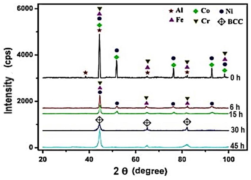
formed. Kumar et al. [115] also achieved a BCC supersaturated solid solution by MA of
AlCoCrFeNiSix for 20 h. The studied alloy was quite similar to that of Ji et al. However,
a BCC solid solution was attained after a shorter milling duration (20 h) compared to
the 60 h done by Ji et al. [112]. This goes to show that milling speed also influences the
phases formed during the MA process. Kumar et al. [115] used a milling speed of 300 rpm,
while Ji et al. [112] used a speed of 250 rpm. Major phases composed of BCC, FCC, and
sigma were obtained in the AlCoCrFeNiSix (x = 0.3, 0.6, and 0.9) fabricated by MA after
SPS consolidation at 1000 ◦ C. However, only BCC and sigma phases were observed in
AlCCrFeNiSi0.9 . Figure 4 shows the XRD pattern of AlCoCrFeNiSix after SPS. Si is known
to be a BCC former and stabilizer. Si, having the ability to occupy another element spot
in the grain boundary, shows that more atoms will be replaced with an increase in the Si
content [115]. This, thereby, introduced lattice distortion and lattice strain in the system,
while it destabilized the FCC phase.Materials 2021, 14, 3065 15 of 35
Materials 2021, 14, x FOR PEER REVIEW 17 of 33
Figure4.4.XRD
Figure XRDpattern
patternof
ofAlCoCrFeNiSi
AlCoCrFeNiSixafter
afterSPS,
SPS,where
wherexx== 0,
0, 0.3,
0.3, 0.6,
0.6,and
and0.9
0.9[115].
[115].
x
4.4.Microstructural
MicrostructuralEvolution
Evolutionof
ofHEAs
HEAsFabricated
Fabricatedby
byAdditive
AdditiveManufacturing
Manufacturing(AM)
(AM)
AM
AMhashasbecome
becomeaamainstream
mainstreammanufacturing
manufacturingprocessprocessbecause
becauseof ofits
itsflexible
flexibledesign
design
optimization
optimization and
andprocessing
processingadvantages.
advantages. TheThe production
production of ofcustomized
customizedpartspartsand
andthethe
ability
abilityto
tocontrol
controlthe
themicrostructure
microstructurein inaaspecific
specificsite
siteare
arepossible
possiblein inthis
thisprocessing
processingroute.
route.
The
Thehigher
higherheating
heating and
and cooling rates associated
associated with
withAM AMpromote
promotechemical
chemicalhomogeneity
homogene-
ity in alloys by restricting diffusion to avoid undesired multiple phase transformations
in alloys by restricting diffusion to avoid undesired multiple phase transformations dur-
during cooling
ing cooling [132].
[132]. Solidification
Solidification mainly
mainly takes
takes place
place along
along the the building
building direction
direction andand is
is pre-
predominantly epitaxial.
dominantly epitaxial. Thesuccessive
The successivebuilding
buildingprocess
processin in thin
thin layers
layers by
by local
local heat
heatinput
input
characterizes
characterizesthe
themicrostructures
microstructuresasasaaresult
resultofofrapid
rapidand
anddirectional
directionalsolidification.
solidification.Factors
Factors
such
such as powder flowability, laser power, powder thickness and shape, scan spacing,and
as powder flowability, laser power, powder thickness and shape, scan spacing, and
volumetric
volumetricenergy
energydensity
density(VED)
(VED)allallplay
playananimportant
importantroleroleinindetermining
determiningthe theresulting
resulting
microstructure
microstructurein inAMAMtechnology.
technology.Figure
Figure55below
belowshowsshowsthetheschematic
schematicrepresentation
representationofof
additive manufacturing techniques.
additive manufacturing techniques.
2
Figure5.5.Schematic
Figure Schematicrepresentation
representationofofadditive
additivemanufacturing
manufacturingtechniques
techniques[133].
[133].
Table 3 presents some HEAs fabricated using the AM route. The AlCrFeCoNi HEA
system has also been synthesized by Kuwabara et al. [134] and Fujieda et al. [135] usingMaterials 2021, 14, 3065 16 of 35
Table 3 presents some HEAs fabricated using the AM route. The AlCrFeCoNi HEA
system has also been synthesized by Kuwabara et al. [134] and Fujieda et al. [135] using the
selective electron beam melting (SEBM) AM technique. The microstructure of the SEBM
HEA exhibited a BCC and a B2 phase, same as that reported when processed through
the melting and casting route, despite the rapid solidification of the SEBM process [16,28].
In addition to the BCC microstructure, an FCC phase was observed at the bottom of the
SEBM-fabricated HEA. The precipitation of the FCC phase could have resulted from the
BCC or B2 phase in a lower temperature range during building. Moreover, the phase
evolution could have also occurred during the preheating process, which is associated
with the SEBM AM technology. The coexistence of BCC and FCC phases in AlCrFeCoNi
was confirmed when Ji et al. [112] fabricated the same HEA using the powder metallurgy
(MA + SPS) approach.
Jung et al. [136] fabricated an AlCrFeCoMnNi HEA using the laser powder bed fusion
(LPBF) process. Again, the microstructure revealed B2 (Ni-Al-rich) and BCC (Fe-Cr-rich)
solid solutions. This is in contrast with the formation of BCC and FCC phases achieved in
the same alloy when synthesized using either powder metallurgy or the melting and casting
process [60,118]. The microstructure formation of the AlCrFeCoMnNi HEA fabricated by
LPBF was attributed to (1) liquid-phase spinodal decomposition from an undercooled
melting, (2) the cubic nature of the HEA and the highly textured microstructure associated
with LPBF, and (3) properties of alloying elements, such as Mn, Al, and Zn volatility at
high temperature. Depletion of such elements at the melt pool surface leads to a reduction
in the distribution of elemental composition across different layers. For instance, depletion
of Al in the AlCrFeCoMnNi HEA results in variation in the Al content across built layers,
which leads to a variation in the phase transition temperatures and the phase composition.
Fine BCC grains were found distributed at the grain boundaries of the FCC matrix
when Gao et al. [137] fabricated a CoCrFeMnNi HEA using laser 3D printing technology.
This is in contrast with the single-phase FCC achieved by Kucza et al. [14] Tsai, et al. [92],
Pickering et al. [11], and Yao et al. [46], who that processed the same HEA using different
forms of melting and casting routes. Joo et al. [138] also confirmed the presence of single-
phase FCC in CoCrFeMnNi when fabricated using the powder metallurgy technique. FCC
(major) matrix grain boundaries were partially wetted by a BCC solid second phase in the
printed HEA. Grain boundary wetting phase transformation is known to be responsible
for the morphology of the second solid phase in the grain boundaries of the first solid
phase. Al0.3 CoCrFeNi exhibited single-phase FCC when processed through LPBF [139]. A
similar alloy was fabricated using the melting and casting route, yet it showed the same
microstructure [47]. However, rapid solidification and anisotropic heat removal associated
with LPBF generate fine columnar grains in the HEA. This factor seems to not influence the
Al0.3 CoCrFeNi microstructure in this case. There is consistency in the microstructure of
AlCoCrFeNiTi0.5 when fabricated using both laser-engineered net shaping (LENS) [140] as
well as the melting and casting route [141]. The microstructure exhibited both disordered
and ordered BCC phases. However, Shaofeng et al. [116] reported a mixture of BCC and
FCC in the same alloy when fabricated using MA + SPS. A laser-engineered net-shaping-
processed AlCoCrFeNiTi0.5 HEA contains a fully equiaxed grain microstructure rather
than a columnar microstructure mostly associated with alloys fabricated by AM [142–144].
Hence, an AlCoCrFeNiTi0.5 HEA defies the norms in this regard. Luo et al. [145] reported
a BCC solid solution in a selective laser-melting-processed AlCrCuFeNi HEA. However,
Jinhong et al. [73] and Anmin et al. [74] reported the presence of FCC and BCC in the
same as-cast alloy. The presence of FCC and BCC phases was also confirmed in the same
HEA using the powder metallurgy approach [120]. The FCC phase formation might have
been inhibited as a result of rapid cooling during the selective laser melting fabrication
process [73]. In this fabrication process, the high lattice distortion and elastic strain induced
in the HEA is a result of the rapid cooling.Materials 2021, 14, 3065 17 of 35
Table 3. Phase evolution of HEAs fabricated using different additive manufacturing routes.
HEA Composition Processing Method Observed Phase(s) Microstructures and Comments Reference
An equiaxed-to-columnar transition structure was discovered
CoCrFeMnNi Laser 3D printing FCC (major) + BCC [137]
in the melt pool.
Nanotwins were present in the printed sample.
CoCrFeMnNi Laser powder bed fusion (LPBF) FCC + σ phase Mn segregates at the boundary of the weld pool due to [146]
its volatility.
No phase transformation occurred
CoCrFeMnNi Laser directed energy deposition FCC solid solution [147]
Lattice strain and grain refinement occurred.
AlCrFeCoNi Selective electron beam melting (SEBM) FCC + BCC Phase evolution occurred during the preheating process [134,135]
B2 (Ni-Al rich) and A2 (Fe-Cr rich)
AlCrFeCoMnNi LPBF BCC (B2, A2) Due to liquid-phase spinodal decomposition and cubic nature [136]
of the HEA
Fine columnar grains were present due to rapid solidification
Al0.3 CoCrFeNi LPBF Supersaturated FCC phase [139]
and anisotropic heat removal.
A fully equiaxed grain microstructure was exhibited rather
AlCoCrFeNiTi0.5 Laser-engineered net shaping (LENS) 2 BCC (B2, A2) than a columnar microstructure associated with alloys [140]
fabricated with AM.
Unique columnar grains were present containing multiple
AlCrCuFeNi LPBF 2 BCC (B2, A2) [145]
ultrafine sub-grain structures.
Rapid cooling rate and solidification resulted in the formation
AlCrFeNiV LPBF FCC [148]
of sub-grains in every columnar grain and L12 nano-phase.
Columnar BCC of spinodal decomposed B2 and A2 structures
AlCrFe2 Ni2 LPBF BCC was exhibited. [149]
Cracks were present at the intergranular site.
After annealing at 1373 K, columnar grains and equiaxial
FeCoCrNi LPBF FCC [150]
grains were found to co-exist.Materials 2021, 14, 3065 18 of 35
Table 3. Cont.
HEA Composition Processing Method Observed Phase(s) Microstructures and Comments Reference
Intergranular needle-like and plate-like FCC phase
precipitates and wall-shaped FCC phase precipitates were
AlCoCrFeNi Direct laser fabrication (DLF) BCC (B2) [151]
present along grain boundaries after aging at 800, 1000,
and 1200 ◦ C.
MoNbTaW Direct energy deposition (DED) BCC [152]
Two phases were present: TaMoNbCr and (TaMoNbCr)Al
Al0.5 Cr1.0 Mo1.0 Nb1.0 Ta0.5 SEBM BCC [153]
solid solutions.
Dendritic grains were present.
CoCrCuFeNiAl LENS BCC (B2, A2) [154,155]
An ordered interface transition region was present between
the two phases.
Co, Cr, and Fe stabilize L12 .
AlCoCrFeNi2.1 LENS Ordered FCC (L12 ) + BCC [156]
L12 and BCC are rich in nickel.
Deformation-induced phase transformation of γ (FCC) to ε
Fe38.5 Mn20 Co20 Cr15 Si5 Cu1.5 LPBF FCC [157]
(HCP) occurred in the vicinity of microcracks.
There was complex structural evolution, from loosely packed
CoCrFeNi 3D extrusion printing FCC oxide particles in the green body to fully-annealed, [158]
metallic CoCrFeNi.
The high solubility of V offers a broad range of solid solution
AlCrFeMoVx (x = 0 to 1) LENS BCC strengthening of a compositionally complex but structurally [158]
simple BC matrix.
C14 Laves phase (major) + α-Ti The C14 Laves phase becomes stable on exposure to annealing
ZrTiVCrFeNi LENS [159]
solid solution and hydrogen influence.
Equiaxed polygonal grains, discontinuous interdendritic
6FeNiCoSiCrAlTi Laser cladding BCC [160]
segregation, and nano-precipitates are present.Materials 2021, 14, 3065 19 of 35
Table 3. Cont.
HEA Composition Processing Method Observed Phase(s) Microstructures and Comments Reference
Cellular crystals are formed on which dispersion
MoFeCrTiW Laser cladding BCC [161]
precipitates exist.
FCC (δTiHx -type) + BCC αZr-rich precipitates are present, in addition to the
TiZrNbMoV LENS [162]
(NbH∼ 0.4 –type) phases formed.
A laser rapid cooling rate facilitates the formation of a simple
Al0.5 FeCu0.7 NiCoCr Laser cladding FCC + BCC + Al phases structure and prohibits the formation of undesired [163]
intermetallic compounds.
TiZrNbHfTa Laser metal deposition (LMD) BCC An equiaxed grain shape is present. [164]
Al0.5 CrMoNbTa0.5 Electron beam melting (EBM) BCC Intermetallic phases C14, C36, C15, and 6H are present. [165]
Ni6 Cr4 WFe9 Ti LPBF FCC Tiny precipitates of an unknown phase are present. [166]
Nano-scale Cr23 C6 -type carbides can precipitate under
FeCoCrNiC0.05 LPBF FCC [167]
annealing conditions.Materials 2021, 14, 3065 20 of 35
5. Mechanical Properties
The strengthening effect in a traditional solid solution is achieved as a result of the
mismatch between solute and solvent causing a strain field in the alloy [168]. Some scholars
believe it is difficult to differentiate between solvent and solute in HEAs due to their equal
or near-equal chemical compositions [169]. Therefore, it is a challenge to evaluate the
strengthening effect by applying traditional solid-solution-strengthening mechanisms
to HEAs. Researchers have come up with several mechanistic theories to predict the
plastic yield strength, especially in FCC HEAs. Labusch-type models of Varvenne, Luque,
and Curtin are some of these parameter-free theories [170,171]. They predict the plastic
yield strength of FCC HEAs as a function of temperature, composition, and strain. The
successful application of conventional or traditional strengthening methods on HEAs
results in a reduction in toughness [172]. The strengthening mechanisms in HEAs can be
summarized as solid solution hardening (σs ), precipitation hardening (σd ), grain boundary
strengthening (σg ), and dislocation hardening (σp ). Hence, the yield strength of an HEA
can be expressed as the summation of every individual contribution [170].
σ0.2 = σ0 + ∆σs + ∆σd + ∆σg + ∆σp (1)
where σ0 is the yield strength of the alloy, which is the intrinsic strength, or lattice fric-
tion strength.
5.1. Solid Solution Hardening
Defining or evaluating the contribution of solid-state strengthening in HEAs remains
a challenge. This implies that the mechanism of hardening is not yet well understood. Any
attempt to apply traditional solid-solution-hardening theories to HEAs proves abortive.
For instance, the yield strength value realized in the FeCoNiCr solvent matrix containing
the Ti + Al solute is too small to account for the strength difference in the HEA [173].
Hence, it can be assumed that solid solution hardening is not the dominant mechanism
in this process. According to Senkov et al. [39], the high hardness (5.25 GPa) attained
in the high-entropy BCC-phase WNbMoTaV alloy cannot be attributed to solid solution
hardening. Some researchers believe that solid solution hardening is the main cause of the
exceptional mechanical properties of HEAs.
5.2. Precipitation Hardening
Precipitation strengthening is another way by which HEAs have been strength-
ened, and modes of strengthening are categorized based on different interaction mecha-
nisms [174]. For instance, (1) stacking-fault strengthening, (2) modulus strengthening, and
(3) chemical strengthening are grouped among modes of precipitation hardening when
dislocation cuts through particles [175,176]. Less attention is given to the above-mentioned
modes of precipitation strengthening since they contribute much less to the yield strength
in HEAs. Other modes of precipitation hardening are coherency strengthening and or-
dering strengthening [177]. Other modes of precipitation hardening have also been used
to strengthen HEAs, especially FCC HEAs. Here, fine precipitates are expected to gen-
erate hardening either through a particle-shearing mechanism or through a dislocation
bypass mechanism (Orowan type). The shearing mechanism occurs when precipitates are
sufficiently small and coherent [177]. However, in the Orowan mechanism, the radius of
particles is incoherent with the matrix or the particles are not easy to cut through; hence,
hardening exceeds a critical value [178]. Ashby-Orowan predicted the yield strength caused
by the Orowan mechanism through the relation below [179]:
1
∆σorowan = 0.538 Gbƒ 2 /r × ln(r/2b) (2)Materials 2021, 14, 3065 21 of 35
In some HEAs, yield strength has been successfully enhanced by improving the
volume fraction of coherent γ0 phase through an increase in the Al and Ti concentra-
tions [168,180,181]. In superalloys, the γ00 phase as a precipitate has been demonstrated
to have a better strengthening effect than γ0 due to its higher anti-phase boundary energy
and higher lattice misfit [182]. An excellent combination of yield strength (954 MPa) and
ductility (27%) was realized in an Ni2 CoCrFeNb0.15 HEA by enhancing its yield strength
by 670 MPa using the γ00 precipitate [177]. For the γ00 phase, yield strength has mostly
been reported as a result of both coherency and ordering mode of the strengthening
mechanism. Equations for coherency and ordering strengthening for the γ00 phase can be
found below [183]:
1
∆σcoherency = 1.7MG|ε|3/2 × [h2 ƒ (1 − β)/2bR] 2 (3)
√
nh i o
∆σγ00 ordering = M(γAPB/2b) 4γAPB f /πT × 6Rh/3 − βf (4)
where G is shear modulus, ƒ is the volume fraction of precipitates, ε is the tetragonal lattice
of misfit, b is the magnitude of Burger’s vector, h is the half-thickness of the particles, R is
the real diameter of the particles, γ APB is the antiphase boundary energy of the γ00 phase,
β is a constant and equal to 1 /3 when all three variants are observed, T is the line tension,
and M is Taylor factor (3.06 for an FCC polycrystalline matrix).
However, aside from difficulties associated with designing γ00 phase(precipitates)
for multiphased HEAs, it is also a challenge to precisely measure or control the chemical
composition of precipitates. Eißmann et al. [184] demonstrated how the precipitation
hardening method was used to increase the Cantor alloy hardness. Precipitation hardening
was used to reach the maximum hardness of 353 HV in Ti-6-750-10, exceeding the cantor
alloy by a factor of 2 [184]. He et al. [168] attributed the strength increment of about
326.7 MPa achieved in FeCoNiCr HEA to precipitation hardening.
5.3. Grain Boundary Strengthening
The smaller the grain size, the higher the volume fraction of grain boundaries, which
hinders dislocation motion and thereby improves the strength of HEAs. The relationship
between yield strength and grain size is well described by the Hall–Petch equation [185,186]:
1
σy = σ0 + ky /d 2 (5)
where σy is the yield stress, σ0 is the lattice friction stress, d is the average grain diameter,
and ky is the strengthening coefficient. From Equation (4), an increase in yield strength as a
result of grain size difference (∆σG ) can be expressed as
1 1
− −
∆σG = ky × (dp 2 −dA 2 ) (6)
where dp represents the grain size of the thermomechanically processed materials.
The value of the yield strength increase caused by the grain size difference obtained in
FeCoNiCrMn is too small to account for the total strength increase in the HEA [187]. The
hardness of 580 HV realized in CoCrFeNi was attributed to precipitation strengthening and
grain boundary strengthening [23]. Liu et al. [188] also attributed the high tensile strength
of 712.5 MPa, as well as the high elongation of 56%, to grain boundary strengthening in
the same alloy. Ganji et al. [189] showed that grain boundary strengthening contributes
about 85% of flow stress in AlCoCrCuFeNi HEA. Strain hardening and grain boundary
strengthening were reportedly responsible for the hardness of 8.13 GPa and an elastic
modulus of 172 GPa achieved in a dual-phase (FCC + BCC) AlCoCrCuFeNi HEA [189].Materials 2021, 14, 3065 22 of 35
5.4. Dislocation Hardening
Dislocation hardening is caused by interaction between solute atoms of different sizes
and properties, resulting in an elastically disorganized crystal lattice. This brings about the
formation of a local elastic stress field for an increase in strength to take place. An increase
in strength is achieved as a result of interaction between mobile dislocations, as they hinder
their own movement. Hence, a higher dislocation density leads to a higher yield strength.
The Bailey–Hirsch equation can be applied to describe the relationship [190]:
1
∆σD = M α Gbρ 2 (7)
where ρ stands for the dislocation density, b is the burger vector, and α is a constant
(e.g., 0.2 for FCC metals).
He et al. [168] demonstrated that a good balance between yield strength and ductility
can be achieved in FCC HEAs through good use of grain boundary hardening, dislocation
hardening, and precipitation hardening. Studies have also shown that phase transformation
can be triggered by small interstitial solutes such as carbon or boron during solid solution
strengthening. Research has also proved that boride and carbide compounds precipitate in
some HEAs such as Al0.5 CoCrCuFeNiBx and Al0.3 CoCrFeNiC0.1 when fabricated using
arc-melting [191]. However, the presence of an energy barrier stabilizes the interstitial solid
solution. Improved mechanical properties were achieved on an FeCoNiCrCuTiMoAlSiB0.5
HEA as a result of an interstitial solute and laser rapid solidification [191]. The presence
of an interstitial solute and other factors co-triggered the nucleation of the martensitic
phase, which contributed to improved properties in the FeCoNiCrCuTiMoAlSiB0.5 HEA.
Table 4 below summarizes different strengthening mechanisms used in improving the me-
chanical properties of HEAs processed by various fabrication methods and their resulting
microstructures as well as the respective phase(s) achieved.
It can be deduced that the synthesis route has little or no influence on the HEA
microstructure. This was the case when the noble cantor alloy CoCrFeNiMn maintained an
FCC phase when processed through melting and casting [11,46] as well as MA + SPS [192],
but the FCC + BCC phase was reported when fabricated via AM technology [137,146,147].
AlCoCrCuFeNi was also fabricated using the melting and casting route [64] as well as the
MA + SPS route [189], both resulting in an FCC + BCC phase. The BCC phase was achieved
in the same HEA when fabricated via the AM route [154]. Furthermore, it is difficult
to evaluate the effect of solid-solution-strengthening mechanisms on HEAs’ mechanical
properties with respect to the synthesis route and resulting microstructure. This is evident
when the hardness achieved in an FCC + BCC AlCoCrCuFeNi HEA processed through
the melting and casting route and MA + SPS is recorded as 515.5 HV (5.056 GPa) [64]
and 8.13 GPa [189], respectively, while a Ni1.5 Co1.5 CrFeTi0.5 FCC phase HEA processed
through the same melting and casting route and MA + SPS reportedly had a hardness
of 515 HV [48] and 442 HV0.3 [119], respectively. Hence, greater hardness is achieved in
an AlCoCrCuFeNi HEA processed through MA + SPS than when synthesized using the
melting and casting method. However, the reverse is the case when a Ni1.5 Co1.5 CrFeTi0.5
HEA is processed through the same set of fabrication methods despite the two HEAs being
strengthened by solid solution strengthening and grain boundary strengthening.You can also read