Agricultural Digital Camera User's Guide
←
→
Page content transcription
If your browser does not render page correctly, please read the page content below
Agricultural Digital Camera
       User’s Guide

      Tetracam Inc
      21601 Devonshire Street
      Suite 310
      Chatsworth,CA 91311 USA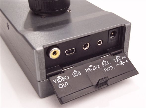
Notices
Documentation Copyright 2011 Tetracam Inc. All rights reserved.
Camera software Copyright 2000-2011 Tetracam Inc.
Printed in the United States of America.
Specifications subject to change.

This software and documentation are copyrighted materials. The making of
unauthorized copies is prohibited by law. No part of the software or
documentation may be reproduced, transmitted, transcribed, stored in a
retrieval system or translated into any human or computer language without
the prior written permission of Tetracam, Inc.

Unless otherwise provided by written agreement with Tetracam Inc., this
publication is provided “as is” without warranty of any kind, expressed or
implied, including, but not limited to, the implied warranties of merchantability
or fitness for a particular purpose. Some states do not allow disclaimer of
expressed or implied warranties in certain transactions, so this statement
may not apply to you.

While reasonable efforts have been made to assure the accuracy of this
document, in no event will Tetracam be liable for direct, indirect, special,
incidental, or consequential damages resulting from any defect in this
publication or the associated software. Tetracam Inc. reserves the right to
change this document at any time without obligation to notify anyone.

Trademarks
Windows™ is a registered trademark of Microsoft Corporation.
Photoshop™ is a registered trademark of Adobe Systems.
InstallShield™ is a registered trademark of InstallShield Software Corp.
IBM™ is a registered trademark of IBM Corporation
Other brand or product names are trademarks of their respective holders.

                    Version 2.3 - Last Modified May, 2011

                     Tetracam Inc
                     21601 Devonshire Street
                     Suite 310
                     Chatsworth,CA 91311 USA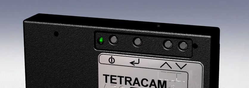
Page 2 Agricultural Camera User's Guide

Table of Contents
NOTICES ....................................................................................................... 1
TRADEMARKS ................................................................................................ 1
ABOUT THIS GUIDE ........................................................................................ 4
QUICK START INSTRUCTIONS .......................................................................... 5
UNPACKING THE BOX..................................................................................... 6
GETTING STARTED ........................................................................................ 7
   System Requirements ............................................................................ 7
   Software Installation ............................................................................... 7
   Hardware Installation .............................................................................. 8
   Camera Interconnections........................................................................ 9
   ADC Optics and Filters ........................................................................... 9
   Spectral Response ............................................................................... 10
   The Calibration Image .......................................................................... 11
   Compact Flash Cards ........................................................................... 11
CAMERA OPERATIONS.................................................................................. 12
   Power Up .............................................................................................. 12
   Button Functions ................................................................................... 12
   Initializing Internal Memory ................................................................... 13
   Toggling USB Mode.............................................................................. 13
   Taking Pictures ..................................................................................... 13
   Controlling the Viewfinder ..................................................................... 14
THE CAMERA VIEWFINDER............................................................................ 14
THE CAMERA MENU SYSTEM ........................................................................ 16
ALARM MODE .............................................................................................. 19
CONTINUOUS CAPTURE MODE ...................................................................... 20
CHOOSING AN IMAGE FORMAT ...................................................................... 21
GPS OPTION INSTALLATION AND USE............................................................ 22
EVENT LOG FILE .......................................................................................... 23
HOST SOFTWARE ........................................................................................ 25
   PixelWrench2 ....................................................................................... 25
   SensorLink ............................................................................................ 25
   Connecting the Camera for Driver Installation ...................................... 26
   USB Disk Configuration: ....................................................................... 26
   Managing and Processing ADC Images in PixelWrench2 .................... 27
   Configuring the Camera with Pixelwrench2 .......................................... 28
THE 16-PIN MULTI I/O CONNECTOR .............................................................. 29
MOUNTING THE UNIT ................................................................................... 29
CAPTURE DELAYS FOR AERIAL PHOTOGRAPHY ............................................... 30
PROGRAMMERS REFERENCE – FILE FORMATS ............................................... 31
PROGRAMMER’S REFERENCE – C AND VISUAL BASIC SUPPORT ....................... 32
TETRACAM RS232 SERIAL CONTROL COMMANDS .......................................... 36
SPECIFICATIONS .......................................................................................... 37
FCC EMISSIONS STANDARDS INFORMATION ................................................... 38
SUPPORT INFO ............................................................................................ 38
INDEX ......................................................................................................... 39

      Agricultural Camera User's Guide                                                                  Page 3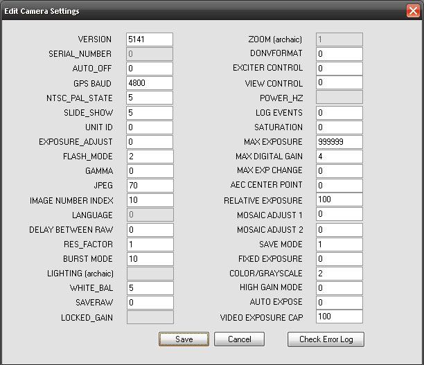
About This Guide

 The Agricultural Digital Camera User’s Guide contains general information
 about the ADC product, covering installation, operation, options and
 accessories, warranties, and technical support. The information is specific to
 firmware version 5.141 and later – users with earlier firmware should upgrade
 so that their units conform to the information herein.

 The ADC is a single sensor digital camera designed and optimized for
 capture of visible light wavelengths longer than 520 nm and near-infrared
 wavelengths up to 920 nm. The primary designed use of this product is for
 the recording of vegetation canopy reflectance. The resulting images are
 suitable for derivation of several vegetation indices.

 The purpose of this document is:
 1.   To guide the user through the installation of the product and its
      supporting software on its target host computer system.
 2.   To describe the basic camera operating procedures.
 3.   To describe the interaction between the camera’s interface software and
      the image editing and archiving software it may be used with.

 This document assumes that the user is familiar with the operation of an IBM-
 compatible personal computer running the Windows XP, Windows Vista, or
 Windows 7 operating system. The user should be familiar with the use of
 near infrared images to evaluate the condition of plant life.

 An electronic (.PDF) version of this manual is supplied on the installation CD
 and is available at www.tetracam.com.

Page 4                              Agricultural Camera User's Guide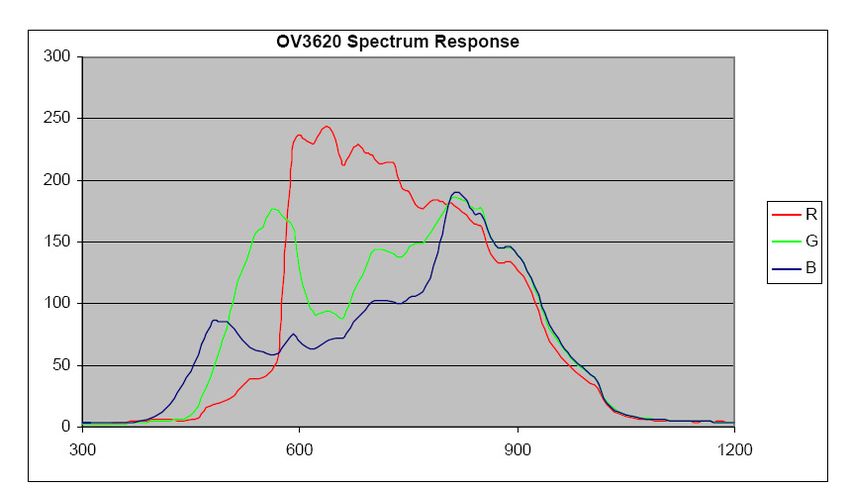
Quick Start Instructions

Install the 8 AA alkaline batteries and activate the unit by pressing the
ON/OFF button on the top edge of the housing (leftmost of the 4 small
buttons). After approximately five seconds, the LCD display should activate.
Take pictures by pushing the largest button on top of the camera housing.
STREAMING DRIVERS MUST BE INSTALLED BEFORE CONNECTING
THE CAMERA TO A USB PORT! Insert the CD and answer the installation
questions. Have your Windows installation CD available in case your system
does not have USB stream support installed. You will be asked for the
Windows setup CD if this is the case. If you operate the camera as a USB
Disk, no driver software needs to be installed.
Install PixelWrench2 before connecting the camera to the computer. This
program is needed to manage connections to the camera and extract useful
data from the NIR images the camera captures.
To review your pictures in the camera, press the MENU/SELECT button to
the right of the ON/OFF button. A menu should appear. Select items in the
menu using the two UP and DOWN buttons to the right of the menu button.
These buttons allow you to scroll through the selections. Pressing the
MENU/SELECT button activates a selection. The "Review" selection gives
you access to images in the camera for display on the LCD.
To view your pictures on a computer, you may remove the CF card and install
it in a CF card reader, or plug the camera into the USB interface on your
computer.
From PixelWrench2, you may open previews of the images on the CF card or
in the camera and extract them for viewing and analysis. Consult the online
manual for PixelWrench2 and the camera for more detailed instructions.
If the camera is operated as a USB Disk, you can find the pictures with the
File Explorer, and Open or Move them with Windows Mouse operations.
When you are done with the camera, turn it off by pressing the ON/OFF
button.

      Agricultural Camera User's Guide                                 Page 5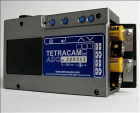
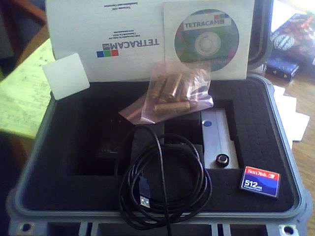
Unpacking The Box

    This is what you should find in the box.
         •    A Hardened Plastic Camera Case
         •    An ADC Agricultural Digital Still Camera
         •    A C-Mount Objective Lens
         •    A CDROM with Installation Software and Documentation
         •    Product and Accessory Documentation
         •    A USB Interconnection Cable
         •    A Set of Eight AA Batteries
         •    A Compact Flash Memory Card
         •    An AC Power Adapter
         •    A White Teflon Calibration Plate
    Your camera comes with a one-year warranty against defects. The warrantee
    is a .pdf file on the supplied CDROM. You should print, fill out, and send in
    the warranty card to register the camera and qualify for additional software
    and firmware updates.
                                                  Documentation

Teflon Calibration
Plate

                                                               Installation
                                                               Software CD

Kit of 8 AA
batteries                                                        ADC Digital Still
                                                                 Camera
C-Mount Lens

AC Power Adapter
                 Figure 1 - Contents of the Shipping Box
                      USB Cable                             CF Memory Card

  Page 6                               Agricultural Camera User's Guide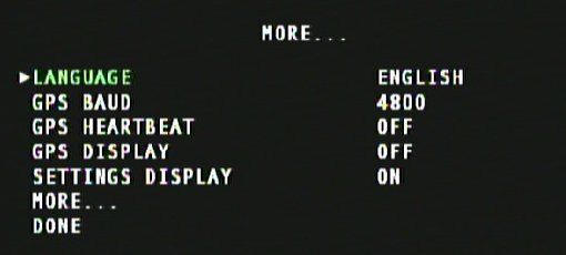
Getting Started

System Requirements
Any IBM-compatible personal computer with a free USB serial port can be
used to operate and configure the Camera. The unit produces RGB color
images that are each approximately 9 million bytes in size when the images
are rendered on a computer screen. You should select a computer with
resources that can support manipulation of images that are this large. Our
recommendations for a minimum configuration are:
    •    1 GHz or better processor, Intel or AMD
    •    Windows 7, Vista or XP operating system
    •    512 megabytes of SDRAM
    •    24 bit color graphics adapter at 1024 x 768 or better resolution
    •    1024 x 768 or higher display
    •    Large hard disk drive with 10 GB or more free space

The camera can be made to operate on less capable systems, with penalties
in speed and convenience.

Software Installation
The software installation CD contains the svstream hardware drivers to allow
Windows to recognize the camera, PixelWrench2 (PW2) installer, and
Microsoft .NET Framework 3.5 pre-requisite for PW2. The CD also contains
a readme.txt file that documents the software installation procedures.
Install the Microsoft .NET Framework 3.5 by executing the file on the CD
named dotnetfx35.exe. Once complete, navigate to the PW2 folder and run
the PixelWrench2 installation by executing the setup.exe file. You may be
prompted to restart your computer after the installation is complete.
The first time the camera is connected to the computer’s USB port, Windows
will install a set of drivers in order to communicate with the camera. The
drivers can be selected manually by directing windows to the svstream.inf file
on the CD. The CD also contains an image file called Driver_Installation.png
that shows the driver installation steps.

        Agricultural Camera User's Guide                                    Page 7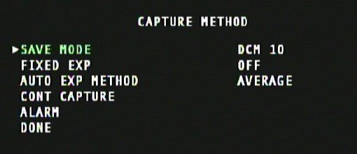
Hardware Installation
The ADC runs on 8 AA batteries or 12VDC external power connected to the
power connector on the camera's right side. To install batteries, open the
battery door on the side of the camera. Insert fresh AA batteries, ensure the
direction and polarity agree with the symbols on the product label. The
camera will operate on Alkaline, NiCad or NiMH
batteries. Close the battery door to complete the
battery installation.
The camera will operate on external power with or
without batteries installed. Connect a 12 VDC (+/-
2.5 volts, center positive) supply to the connector
provided. The camera is intended to be compatible
with 12V vehicle power, A vehicle accessory
adapter can be used to power the unit if desired.
The ADC cameras come in three housing options.
The standard ADC is packaged in an aluminum
case, has buttons for user input, and has a built in
LCD display to show pictures and menus to an
operator. The ADC Air has a weatherproof case
without buttons and relies on a connected PAL or NTSC video monitor or TV
to view pictures and menus. The ADC Lite has a lightweight plastic case,
making it suitable for use in small UAVs and also relies on PAL or NTSC TV
displays for menu operation and managing pictures. The ADC Air and ADC
Lite do not turn on and off with a power button, but are only turned on or off
by turning on or off the external power supplied to the camera.
All the models share the same electronics. Illustrations that follow use views
from all three versions.
ADC ADC Air ADC Lite
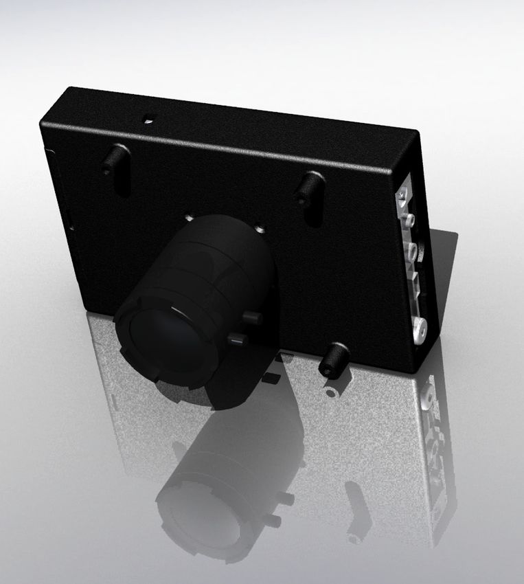
Page 8 Agricultural Camera User's GuideCamera Interconnections
Video Out – configurable by menu for NTSC or PAL
USB – The main USB I/O connector.
RS-232 (GPS IN) – A mini-stereo (3 pin) connector allocated for connection
of a GPS unit. A 3.5mm stereo phone plug tip, ring and sleeve is camera
receive, camera transmit, and ground, respectively. The camera serial port is
configured 4800 – 8 – N –1, the NMEA 0183 standard configuration. The
camera firmware is
designed to listen for the
NMEA RMC sentence. If
the sentence is found, it
is written to the image
status string (header) for
extraction by application
software. The serial port
can also be used to
control the camera from
an external serial
interface, using simple
text commands
described in the
Programmers Reference
section.
Trigger – Plug the optional external trigger unit into this connector.
Power – The camera requires a 12VDC, center positive polarity supply
capable of delivering 0.5 Amps continuous. The supplied wall plug type
supply connects to this jack.
Multi I/O – This 16 pin connector is allocated for use with certain Tetracam
accessories. Call us to discuss your requirements if you need features such
as a remote display, control buttons for triggering, menu operations, power
switching, or other remote control functions.
ADC Optics and Filters
The camera is typically supplied with one of two lenses:
8.5mm C-mount fixed focal length lens (standard)
4.5 to 12mm CS mount vari-focal lens (optional)
Agricultural Camera User's Guide Page 9The vari-focus lens is adjustable from 4.5 mm (wide angle) to 12mm (slight
telephoto) focal lengths. After making a focal length adjustment, the focus
must be checked and adjusted. The lens aperture is also adjustable.
The standard camera is supplied with an 8.5mm fixed focal length C-mount
lens with a C to CS mount adapter ring. An infinity focus mark is placed on
the fixed focal length lenses for reference. Set the lens to this mark when
shooting at distance -- aerial images, for example. ADC cameras are
designed for use with either CS-mount or C-mount type lenses. C-mount
lenses require a C to CS mount adapter ring (5 mm extension) to function
properly. Any lens fitted to an ADC camera should be designed for use with
½” or larger optical format sensors.
Permanently mounted behind the lens is a yellow long-pass filter. Touching
this filter should be avoided. Clean using a soft clean cloth or lens tissue.
Spectral Response
The CMOS sensor in the camera is screened with a Bayer RGB filter array in
a “checkerboard” pattern. The graph below shows the response of the sensor
to different bands of light through the red, green and blue filters. A blue
absorbing glass filter is used to eliminate the blue sensitivity, and the blue
pixels in the sensor are used to measure NIR (Blue Curve). The image is
then processed in Pixelwrench2 to subtract the measured NIR from the blue
and red bands to produce the final Red/Green/NIR image.
ADC Bayer Filter Response Curve
Blue
Blocking
Filter
(Yellow Visible Red Near
Glass) and Green Infrared
Light Light
Page 10 Agricultural Camera User's GuideThe Calibration Image
An important part of the entire camera and software system is the need to
calibrate the software supplied with the camera. Calibration consists of taking
an image of the Teflon calibration tag under the same lighting conditions as
the images under study. This image is used to teach the application software
what the spectral balance of that day's sunlight is. The ratio of red/NIR or
green/NIR is then applied as an offset to the calculation of the various
vegetation indices.
If a calibration image is not taken within an hour or two of pictures in the field,
the vegetation index calculations will be less accurate, and the pictures may
not be as useful.
Place the calibration target on the
ground or hold it level to the ground
and photograph it. It should nearly fill
the entire frame and it must not be
overexposed. Make sure to avoid a
direct reflection of the sun. The
sample image on the right is of a
properly exposed calibration target.
Later, when the pictures are
imported to the host computer, the
calibration picture on the CF card
will be used to refine the vegetation
index calculations using the supplied
software applications. Calibration Target Image
Compact Flash Cards
The unit can handle Compact Flash (CF) cards up to 2 GB. Since stored
images are about 3 MB each, a 512 MB card is the minimum recommended.
A CF card is supplied with the unit.
Note: The ADC cannot take pictures without a compact flash card installed.
We recommend that the unit's power be turned off when the compact flash
card is replaced. CF cards manufactured by SanDisk have proven most
reliable in our testing of the unit.
The camera is usually operated away from the host computer. If a compact
flash memory reader is present on the host computer, the software can
extract images directly from the card, without having to connect the camera.
This allows the camera to be left in the field, or attached to a vehicle. The CF
card is exchanged to bring the pictures to a host computer.
Agricultural Camera User's Guide Page 11Large CF Card Issues
When CF cards with capacities in excess of 2 Gigabytes are used they must
be formatted as FAT32 cards on the PC. The camera is not capable of
initializing CF cards to FAT32 format. Format the card using 32kb cluster
(allocation unit) size for faster camera boot times. Care must be taken to label
the volume TTCDISK0 during formatting on the PC. The volume information
is used by PixelWrench2 to identify the device as a Tetracam camera when it
appears as a USB Disk.
Camera Operations
Power Up
The camera’s Power ON/OFF button is the leftmost button along the top edge
of the camera. It is marked with the circle and bar symbol as shown in the
next illustration. Press and release the button to power the camera on or off.
A few seconds after power up, the LCD will illuminate and begin displaying
the live viewfinder image. Connect an optional video monitor to an ADC Air or
ADC Lite to see the viewfinder.
Take Pic / Exit
Up / Down
Power On/Off Menu / Select
Button Functions
The Menu / Select button will invoke the camera’s menu as well as select
menu options. The Up / Down buttons are used to scroll through menu
options and file lists. When in a menu prompt, press the Take Pic / Exit button
to immediately exit the menu and go back to the viewfinder screen, ready to
take pictures. From the viewfinder screen, press Up or Down to adjust the
exposure time and press Take Pic to capture an image.
Page 12 Agricultural Camera User's GuideInitializing Internal Memory
In the event that the camera’s internal memory develops faults, it must be
reinitialized for the unit to power up correctly. Holding the shutter button and
down arrow button while the power button is pushed will force the camera to
initialize its internal memory.
Toggling USB Mode
When the camera is connected to a Windows computer via the USB port, it
will be seen by Windows as either a USB Mass Storage Device ( USBMODE
= DISK ) or a SoundVision Camera ( USB MODE = CAMERA ). The USB
MODE setting can be changed in the camera’s menu system, however there
is also a way to switch modes during power up. While powering the camera
on, press and hold the Menu / Select button until the camera is fully booted to
toggle the USB mode. USB mode can also be set using the host software.
NOTE: When the camera is connected to Windows as a USB DISK, it should
not capture pictures – it should function as an attached disk drive.
Taking Pictures
Taking a picture requires only aiming, adjusting focus if needed, and pressing
the trigger button. As you view the live image on the display you will notice a
general change in brightness, this is the camera auto adjusting the exposure
time. Allow a second or two for this process to complete before triggering.
Depending on the lens
fitted to the camera, you
may have adjustable
focus, zoom and aperture. Focus
In general for daylight Adjustment
photography of vegetation, Ring
it is preferable to close the
lens opening somewhat,
Aperture
called "stopping down".
Adjustment
This generally increases
Ring
image sharpness and
contrast. It also increases
depth of field.
Agricultural Camera User's Guide Page 13Controlling the Viewfinder In daylight conditions, a properly set aperture will produce a fairly dim viewfinder image on the display so that NIR data is not over-exposed. For certain pictures it may be useful to adjust the exposure using the UP and DOWN arrow keys while the viewfinder is running. UP makes the target image brighter, DOWN makes it darker. When in auto-expose mode, pressing the UP or DOWN buttons will increase or decrease the exposure by 1/6 f-stop for each press. When in fixed expose mode, pressing the UP or DOWN buttons will increase or decrease the exposure time by ½ millisecond for each press. Once the viewfinder image is satisfactory, capture can be initiated with the Take Pic button or via the external trigger box. The Status LED will turn from green to red, indicating that the camera is busy capturing and saving the image. After a capture, the camera completes the compression and storage of the image and the status LED returns to green indicating the camera is ready. At this time the image will be displayed momentarily (controlled by QUICKVIEW). If the image format is set to RAW, the cycle is completed much more quickly. The Camera Viewfinder Once the camera is powered on, after a few moments it finishes its initial bootup sequence and enters the viewfinder, where it is ready for image captures. A live video image of what the camera “sees” will be shown on the screen. This is the normal ready-state of the camera. From this state, the user may adjust the exposure time up or down, using the UP or DOWN buttons, enter the menu system using the MENU / SELECT button, or capture images using the TAKE PIC button. An overlay of information is shown on the viewfinder by default and can be turned off in the camera’s menu. Below are shown the different points of information, arranged as shown on the viewfinder screen, with descriptions for each. Page 14 Agricultural Camera User's Guide
USB Mode – USB DISK MODE will be displayed if the camera is set to
enumerate as a USB DISK when connected to a Windows computer via USB.
Save Mode – Displays DCM, R8, or R10 for the type of image the camera is
set to save. DCM is a compressed 10-bit format, while R8 and R10 are 8-bit
and 10-bit RAW file formats, respectively.
Cont. Capture – This parameter is displayed in green when Continuous
Capture is enabled, and in red when capturing, and shows the amount of
Continuous Capture delay set.
Alarm – This parameter is displayed in green when the Alarm is set to power
up the camera at some time, and will show in red when the camera has been
powered on by the Alarm.
Exposure Mode – If a FIXED EXPOSURE is set, this parameter will display
the word “FIXED” in red along with the set exposure time, in milliseconds.
With Fixed Exposure turned OFF, this parameter will display “AUTO A” or
“AUTO P”. The “A” or “P” designation indicates the METHOD of Auto
Exposure, Average or Peak. A positive or negative number may follow this
parameter, indicating the Exposure Adjust setting, controlled by the UP or
DOWN buttons from the viewfinder.
Date / Time – Date and Time is displayed.
Picture Count – This parameter shows the number of images stored on the
CF card.
*note: SETTINGS DISPLAY in the menu controls the displaying of the above
listed parameters. GPS DISPLAY and GPS HEARTBEAT in the menu
controls the displaying of the parameters listed below.
GPS Position – With a GPS receiver connected and communicating with the
camera, position coordinates will be displayed. If the GPS receiver loses its
signal lock, “WAITING FOR GPS” will be displayed in RED until it recovers its
signal lock.
GPS Heartbeat – This is an indicator to confirm that a connected GPS
receiver is sending data to the camera. Every time the camera gets a new
packet of data, the “/” character in “GPS/” will toggle back and forth, between
the “\” and “/” characters, and the status LED will briefly flash from green to
red.

       Agricultural Camera User's Guide                                 Page 15
The Camera Menu System The camera can be configured from the host computer via the USB connection or by use of the menu selections accessible with the controller and video display. Operation of the menu system uses the three rightmost buttons on the controller: the SELECT, UP and DOWN buttons. To enter the menu system, the SELECT button is pressed once. Sub menus appear, or menu items which have values to the right of them. To select a submenu, use the UP/DOWN buttons to move the cursor up or down to the desired submenu entry. Press the SELECT key to display the next menu page in the tree. If a submenu is not available, (REVIEW cannot be accessed unless pictures have been taken) it will be gray in the display instead of white. The selected entry is hi-lighted in green. To change a menu item value, navigate to it by pressing the UP/DOWN buttons, and select it by pressing SELECT. The menu item’s value will turn green, indicating that it is selected. Use the UP/DOWN buttons to scroll through the available values, and SELECT again to set the value. Select the DONE menu item on any menu page to save any settings on that page and exit back to the previous screen. To exit the menu without saving any settings, avoid selecting “DONE” and exit using the TAKE PIC button. NOTE: The menu system can be exited at any time (without saving) by pressing the TAKE PIC button. MAIN MENU REVIEW – options for viewing or deleting stored images. INFO – view battery status, firmware version and storage card space used / free. CAPTURE METHOD – set file save mode, toggle fixed or auto exposure, toggle single or continuous capture settings, set alarm capture mode. SETUP – set video and USB mode, menu language, date / time, quickview, GPS and viewfinder, restore defaults, format memory card. DONE – Every menu page ends in a DONE selection. Selecting DONE will save any settings that exist on that page and return to the previous screen. Page 16 Agricultural Camera User's Guide
REVIEW
THUMBNAIL – displays
four images at once on
the screen to quickly scroll
through images while
viewing them.
FULL SCREEN – show
full size images one at a
time
DIRECTORY – show a list of saved images
DELETE ALL – erase all images on memory card at once
All images are listed in order from most recent to oldest. Images can be
deleted one at a time if selected individually.

INFO
Shows the power supply
voltage, camera firmware
version number, used,
free, and total space on
the memory card.

CAPTURE METHOD
SAVE MODE – set the type of image file the camera saves. See “Choosing
An Image Format” section for more help.
FIXED EXP – select an
exposure time in
milliseconds or OFF for
auto-exposure mode.
AUTO EXP METHOD –
select PEAK if the subject
is the brightest part of the
image, or AVERAGE for
all others cases.
CONT CAPTURE – select to configure Continuous Capture mode.
ALARM – select to configure Alarm mode (not available on ADC Air or ADC
Lite).

       Agricultural Camera User's Guide                               Page 17
SETUP VIDEO – sets the camera to output NTSC or PAL standard video feeds. USB MODE – sets the USB MODE to CAMERA or DISK. The camera will reboot if this setting is changed. LOG EVENTS – turn this ON to capture events to a log file. DATE / TIME – Select this to set the time and date for image stamps. QUICKVIEW – sets the color process of the preview of a newly captured image and the amount of time the preview is displayed on the viewfinder screen. MORE… – More setup options. MORE… LANGUAGE – Set the menu language. GPS BAUD – Set the serial connection data rate between the camera and a GPS receiver. GPS HEARTBEAT – When ON, an indicator is shown on the viewfinder screen and the status LED briefly flashes from green to red, signaling each time the camera receives information from the GPS receiver. GPS DISPLAY – When ON, GPS coordinates are displayed on the viewfinder screen. SETTINGS DISPLAY – Toggles the display of settings information on the viewfinder screen. FORMAT CF CARD – select this option to re- format the CF card. RESTORE DEFAULTS – select this option to return all settings to factory defaults. This is recommended any time the camera’s firmware is upgraded. Page 18 Agricultural Camera User's Guide
Alarm Mode
Note: ADC Air or ADC Lite cameras are designed to always be powered on
while connected to a power supply. For this reason, Alarm Mode is not
available on these models.
The Alarm mode of operation causes the camera to power up on its own, at a
preset time, and take a picture, or series of pictures at set intervals. Below is
shown the ALARM settings screen of the camera’s menu system with
explanations of the parameters to set and examples.
With DAY, HOUR, MINUTE and INTERVAL all set to OFF, the alarm is not
armed – this is the default settings for Alarm mode.
PIC. COUNT – this is the
number of images (16
max) the camera will
capture every INTERVAL
number of minutes,
starting at the time set via
the DAY, HOUR, MINUTE
settings.
INTERVAL – with
INTERVAL set to OFF, the camera will capture only one image at the
designated alarm time. With interval set to a number (in minutes), the camera
will wake up every INTERVAL number of minutes, after the initial alarmed
capture, and take another picture, until PIC. COUNT number of pictures have
been captured. Once the camera has captured all INTERVAL images
specified by PIC. COUNT the camera is finished its job for that Alarm session
and will not wake up for another capture until the next Alarm time set with the
DAY, HOUR, and MINUTE setting.
DAY, HOUR, MINUTE – These parameters are quite intuitive when all set.
For example, to have the alarm wake up the camera to capture an image on
every Monday at 1:35pm, set DAY to MON, HOUR to 13 (24 hour military
time) and MINUTE to 35. However, any or all of these three parameters can
be OFF yet the alarm is still set.
Examples:
Leave DAY and HOUR OFF and set just the MINUTE to 35 – the camera
wakes up every hour when the clock reaches 35 minutes.
Leave HOUR OFF and set the DAY to Monday and MINUTE to 35 – the
camera will wake up every hour on the 35 minute mark, as in the previous
example, but only on Mondays.
Leave DAY OFF but set HOUR to 13 and MINUTE to 35 – the camera will
wake up every day at 1:35pm

       Agricultural Camera User's Guide                                  Page 19
Leave DAY, HOUR, and MINUTE OFF and set INTERVAL and PIC. COUNT both to 1 – even though PIC. COUNT is set to only capture one image per job, with DAY, HOUR, and MINUTE OFF, a new job starts every INTERVAL minutes, so the camera would continuously wake up every minute and capture an image, forever! Leave DAY and MINUTE OFF, set HOUR to 10, INTERVAL to 30 and PIC. COUNT to 16 – the camera will wake up every day at 10am to capture an image and then wake up again every 30 minutes until 16 images have been captured. So the camera wakes up at 10am, 10:30am, 11am, 11:30am,... 5pm, and lastly at 5:30pm. The next morning at 10am, the cycle starts again. Continuous Capture Mode This mode of operation causes the camera to begin taking pictures when the TAKE PIC button is pressed, and to continue taking pictures until the button is pressed again. It is the simplest way to operate the camera on a remote aerial vehicle. The rate of capture is controlled by the file format selected, and the additional delay set between pictures. CONT CAPTURE – turns Continuous Capture mode ON or OFF CONT DELAY – sets the minimum amount of delay between captures. RAW images take less than a second to save while DCM images may take about five seconds (compression), so very short delay settings (such as 5 seconds or less) may not be realized because of file save times. Range is from 0 – 60 seconds. NOTE: For fastest possible operation , configure the camera for RAW8 image SAVE MODE and LOG EVENTS OFF. Page 20 Agricultural Camera User's Guide
Choosing An Image Format
The highest rate of capture is with the 8 Bit RAW file format, at about one
picture per second. The speed depends in part on the features of the CF
card. For users who require more precision, the 10 bit RAW format is the next
fastest.
The RAW files are quite large – 6 megabytes for the 10 bit format and 3
megabytes for the 8 bit format. Compression (DCM format) cuts the size of
the files in half, but takes longer to capture. We therefore think of DCM
compressed continuous mode as “low speed”. Besides the smaller file size,
another advantage of the DCM format is that the files contain previews which
speed up the image access speed using Pixelwrench2.

File       -----Advantages-----------     ----------Disadvantages---------
Format
RAW 8      Fastest cycle time             Less dynamic range, no embedded
bit                                       previews
RAW 10     Fastest cycle time with        Big files, no embedded previews
bit        full dynamic range
DCM 10     Smallest file size with full   Longest time between pictures (up
           dynamic range                  to 5 seconds)

The table above shows the relative advantages and disadvantages of camera
file formats. These apply to all modes of operation.

      Agricultural Camera User's Guide                                  Page 21
GPS Option Installation and Use Your ADC will capture and append the most recent GPS data string to each image as it is taken. The following requirements apply; Your GPS receiver must be configured to output the standard NMEA "GGA" sentence. The default output protocol for NMEA sentences is 4800 baud, 8 data bits, 1 stop bit, no parity. Your receiver should allow you to configure it for GGA at 4800:8:1:N. If your GPS receiver can be configured for a higher baud setting you should take advantage of the feature, since it will make the GPS data more accurate as less time is lost transferring the messages. The menu in the camera has an entry for the GPS baud. There is also an advanced setup screen, accessible via Pixelwrench2 that can save a higher baud rate. The GGA sentence is emitted once per second and contains the following fields: 1. Time UTC 2. Latitude and Longitude 3. Fix quality 4. Number of satellites tracked 5. Horizontal dilution of position 6. Altitude in meters MS 7. Height above MSL Attach the optional serial cable to the small serial connector (see the illustration in the Hardware Installation section of this manual). Attach the other end to the serial port of the receiver. The most recent GGA sentence sent to the camera will be appended to the image data file. You can print (or hide) the GGA sentence on the image using Pixelwrench2. On the Pixelwrench2 Camera menu select Enable GPS Tagging to have the GPS data placed along the upper edge of the image. The camera firmware also supports an event or position logging system that will exactly place the GPS locations versus the time pictures are taken with a resolution of 10 milliseconds. Page 22 Agricultural Camera User's Guide
Event Log File
When LOG EVENTS is set to ON in the SETUP menu, the camera will
maintain a file with a record of key events and time stamps that can be used
to accurately position the location at which the picture was taken.
Generally, a GPS receiver is connected to the camera serial port that sends
$GGA… and $RMC…position strings to the camera. The Log Events feature
is used most often with aerial photography, when the GPS points of interest
will be directly below the camera, so that the camera will capture images of
subjects at those coordinates.
When the option is enabled, the camera creates the file CURRENT.LOG on
the CF memory card in root folder. If there is a pre-existing CURRENT.LOG
file, the file is moved to the image folder (TTCADC in the case of the standard
ADC) and renamed according to the image numbers that were captured while
the camera was last in operation.

Example:

If images 31, 32, 33, and 34 were captured, there will be event log records for
each of those captures in the file. The file is scanned for image capture
records, and the smallest and largest image numbers found are used to
compose a log file name. In this case, the file would be renamed to
00310034.LOG. The first four characters of the new file name are the lowest
image capture record in the file, the second four letters are the highest image
capture record in the file.
A typical Event Log file is shown on the next page. Each line shown is one
record in the file, terminated by a newline character and NULL. In the
illustration, the NULL characters are hidden and additional line feeds are
added for clarity.
Log files can accumulate on the camera’s CF memory card. If they are not
erased from time to time, the resources to capture large numbers of images
may not be available. The files can be deleted from the CF card using the
conventions of the desktop PC.
Log files are much easier to manage if the camera is set up to operate in the
USB Disk mode described earlier. The Log files are not directly accessible
from Pixelwrench2 using the stream interface. When the camera shows up as
a folder window on the desktop, as it does in USB Disk mode, the moving
and deleting of files is trivial.

       Agricultural Camera User's Guide                                Page 23
The CLK record is added when
the camera powers up. It shows
Every Record has a “Ticks” Field
the camera date and time.
that shows the cameras internal
clock count of 10 millisecond ticks.
The count 104 means that the CLK
record was written 1.040 seconds
after power on.
CLK 000000104 Date/Time: 10/22/2009 15:15:01
GPS 000002006 00217 $GPRMC,192254.00,A,2942.79012,N,08223.30667,W,000.0,000.0,221009,03.3,W,A*0B
GPS 000002064 00217 $GPRMC,192254.00,A,2942.79012,N,08223.30667,W,000.0,000.0,221009,03.3,W,A*0B
$GPGGA,192255.00,2942.79047,N,08223.30663,W,1,04,2.58,00040,M,-031,M,,*5D
IMG 000003049 00218 If a GPS is connected, an entry
is made each time a GPS
GPS 000003102 00218 $GPRMC,192302.00,A,2942.79461,N,08223.30899,W,000.0,000.0,221009,033,W,A*06
update string is received.
EXT 000003217 External Event Bit Different GPS messages are
concatenated as they come in
GPS 000003280 00219 $GPRMC,192302.00,A,2942.79461,N,08223.30899,W,000.0,000.0,221009,033,W,A*06
$GPGGA,192303.00,2942.79517,N,08223.30922,W,1,04,2.58,00062,M,-031,M,,*55
The ADC AIR system does not have a power When a picture is taken, a record is written showing the
button. In these systems, a 3.3V external event system ticks at the end of integration. The camera can only
signal can be connected to the external signal do one thing at a time, so there will always be a system
contact for the remote PWR SW. When the line ticks offset between capturing a picture and the GPS
pulses, an EXT record will be written to the log file. messages. The actual position of the camera when the
Since the time in a GPS record is offset by the picture is captured can be approximated by interpolating
transmission time, an accurate external tick pulse between the two GPS messages using the system ticks.
from the GPS can be recorded here to improve
accuracy.
Page 24 Agricultural Camera User's GuideHost Software
The software supplied on the installation CD is made of several major
components:
1. An image acquisition and manipulation application, named Pixelwrench2
2. An optional GPS guided camera trigger application named SensorLink
3. A camera interface DLL for extracting images from the camera or CF
card, and converting them to Windows bitmap format for display.
The goal of this software is to allow the user to extract the NIR / Green / Red
images from the camera, and convert the proprietary format into a Windows
bitmap according to rules specified by the user. (The NIR band can be
mapped to Green, Red or Blue in the final image, as can the two visible
colors). The host softwares have built in help systems for further instructions
not covered in the this manual.
PixelWrench2
PixelWrench2 (PW2) is a powerful image editing program with several tools
specific to multi-spectral images and working with Tetracam ADC and MCA
cameras. Open the PW2 folder and run setup.exe. This will install
PixelWrench2. See the PixelWrench2 online help for more information.
PW2 can open ADC proprietary DCM10, RAW10 and RAW8 image files
along with several standard image file types (BMP, JPEG, TIF, PNG etc.).
SensorLink
If you purchased the optional SensorLink application you will find a folder by
that name on the CDROM included with the camera.
SensorLink is a GPS waypoint triggering application enabling camera
triggering at pre-defined waypoints. It uses the same .NET 3.5 framework.
Simply run setup.exe in the SensorLink folder to install it. See the SensorLink
online help for more information.
Agricultural Camera User's Guide Page 25Connecting the Camera for Driver Installation (Windows XP only) Power up the camera and make sure it not in USB DISK mode. If it is, you can toggle this mode from the menu or by power cycling the camera with the MENU / SELECT held down. Once powered up in USB CAMERA mode (not USB DISK mode), connect the USB cable to a USB port on the computer and to the connector labeled USB on the camera interconnect panel. The first time the camera is connected to a USB port, Windows will launch the New Hardware Found wizard. This will guide you through installation of the camera driver called svstream.sys. If you plan to operate the camera as a USB DISK, skip to the next section. Do not let Windows search for the driver. In every case select the option where you specify the name and location of the driver. The driver svstream.sys and its information file svstream.inf will be copied to your Windows/system32/drivers folder when you install either PixelWrench2 or SensorLink. When the driver installation wizard asks for a location browse to Windows/system32/drivers. In both PixelWrench2 and SensorLink, you are required to specify the camera type prior to accessing the camera. In PixelWrench2, on the Camera Toolbar, click the small down arrow on the top button (Status). Select ADC as your camera type. This loads the correct DLL for use with the ADC. See the PixelWrench2 online help file for further specifics on camera communications. USB Disk Configuration: With the introduction of firmware version 5.097 the MCA can be configured to appear as a USB disk drive to the operating system. For Windows Vista, or operating systems other than Microsoft, the camera must be operated as a USB Disk device. To toggle the USB mode between DISK and CAMERA, change the USB MODE setting in the camera’s menu SETUP page and then select DONE – the camera will reboot automatically with the new mode set. You can also toggle the USB MODE setting by simply holding down the MENU / SELECT button during the entire power-up sequence. However the camera is configured, it will be recognized when the Pixelwrench2 application is started. In the original stream mode of operation, Pixelwrench2 is the only way to exchange data with the camera over a USB link. When the unit is configured as a USB DISK, files can be dragged and dropped to and from the camera from any personal computer that has USB disk drivers. Page 26 Agricultural Camera User's Guide
Managing and Processing ADC Images in PixelWrench2
The ADC system writes losslessly compressed image files or RAW files to the
CF card. These images carry the extension *.DCM or *.RAW. PixelWrench2
offers all the tools needed for management of ADC images. Please refer to
the help system in the menu of PixelWrench2 for detailed information.
There are five ways to retrieve images:
1. Remove the CF card from the camera and copy its contents to a folder on
your computer.
2. With the camera connected as a USB DISK, transfer images to the host
computer using the Image Transfer and GPS Distiller Tool, accessed by
PixelWrench2’s Edit menu.
3. Power up the camera in USB DISK mode and copy *.DCM or *.RAW files
directly to the computer, then open with (drag and drop into) PixelWrench2.
4. In PixelWrench2, open the camera toolbar and click Open Camera. The
camera inventory screen will appear with thumbnails of all the images. Select
an image (or images) then click Load. The image(s) will be extracted from the
camera, color processed using the matrix values entered and stored by the
DLL and displayed on screen as an RGB bitmap.
5. In PixelWrench2, click Save DCA on the CameraToolbar. A file save
dialog will appear allowing designation of a filename and target location. A
single archive file will be created containing all the DCM files on the CF card.
The resulting DCA file can then be opened, and individual images can be
extracted from it using PixelWrench2.
Important! DCM and RAW files are gray scale images displaying “raw” pixel
values. The DCM or RAW file must be color-processed prior to further use.
When opening an image directly from the camera (or a DCA file) you can
choose to let the camera library (DLL) do the color processing by clicking
Load on the camera inventory dialog, or you can import the un-processed
image by clicking Load Raw. The raw image can then be color processed
using the tools in PixelWrench2. Color process files (*.cpf) named
32_standard.cpf, and 50_standard.cpf are included on the installation CD.
You will find them in the Support folder under the PixelWrench2 application
folder. See the PixelWrench2 help files for detailed information.

       Agricultural Camera User's Guide                                  Page 27
Configuring the Camera with Pixelwrench2 Many camera configuration settings can be modified using the Edit Camera Settings dialog accessed from the PW2 Camera Toolbar. To open the Edit Camera Settings dialog, make sure the camera is powered up and connected to USB as a CAMERA (not as a DISK). Click Status:ADC to enable the other toolbar buttons. Click Setup and the Setup Camera Attributes dialog will appear. Click Advanced and the Edit Camera Settings dialog will appear. This dialog on the next page contains two columns of edit boxes. Place your cursor over an edit box to view a tooltip describing the setting parameters for that box. In the figure, the cursor was placed over the SAVE MODE box. The tooltip shows the possible settings for file save mode. This camera is configured to save in DPCM lossless. Many of the settings boxes do not apply to how the ADC should be configured and there is no reason to change the existing settings. GPS BAUD – Sets the baud rate for capture of GPS data. NMEA default is 4800 but some receivers support higher rates. NTSC PAL STATE – 0 for NTSC, 1 through 4 for several PAL configurations, 5 to disable and use the LCD (default power up condition). Image Number Index – Sets the number that will be applied to the next image taken, then auto increments as images accumulate. Can be set to any positive value or 0. SAVE MODE – Sets the file format that images are saved in. The ADC should save in DCM, RAW 10 or RAW 8 (1, 2 or 3, respectively). FIXED EXPOSURE – Allows presetting a fixed exposure. The value is entered in microseconds. Enter 0 to set the camera to Auto Exposure mode. AUTO EXPOSE – Sets the method of Auto Exposure Mode, Average or Peak Page 28 Agricultural Camera User's Guide
The 16-Pin Multi I/O Connector
The following describes the 15-pin functions of the Multi I/O connector:
1 – supply power
2, 3, 4 & 5 – MENU/SELECT, UP, DOWN, and TAKE PIC buttons,
respectively. Momentarily short to ground for button activation.
6 – power switch / external event trigger
7 – RS-232 Transmit (GPS)
8 – RS-232 Receive (GPS)
9 – Red LED: logic high when camera is busy
10 – Green LED: logic high when camera is on / idle
11 – (NC)
12, 13 – NTSC or PAL video signal and ground, respectively
14 – 3.3 V (logic high)
15 – ground
16 – (NC)

Mounting The Unit
The camera should be mounted with its long axis along the direction of flight.
We recommend a shock absorbing material be used between the mounting
bracket and the aircraft, and also from the bracket to the 1/4-20 mounting
threads. All connections to the camera, including power, are available
through the cable to the 15-pin Multi I/O port.

Access hole to
cockpit for
                               Direction of flight aligned with
video cable
                               the long axis of the camera

                                                            Possible mounting
                                                            points - rear mount

Possible mounting
points - side mount

                      Shock Absorbing
                      Material - 2 places
                                                                      Camera
                                    Mounting Plate

       Agricultural Camera User's Guide                                    Page 29
Capture Delays for Aerial Photography
The simplest way to map large areas is to place the camera in Continuous
Capture mode with a delay that will ensure adequate overlap of the images.
Since picture storage is cheap, 30 to 50% overlap is recommended. In order
to calculate the delay, the cruise speed of the aircraft and altitude above the
ground must be known. For example:
Using the standard 8.5mm focal length lens, at 2500 feet AGL the camera
captures 1/2 meter per pixel, or 1.28 kilometers along the long axis. If
approximately 30% overlap is desired, we would take pictures every 450
meters. If the aircraft is traveling at 180 km/hour or 50 m/sec, the time to
cover 450 meters is nine seconds. We would, therefore, set the Continuous
Capture delay to nine seconds or less.
Increasing the altitude above the ground increases the delay needed while
reducing the ground resolution of the images. At 5000 feet AGL, the camera
resolution is approximately 1 pixel per meter, which is good enough for many
crop surveys. At this altitude the required delay is doubled.
Aircraft forward speed 180
km / hr or 50 m / sec
Altitude:
2500 feet
640 meters AGL
of ground
coverage
The captured images can be easily assembled into a mosaic by stitching
software. Autopano Pro does a fast and accurate job of building a mosaic
from separate images. We recommend that the images be processed first
into the color space needed for analysis - palletized NDVI, or false color NIR,
for example. PixelWrench2 can do this quickly, using its built in batch
function.
Page 30 Agricultural Camera User's GuideProgrammers Reference – File Formats
The camera uses proprietary formats for lossless data storage. DCM files are
compressed using differential encoding and Huffman compression. RAW files
are the array of captured pixel values with header and trailer information. The
exact format of these file in 8 and 10 bit form is shown below.
10 Bit Raw File Format
The RAW file format contains both Header and trailer information. For values
greater than 255, two bytes are used in little endian (Intel) configuration for
both header, trailer and pixel values.
Byte 0-3 Size of raw image in bytes – 32 bit value
Byte 4 Bits per pixel – 10 for this format
Byte 5 Format tag – 16 for RAW files
Bytes 6-7 Pixel Columns – 16 bit value. This is pixels not bytes
Bytes 8-9 Pixel Rows – 16 bit values
Bytes 10-(image size + 10) PIXEL DATA – 16 bit values
Bytes (image size + 10)-(EOF - 28) GPS data. $GGA and $RMC strings
Last 28 Bytes – ASCII exposure string
formatted: "EXPOSURE:%08ld uSeconds\n"
8 Bit Raw File Format
Byte 0-3 Size of raw image in bytes – 32 bit value
Byte 4 Bits per pixel – 8 for this format
Byte 5 Format tag – 16 for RAW files
Bytes 6-7 Pixel Columns – 16 bit value. This is pixels not bytes
Bytes 8-9 Pixel Rows – 16 bit values
Bytes 10-(image size + 10) PIXEL DATA – 8 bit values
Bytes (image size + 10)-(EOF - 28) GPS data. $GGA and $RMC strings
Last 28 Bytes – ASCII exposure string
formatted: "EXPOSURE:%08ld uSeconds\n"
10 Bit DCM File Format
Byte 0-3 Size of image data, GPS data, and various tags
in bytes – 32 bit value This value can be used to calculate
a pointer to the JPG preview data
Byte 4 Bits per pixel – 10 for this format
Byte 5 Format tag – 16 for RAW files
Bytes 6-7 Pixel Columns – 16 bit value. This is pixels not bytes
Bytes 8-9 Pixel Rows – 16 bit values
Bytes 10-(data size + 10) DATA – 8 bit values
Bytes (data size+10)-EOF JPEG Preview image.
Looking backwards into the data encompassed by the size value in the
header there are several fixed length fields, given below with their sizes.
Agricultural Camera User's Guide Page 31GPS data – 1024 Bytes
Tags for temperature and clock ticks – 16 bytes
We do not recommend trying to process the DCM files with your own code.
Contact Tetracam for assistance with sample ‘C’ source files if reading the
DCM file data is absolutely necessary.
Programmer’s Reference – C and Visual Basic
Support
The interface to the camera is in the library SXGAADC.DLL This library
provides a number of useful camera interface functions. Developers, to
incorporate the camera interface into their own programs and plug-ins, can
use the interface functions embedded here. The file sxgaadc.lib is provided in
the installation directory to allow static linking to the DLL.
The “include” file loadext.h is available in the installation directory to be made
part of any C or C++ program making use of the DLL. It is reprinted in part
below. All requests are made by filling the a PixRequest structure before the
function is called. Sample source files are available from Tetracam to help
with the creation of a custom application.
typedef struct _PXR
{
int requestType; // ACTION type
int workSilently; // do not pop up status or hourglass the cursor
int imageNumber; // 0 = last image in camera or file
char far *fileName; // 0000:0000 = use camera - Otherwise the file to open
// "" = ask userask user for file name
// "xxxx" = use file xxxx.DCA for reading
int imageBlue; // Used for various arguments
int imageGreen; // Used for various arguments
char far *statusString; // copy camera/image status string to here
// if not 0000:0000
} PixRequest;
In Visual Basic a wrapper function is provided which accepts the values passed in as
individual variables. It then creates the required structure before calling
ProgrammerPlug(). A sample calling sequence from Visual Basic is shown below the
interface function definition:
TTCAM_API HANDLE VBProgrammerPlug
(
int FAR *requestType,
int FAR *workSilently,
int FAR *imageNumber,
char FAR *fileName,
int FAR *imageBlue,
int FAR *imageGreen,
Page 32 Agricultural Camera User's GuideYou can also read