The "sewing machine" for minimally invasive neural recording - bioRxiv
←
→
Page content transcription
If your browser does not render page correctly, please read the page content below
bioRxiv preprint first posted online Mar. 14, 2019; doi: http://dx.doi.org/10.1101/578542. The copyright holder for this preprint
 (which was not peer-reviewed) is the author/funder, who has granted bioRxiv a license to display the preprint in perpetuity.
                                It is made available under a CC-BY-NC 4.0 International license.

   The “sewing machine” for minimally invasive neural
   recording
                        Timothy L Hanson1 , Camilo A Diaz-Botia2 , Viktor Kharazia1
                        Michel M Maharbiz 2,3,4 , Philip N Sabes 1,2
                        1
                          Dept. of Physiology, University of California San Francisco
                        2
                          University of California-Berkeley and University of California-San Francisco
                        Graduate group in Bioengineering
                        3
                          Dept. Electrical and Computer Eng., University of California Berkeley
                        4
                          Chan-Zuckerberg Biohub, San Francisco, CA 94158

                        Abstract.
                             We present a system for scalable and customizable recording and stimulation of
                        neural activity. In large animals and humans, the current benchmark for high spatial
                        and temporal resolution neural interfaces are fixed arrays of wire or silicon electrodes
                        inserted into the parenchyma of the brain. However, probes that are large and stiff
                        enough to penetrate the brain have been shown to cause acute and chronic damage and
                        inflammation, which limits their longevity, stability, and yield. One approach to this
                        problem is to separate the requirements of the insertion device, which should to be as
                        stiff as possible, with the implanted device, which should be as small and flexible
                        as possible. Here, we demonstrate the feasibility and scalability of this approach
                        with a system incorporating fine and flexible thin-film polymer probes, a fine and
                        stiff insertion needle, and a robotic insertion machine. Together the system permits
                        rapid and precise implantation of probes, each individually targeted to avoid observable
                        vasculature and to attain diverse anatomical targets. As an initial demonstration of
                        this system, we implanted arrays of electrodes in rat somatosensory cortex, recorded
                        extracellular action potentials from them, and obtained histological images of the tissue
                        response. This approach points the way toward a new generation of scaleable, stable,
                        and safe neural interfaces, both for the basic scientific study of brain function and for
                        clinical applications.

   1. Introduction

   Our ability to understand, diagnose, treat, and interact with the brain is in many
   respects limited by our ability to record and stimulate individual neurons. In addition
   to optical approaches, surgically implanted stiff metal or silicon electrodes, arranged in
   rigid arrays, are a standard technology used for this purpose. These work admirably
   well, yet leave at least four areas open for improvement: (1) minimizing the mechanical
   stress and impedance mismatch between tissue and electrode; (2) minimizing overall
   implant size; (3) minimizing vasculature disruption; and (4) maximizing the number and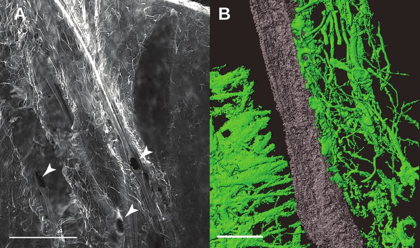
bioRxiv preprint first posted online Mar. 14, 2019; doi: http://dx.doi.org/10.1101/578542. The copyright holder for this preprint
 (which was not peer-reviewed) is the author/funder, who has granted bioRxiv a license to display the preprint in perpetuity.
                                It is made available under a CC-BY-NC 4.0 International license.

   The “sewing machine” for minimally invasive neural recording                                                                     2

   anatomical distribution of targeted electrodes. Here we address these four areas by using
   a single fine and stiff needle to insert many fine and flexible polymer electrodes, each to
   individually specified targets. The method allows us to obtain maximal device stiffness
   when penetrating into the brain while retaining maximum flexibility and minimum size
   of the indwelling implant.

   1.1. Motivation
   Improvements in areas 1-3 serve to collectively reduce the foreign body response
   (FBR); numerous studies have demonstrated that an electrode elicits a strong FBR
   when implanted in the brain [1],[2],[3],[4]. The foreign body response causes growth of
   astroglial and fibrous scar tissue, which ultimately insulates the electrode and pushes
   neurons outside the recording volume, or outright kills them [5], altogether leading to
   the electrodes failing. This FBR seems to be initiated by chemical (biocompatibility)
   and mechanical (micromotion and interfacial stress) [6],[7],[8] means; to remedy it, the
   material must be biocompatible and subject the brain to minimal mechanical stress.

   1.1.1. Mechanical stress and impedance mismatch There has been much work on
   minimizing mechanical stress; approaches include not fixing the electrode to the
   skull or dura [9],[8],[10],[11],[12],[7]; distributing stress along a long track of fine
   electrodes in “inside-out” arrays [13],[14]; distributing stress between electrodes in
   an array [15]; making the electrode flexible and inserting with a dissolving stiffener
   [16][17],[18],[1],[19],[20]; making the electrode dramatically soften upon implantation by
   coating in an elastic alginate buffer [21] or polymeric nanocomposite [4],[22]; making
   the electrode surface soft and porous [23]; increasing surface area [3]; or by adding
   sinusoidal meanders into the electrode [24],[25]. Each of these advances support the
   hypothesis that minimizing electrode-tissue mechanical stress also minimizes FBR, and
   hence should maximize electrode performance.

   1.1.2. Size Mechanical size is also important: beyond displacing less tissue, small
   implants have a smaller volume (inertia) to surface area (friction) ratio, and thus exert
   less force upon the brain during accelerations [26]. Likewise, the volume of FBR was
   shown to be proportional to device cross-sectional area [27]; polymer fibers smaller than
   6 µm show almost no FBR [28]; 12.5 µm N i − Cr − Al wires have excellent longevity
   in monkeys [13],[14]; 800 nm x 20 µm SU-8 polymer probes offer many months of
   recording stability in mice [29]; < 10 µm carbon fiber electrodes elicit reduced chronic
   inflammation [30]; carbon fiber arrays yield excellent chronic recording capability [31].
   Finally, density differences between probes and tissue, and the resulting inertial forces,
   seem to cause glial scarring [32]. This motivates us to make the electrodes as thin,
   flexible, and light as possible and to minimize the coupling between each electrode and
   dura / cranium while still allowing the electrode to be reliably implanted. Our probes
   have a density of 1.67 g/cm3 , an order of magnitude lower than tungsten, platinum,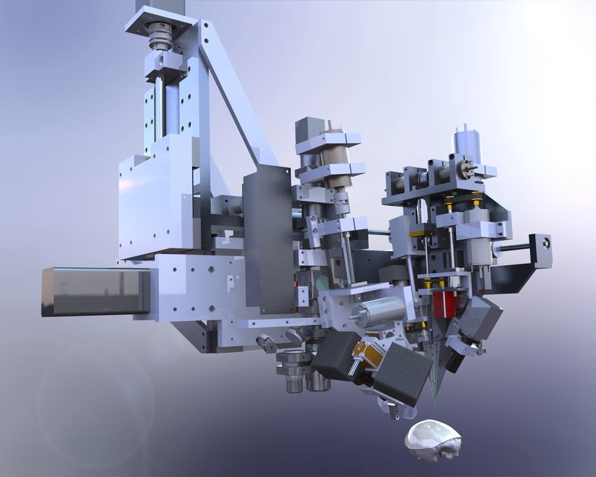
bioRxiv preprint first posted online Mar. 14, 2019; doi: http://dx.doi.org/10.1101/578542. The copyright holder for this preprint
 (which was not peer-reviewed) is the author/funder, who has granted bioRxiv a license to display the preprint in perpetuity.
                                It is made available under a CC-BY-NC 4.0 International license.

   The “sewing machine” for minimally invasive neural recording                                                                     3

   or iridium, and 5 times lower than stainless steel, and are 20,000 times more flexible
   than an equivalent commonly-used 35 µm stainless steel microwire or 35x50 µm silicon
   shank.

   1.1.3. Vasculature A second reason for recording-site failure is blood-brain barrier
   (BBB) compromise. The capillary bed in primate cortex is very dense, with
   microcapilaries spaced at 40 µm [33], and nearly a meter of vasculature per microliter
   [34], hence it is challenging to blindly implant anything without severing or collapsing
   blood vessels. While surface vasculature is redundant, and can tolerate point infarctions,
   descending arterioles are much more sensitive to disruption, and hence must be avoided
   [35]. Meanwhile, other subsurface microvasculature is more robust [36]. Ischemic
   damage due to vessel blockage can extend several hundred micrometers beyond an
   electrode shaft [37], results in hemorrhagic necrosis and edema [38], and this leads
   to highly variable responses, depending on the particular locations of vasculature along
   electrode tracts [39]. This is a prevalent problem – with a fixed silicon Utah array, 60%
   of needle tracts showed evidence of hemorrhage and 25% showed edema after a day of
   implantation [40]; with chronically implanted tungsten microwire arrays, high ferritin
   expression, indiciative of intraparenchymal bleeding, was found around a subset of all
   electrodes [41]. Indeed, the importance of BBB compromise with neural interfaces leads
   some to suggest that the glial scar is an adaptive response to maintain the BBB, and
   the ED1-reactive cells found around electrodes are partially circulatory monocytes, not
   microglia [2]. Other studies do not support the astrocyte-encapsulation hypothesis, but
   rather show that implantation is associated with prolonged BBB permeability, CD68
   immunoreactivity, and demylenation [42], and this correlates with animal to animal
   variability [43]. Either way, the weight of this evidence leads us to try to maximally avoid
   vasculature while implanting – hence, targeting one at a time under optical guidance.

   1.1.4. Targeting Targeting electrodes requires micron scale accuracy to avoid blood
   vessels, while retaining the ability to select insertion sites across the milimeter
   scale surface of the mammalian brain. For example, it would be advantageous to
   simultaneously record from neurons in different layers of the motor cortex, structures
   in the basal ganglia, and thalamus; to date, recording such structures simultaneously
   remains technically challenging [44]. In terms of neuroprosthetics, visual prostheses
   would benefit from more stimulation sites in the cortex: the user would simply be able
   to see more clearly. For recording, motor prosthesis would benefit from more electrodes,
   as there is consistent evidence that averaging over more neurons reduces decoder noise
   [45],[46],[47],[48],[49]; additionally, more end-effectors or degrees of freedom requires
   concomitantly more neurons for accurate control. Unfortunately implanting thousands
   of individually and precisely targeted electrodes, as motivated above, is difficult without
   automation.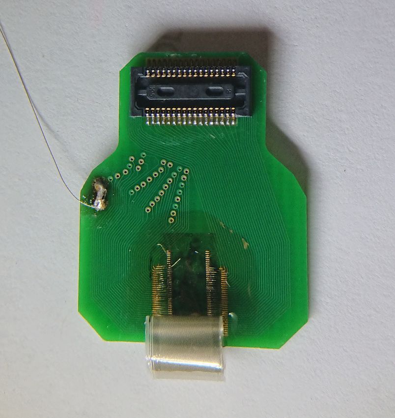
bioRxiv preprint first posted online Mar. 14, 2019; doi: http://dx.doi.org/10.1101/578542. The copyright holder for this preprint
 (which was not peer-reviewed) is the author/funder, who has granted bioRxiv a license to display the preprint in perpetuity.
                                It is made available under a CC-BY-NC 4.0 International license.

   The “sewing machine” for minimally invasive neural recording                                                                     4

   1.2. Comparison to current state-of-the art
   The sewing machine system solves a number of important practical issues: (1) Robotic
   automation of the insertion process allows each electrode to be efficiently targeted,
   while also avoiding surface vaculature. Much of the complexity of handling and
   manipulating micron-scale polymer electrodes is pushed to automation and closed-loop
   imaging & computer control (Supplemental section 8.1). (2) Wiring is managed before
   insertion (through a controlled release substrate and sequential peel-off) and after (via
   wicking silicone). Thus, the implant is the cabling, minimizing tethering forces, and
   permitting the backend to be distant from the insertion site. (3) Bonding is performed
   preoperatively, allowing the electrodes to be plated and tested beforehand. In this study,
   ultrasonic wirebonds are made to a passive adapter, but can easily be extended to active
   electronics. This has the obvious advantage of reducing surgical time / complexity. (4)
   Both the inserter needle and electrodes reside in cartridges, facilitating preoperative
   sterilization and intraoperative replacement. Integrated with the robot, this permits
   high channel count and anatomical coverage.
        There are a number of other notable approaches for minimally-invasive neural
   recording. When compared to syringe-injectable SU-8 mesh electronics [50],[51], our
   method is less invasive – rather than using a 650 µm OD glass capillary to inject, we
   use a 25 µm needle for insertion. Assuming ∼ 600 µm2 cross-sectional area as the upper
   limit of our needle and electrode, this means that one syringe injection is first-order
   equivalent to 553 needle insertions in terms of tissue disruption. Furthermore, we are
   able to avoid larger superficial vessels, which is more difficult with a large insertion
   probe. Finally, electrodes are bonded, assembled, and tested pre-operatively. However,
   our probes are not as thin and flexible as Fu et. al., and have not shown longevity and
   stability as they have [29].
        A second cutting-edge approach uses microfluidic injection of fine carbon-nanotube
   fibers [52]. This method can be less invasive in that there is no insertion shuttle; however,
   our approach should reach parity in terms of recording sites / disrupted volume when
   finer lithography permits 4 or more recording sites per probe. As with syringe-injectable
   electronics, there is an advantage here in that bonding is done pre-operatively.
        The third approach is similar to ours, albeit with a finer carbon-fiber probe, smaller
   SU-8 electrodes, and significantly better evidence of longevity and minimal scarring [53].
   A primary difference here is in scalability through robotization and fabrication; rather
   than placing the probes on the surface of the brain and carefully inserting them, our
   probes are peeled off from a pre-assembled and verified cartridge, which keeps them
   organized prior and during insertion, and allows for a larger number of insertions within
   a given time. Massey et. al. have a different approach to carbon fiber electrodes; they
   use a microfabricated silicon supports with Al/T iN coated vias and Ag ink interconnect
   to create high-density ultra-fine arrays [54].
        Further excellent results have been presented by Jason Chung et al. [20] using
   polyimide-platinum probes implanted with a stiffener and dissolving adhesive. This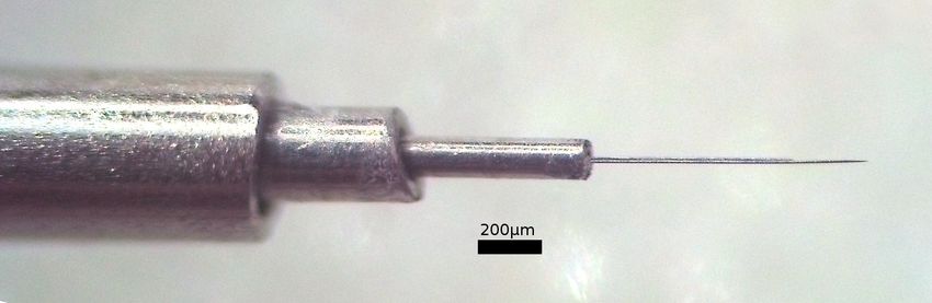
bioRxiv preprint first posted online Mar. 14, 2019; doi: http://dx.doi.org/10.1101/578542. The copyright holder for this preprint
 (which was not peer-reviewed) is the author/funder, who has granted bioRxiv a license to display the preprint in perpetuity.
                                It is made available under a CC-BY-NC 4.0 International license.

   The “sewing machine” for minimally invasive neural recording                                                                     5

                                                                      A

                                                                                 C

                                                                           B

                                                                      D

   Figure 1: Not-to-scale schematic of the “sewing machine” method for inserting fine and flexible
   electrodes into the brain. Inserter head, A, moves in three dimensions to individually pick
   flexible electrodes B from a replaceable, sterilizable cartridge C. Electrodes are then inserted
   with a fine needle D into the brain. The needle is retracted, leaving the electrode in place,
   and the inserter head moves to pick a new electrode. Electrodes and needle are enlarged to
   make them visible here.

   method has the advantage that all can be done using stereotatic equipment, and that
   recordings are stable and durable.

   2. Methods

   The ”sewing machine” system consists of three primary sub-systems: microfabricated
   electrodes, inserter needle, and inserter robot. To better understand how these
   components interact, we first provide a broad description of the basic implantation
   procedure, and then discuss each component in more detail.

   2.1. Overview of insertion procedure
   The key elements of the insertion procedure are shown in Figure 1. For in-vivo studies
   in rat, stereotaxic technique is used, and a craniotomy is performed to expose the dura
   mater (further surgical details are given below in section 2.4.1 Surgical Methods). An
   image of the surface of the brain (or agar proxy) is captured with a surface-imaging
   camera mounted to the surgical robot. Based on this image, individual target sites are
   chosen via custom software. Targeting is based on the anatomically specified target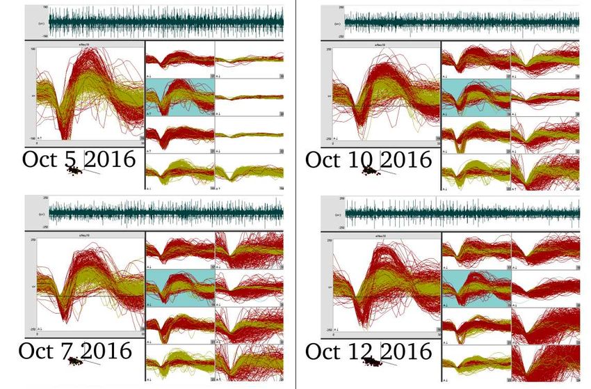
bioRxiv preprint first posted online Mar. 14, 2019; doi: http://dx.doi.org/10.1101/578542. The copyright holder for this preprint
 (which was not peer-reviewed) is the author/funder, who has granted bioRxiv a license to display the preprint in perpetuity.
                                It is made available under a CC-BY-NC 4.0 International license.

   The “sewing machine” for minimally invasive neural recording                                                                     6

   region, the desired density of insertions, and to avoid surface vasculature. Laser-
   ablation then creates targeted microdurotomies at each insertion site. Next, an electrode
   cartridge is loaded into the robot, which positions the cartridge adjacent to the selected
   target region (in rats, the cartridge is posterior to the craniotomy.) Electrodes are
   fabricated with a small loop on the end, which allows the inserter head to grasp the
   tip of an individual electrode by engaging the needle in this loop. The robot then
   peels electrodes off the cartridge, moves over the brain, and inserts them. The needle
   is then removed, leaving the electrode in place, and the process repeats. See figure 5
   for a depiction of the peel-off and insert steps. Once all electrodes in a given array are
   inserted, the reference is placed on the surface of the brain, and all loose shanks are
   protected with silicone gel. Then the PCB to which they are wirebonded is released
   from the electrode cartridge, and this PCB, to which external connectors are mounted,
   is positioned over the craniotomy and fixed in place with dental acrylic.

   2.2. Electrodes
   Arrays consisting of 64 individual electrode threads were lithographically fabricated
   using polyimide as the substrate and platinum as the conductor. Each thread has a
   single recording or stimulating site and a loop at the end, which serves as the engagement
   point for a needle that is used to position and insert the thread. Some electrodes have a
   pair of ’dog-ears’ or barbs for holding the electrode in place in the tissue. The elements
   are all shown in Figure 2 B,D. The recording or stimulating site was wired to bonding
   pads through a 4µm wide trace on a 16µm wide shank, as shown in Figure 2 C,D.
        Polyimide (PI-2610, HD Microsystems) was chosen as the electrode substrate and
   dielectric for strength (tensile strength of 350 MPa, vs 60 MPa for SU-8, 70 MPa for
   parylene-C), longevity, and biocompatibility [55].
        See Figure 3 for an illustration of the fabrication process. This begins with new
   6” p-type test grade silicon wafers. The native oxide on the silicon surface is kept
   intact in order to prevent excessive adhesion of the polyimide film to the substrate. A
   polyimide film of 2 µm is spin coated on the wafers (30s @ 500rpm, 0s @ 0rpm, 45s @
   3000rpm) and placed in a vacuum oven shortly after to cure in a nitrogen environment
   at a maximum temperature of 325 ◦C and pressure of 300 torr. Once the curing oven
   has cooled down, a bilayer of 1 µm LOR-5A resist and 1 µm i-line photoresist (OiR906-
   12) is lithographically patterned in preparation for the lift off process. Next, desalt is
   performed on polyimide by immersing the wafers in a 1:20 dilution of hydrochloric acid
   in DI water for 2.5 minutes followed by thorough rinsing in DI water and blow drying.
   Next, a platinum film 130 nm thick is deposited by electron beam evaporation. In order
   to obtain good adhesion between the metal and the polymer, a base pressure 9e-7 torr
   was achieved prior to the evaporation process. In addition, to prevent excessive heating
   of the photoresist two strategies are employed: first, ground-flat custom aluminum heat
   sinks are placed directly on the back surface of the wafers, with a thin layer of vacuum
   oil between them to provide thermal contact; second, the initial 30 nm of platinum is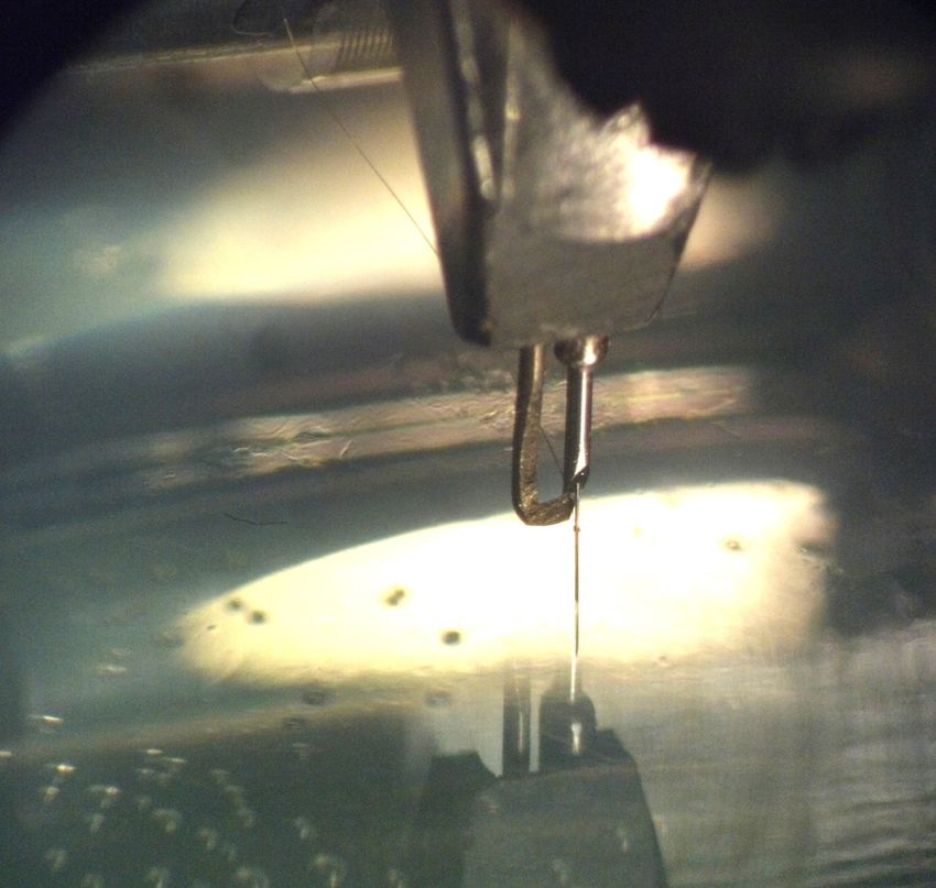
bioRxiv preprint first posted online Mar. 14, 2019; doi: http://dx.doi.org/10.1101/578542. The copyright holder for this preprint
 (which was not peer-reviewed) is the author/funder, who has granted bioRxiv a license to display the preprint in perpetuity.
                                It is made available under a CC-BY-NC 4.0 International license.

   The “sewing machine” for minimally invasive neural recording                                                                     7
                                 1
                                     A                          B              D
                                            Inverse parylene
                                              (parylene etch)

                                                Pt or Cr/Au

                                                 Polyimide
                                2                               100μm

                                                                C

                                                         Cu
                                                    plating
                                                        bus

                                3

                                     1mm                            1mm          100μm

                                 E                                        F

                                     1cm

   Figure 2: Electrodes and cartridge. A. Overview of one electrode array in the design program,
   Kicadocaml. Red is metal (Pt), gray is device outline (polyimide), green is inverted parylene
   (parylene etch). 1. Recording site and loop, detail in B. 2. Tapered electrode shank. Total
   length is 27.25 mm. 3. Bondpad area, detail in C. Bondpad size is 4.2 x 7.7 mm. To the right
   is the reference electrode, which is peeled off the electrode cartridge last by way of the large
   loop and fine forceps. B. Detail of the electrode head, showing the elongated loops, recording
   sites, and binary electrode numbering along the dog-ears. Green again is parylene – the loops
   and protrude above the parylene edge. Note also holes in parylene for electroplating. C.
   Detail of bondpad area. Large area of red-orange is the Pt/Cu bus, which supplies current to
   the wirebond sites (ovals) through 10 µm x 115 µm Pt/PI bridges. This bus is peeled away
   before releasing the electrodes from the wafer. D. Micrograph of fabricated electrodes prior
   parylene deposition. E. Photograph of electrodes, epoxied and wirebonded onto a connector
   PCB. Electrodes are curled due to stress in the parylene. F. Photograph of unpopulated
   electrode cartridge. Knife-edge, where loops are exposed, indicated with arrow.

   deposited at a high rate in order to reduce the amount of infrared energy absorbed by
   the photoresist. After metal deposition, lift off is conducted in a bath of PRS-3000
   followed by generous rinsing in DI water. Our preferred metallization scheme was Pt,
   but in some occasions an alternative Cr/Au metallization scheme was successfully used.
        After a 10 minutes dehydration bake at 120 ◦C in an oven, a second layer of
   polyimide is spin coated with the same parameters as the first one and cured at a
   maximum temperature of 450 ◦C in a nitrogen environment at 300 torr (In the event of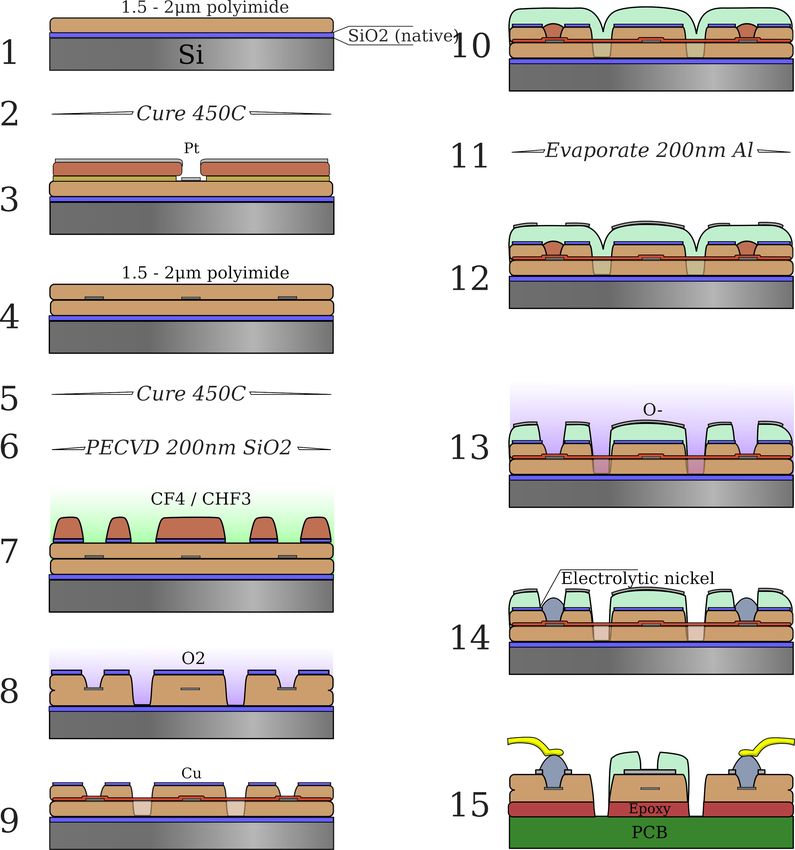
bioRxiv preprint first posted online Mar. 14, 2019; doi: http://dx.doi.org/10.1101/578542. The copyright holder for this preprint
 (which was not peer-reviewed) is the author/funder, who has granted bioRxiv a license to display the preprint in perpetuity.
                                It is made available under a CC-BY-NC 4.0 International license.

   The “sewing machine” for minimally invasive neural recording                                                                     8

   Cr/Au metallization, curing of second polyimide layer was done in two stages, first cure
   at 250 ◦C, cool down and then cure at 450 ◦C, in order to achieve optimal mechanical
   properties of the polymer films). A hard mask of silicon dioxide was used to pattern
   the polyimide. For this, a 200 nm thick SiO2 film was deposited by plasma enhanced
   chemical vapor deposition (Plasma Quest ECR PECVD System), followed by patterning
   via 2 µm g-line photoresist (OCG825-35CS). The oxide layer was etched by reactive ion
   etching (RIE, Oxide Rainbow Etcher, Lam research) and the polyimide layer was then
   etched by RIE in oxygen plasma (Plasma-Thermal Parallel Plate Plasma Etcher). This
   oxide layer is of critical importance: it serves as the weak, releasable adhesion layer
   between the parylene and polyimide, which allows electrodes to peel off without breaking
   the needle, and without prematurely falling off, e.g. when removing the electrodes from
   the carrier wafer.
        The next step is to add the copper bus, which serves as a low resistance path
   for electroplating. 400 nm of copper are deposited on the entire wafer surface and
   patterned by F eCl3 wet etch using a g-line photoresist mask. Copper is removed
   from the entire electrode and bondpad area and only left on the perimeter of the
   wafer and along a wide trace in between devices as shown in figure 2C. The copper
   bus connects to each individual Pt bondpad through a 10 µm bridge in the Pt layer
   embedded in the polyimide. Once the copper etch is completed, a 5-6 µm parylene-C
   film is deposited (Parylene deposition system 2010). A hard mask of 200 nm aluminum
   is deposited on top of the parylene by electron beam evaporation and subsequently
   overlaid with lithographically patterned g-line photophoresist. The exposed aluminum
   is then removed by wet etch in aluminum etchant (Transese, inc.) and the now exposed
   parylene is etched in oxygen plasma. After parylene etch, the aluminum hard mask is
   fully removed by wet etch, as it hinders the passage of water vapor through the film
   stack, thereby making the probes harder to remove from the carrier wafer.
        The last step is to electrochemically deposit nickel on the platinum bondpads.
   Standard photolithography with g-line photoresist is used to protect the regions of the
   wafer that do not require nickel plating. Using a custom jig, the wafer is immersed in
   Krohn Bright Nickel electroplating solution and connected to the negative terminal of
   a DC power supply. The positive terminal of the power supply is connected to a pure
   nickel anode also immersed in the solution. Electroplating is done for 15 to 20 minutes
   at 1.6 V. The photoresist is removed in an acetone bath followed by IPA and water
   rinsing. If Cr/Au metallization was used, a 5 second dip in chrome etchant is used
   to remove any chrome that may have diffused through the gold film during the high
   temperature cure.
        Devices are released from the wafer by immersing the wafer in water and peeling
   off the polyimide devices carefully with sharp tweezers. During peel off, the Pt bridges
   used for electroplating break eliminating the electrical short between pads. Devices are
   transferred from the wafer to individual glass slides and then attached to custom PCBs.
   The latter is done by applying small drops of epoxy (Epotek 353ND) on the PCB and
   then laying down the thin film device on it and allowing capillary action to distribute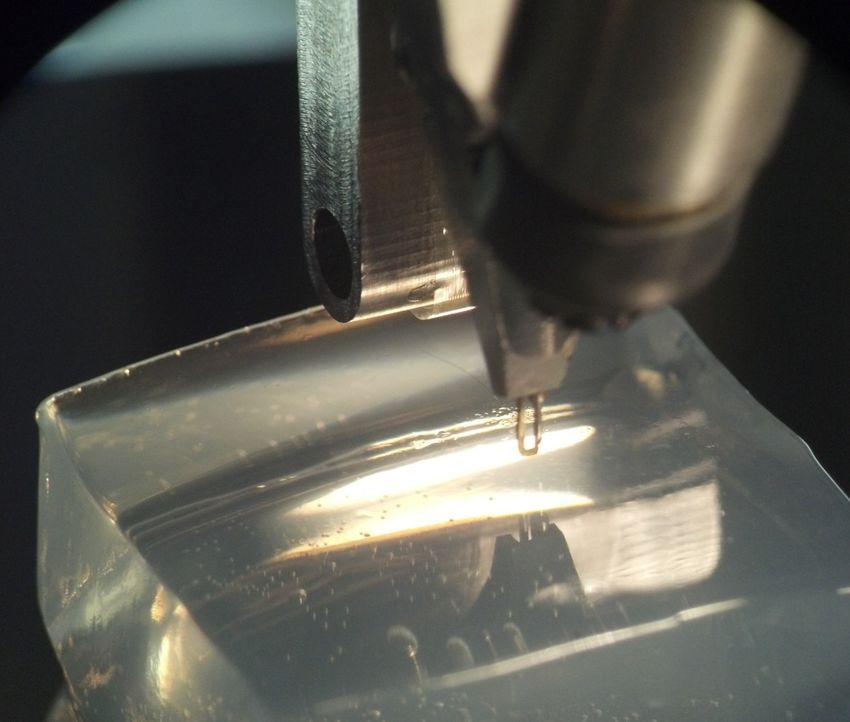
bioRxiv preprint first posted online Mar. 14, 2019; doi: http://dx.doi.org/10.1101/578542. The copyright holder for this preprint
 (which was not peer-reviewed) is the author/funder, who has granted bioRxiv a license to display the preprint in perpetuity.
                                It is made available under a CC-BY-NC 4.0 International license.

   The “sewing machine” for minimally invasive neural recording                                                                     9

   Figure 3: 1. 1.5-2 µm polyimide is spin coated over a clean, native-oxide, 6” wafer, and 2
   cured at 325 ◦C. 3. Lift-off photoresist is patterned for the conductor traces, and 130 nm Pt
   is evaporated. 4. A second layer of polyimide is spin coated, and cured 5 at 450 ◦C. 6. 200
   nm SiO2 hardmask deposited via plasma ECR and 7 patterned via RIE. 8. Device outline
   patterned using oxygen plasma. 9. 400 nm Cu evaporated for the electroplating current busses
   and patterned via F eCl3 . 10. 5-6 µm parylene deposited via the Gorham process. 11. 200
   nm Al hardmask evaporated and 12 patterned. 13. Parylene etched in oxygen plasma and Al
   is stripped. 14. Ni is electroplated to form bondpads. 15. Device released and ultrasonically
   wirebonded using Al wire.

   the epoxy within the interface. A very thin and bubble free epoxy interface is important
   to facilitate wirebonding. The nickel bumps are then connected to the gold pads on the
   PCB by aluminum wedge bonding. Lastly, marine grade epoxy is used to encapsulate
   the bondpad area and the wirebonds.

   2.3. Sewing machine and the insertion process
   2.3.1. Overview of the sewing machine device Figure 4 shows the complete sewing
   machine robot. It is composed of several key parts: an inserter head, an imaging head,
   and a set of linear drives for positioning of both relative to the stereotax and animal.
   The imaging head (A) captures high-resolution images of the cortical surface through
bioRxiv preprint first posted online Mar. 14, 2019; doi: http://dx.doi.org/10.1101/578542. The copyright holder for this preprint
 (which was not peer-reviewed) is the author/funder, who has granted bioRxiv a license to display the preprint in perpetuity.
                                It is made available under a CC-BY-NC 4.0 International license.

   The “sewing machine” for minimally invasive neural recording                                                                     10

                                                                   A
                                                                                        C                 D
                                                                                B

                                                                                                             E
                                      P
                                                              Q

                          O

                                                                                                               F
                                        N
                                                   M
                                                                                                   H
                                                          L             K
                                                                                                  I J

   Figure 4: Inserter system overview. The scull of a rhesus macaque is shown for scale. A.
   Targeting camera stack. The system uses a 1/1.2” format 2.3MP monochrome camera and a
   standard f=200 mm tube lens. B. AC servomotor and linear stepper motor for pincher θ and
   Z control. C. Ballistic retraction mechanism. D. Motor for secondary Z axes. The secondary
   cartesian axes are driven by 150W coreless motors, and are mechanically chained from the
   primary cartesian axes. E. Ballscrew for high-precision actuation of needle depth during
   insertion. F. 1x oblique microscope and 1/1.8” 5MP monochrome camera for monitoring
   electrode peel-off and insertion. H. Retractable electrode cartridge stage. This whole assembly
   moves out of the way when imaging the brain surface and targeting the insertion sites. In the
   foreground is the motor for rapid backlight retraction (silver cylinder), and the 90◦ and 45◦
   needle-electrode targeting cameras (black squares). I. Retractable backlight. During needle-
   electrode targeting, the backlight is behind the needle to regularize illumination, independent
   of surgical lighting. A 405 nm LED and diffuser is mounted to this backlight arm; polyimide
   is absorptive at this wavelength, yielding high-contrast images of the electrode loops. J.
   Needle cartridge, green, composed of four telescoping cannula. Pincher is located at an angle
   to the left of the needle cartridge. Additional lines here include air puff and saline squirt.
   K. Electrode targeting mount. This has two hybrid lead screw-stepper motors for controlling
   focus and scan of the two cameras across the electrode cartridge knife-edge. L. 2x long-working
   distance, large FOV objective for imaging the brain surface. In combination with the targeting
   camera stack A, this yields an image field of 5.4 x 4 mm. M. High power 5x objective for
   laser micro-durotomy. N. Polarizing beamsplitter for inline illumination and glare rejection.
   O. Primary X axis. These axes are driven by 400W AC servomotors with 4k encoders coupled
   to C5 grade ballscrews. P. Primary Z axis mounting point. Primary Y axis is behind laser.
   Q. Microdurotomy laser.
bioRxiv preprint first posted online Mar. 14, 2019; doi: http://dx.doi.org/10.1101/578542. The copyright holder for this preprint
(which was not peer-reviewed) is the author/funder, who has granted bioRxiv a license to display the preprint in perpetuity.
It is made available under a CC-BY-NC 4.0 International license.
The “sewing machine” for minimally invasive neural recording 11
long-working distance objective (L), to be used for micro-durotomy via the laser (Q)
and focusing objective (M). The imaging head is mounted rigidly to the primary XYZ
axes, which serves as the reference coordinate frame. Following this, the primary axes
(O,P) move the imaging head out of the way, the electrode cartridge (H) is lowered to
be posterior the craniotomy, and the inserter head (C-F,J) proceeds to peel and insert
electrodes. The inserter head is actuated via three secondary XYZ linear translation
stages, allowing dependent and relative motion to the primary axes. Details for these
steps are in the next two sections.
2.3.2. Imaging and micro-durotomy The first stage of the automated insertion process
uses the imaging head to accomplish two tasks: identification of target insertion sites
and laser-ablation to create micro-durotomies at each site. The targeting phase is
straightforward: the surgeon manually selects implantation sites via the targeting
camera, which are then translated via a calibrated offset to robot coordinates. Image
coordinates determine X and Y, while Z is controlled by focusing over the curved brain
surface. ‡
The next step is to perform microdurtomies at the insertion site. There are two
motivations for this step in place of macro-durotomies. First, manual durotomies can
result in bruising of the cortical surface. Second, in earlier studies, we have observed
post-mortem that increased intracranial pressure sometimes leads to significant cerebral
hernation through the macro-durotomy. Ultraviolet light, as is used in LASIK, is
preferred for controlled ablation of tissue; however given the difficulty of procuring
or producing a UV laser (e.g. either the 3rd or 4th harmonic of Nd:YAG), the potential
for absorption in protein-loaded CSF, and then challenge of integrating such a laser with
the robot, we chose to take a different approach: staining the dura with a red dye and
then using a green laser to perform tissue ablation.
The dura is first stained by applying 400-500 µl of saturated solution of erythrosin-
B in 0.9 N saline on the surface. Erythrosin B is a food-grade polar dye, which sticks
readily to protein; it also offers peak absorption at ∼ 524 nm, which is close to the
emission spectra of available compact frequency-doubled Q-switched lasers. Staining
is applied for 4 minutes or more, as the more highly stained the dura is, the greater
the proportion of laser energy absorbed there, and the less energy penetrates the brain.
Here we have used a 527 nm KTP-doubled Q-switched Nd:YLF laser (pulse energy 230
µJ, 1 kHz, pulse width 15 ns) for micro-durotomy; as few as 3-4 pulses are sufficient to
penetrate the dura. The green laser had a tendency to burst small blood vessels, as they
also strongly absorb green light. To minimize this effect, a 405nm, 1W diode laser was
‡ An upward-facing camera with 25 µm tungsten reticle wires is used to determine this calibration.
First, the reticle is located in the targeting camera, and then the inserter head is moved over the
upward facing camera, and the inner diameter of the needle cartridge is aligned to the reticle, thereby
transferring the optical coordinate frame to the mechanical insertion head. It is also possible to transfer
the coordinate frame from camera to robot by locating an electrode loop in the camera; when the needle
is through the loop, robot position is known in both coordinate frames.bioRxiv preprint first posted online Mar. 14, 2019; doi: http://dx.doi.org/10.1101/578542. The copyright holder for this preprint
(which was not peer-reviewed) is the author/funder, who has granted bioRxiv a license to display the preprint in perpetuity.
It is made available under a CC-BY-NC 4.0 International license.
The “sewing machine” for minimally invasive neural recording 12
A B C D E
Figure 5: A. Needle is threaded through the electrode loop, which is exposed past the knife-
edge of the electrode cartridge. B. The needle-pincher peels the electrode off the parylene
backing sheet which is glued (Zap thin wicking cyanoacrylate) to the electrode cartridge. In
this figure, electrodes are being inserted into a 0.6% w/v agarose tissue proxy. The pincher
is used to prevent the electrode from falling off the needle, and to support the needle and
electrode so the needle does not bend during rapid peel-off. C. The needle and electrode are
moved over the target site, and the pincher is slightly retracted to act as a pulley to keep the
electrode from slicing laterally into the brain. D. The needle is lowered to drive the electrode
to its anatomical target. E. The needle is retracted, the pincher moves out of the way, and
the process repeats.
coupled into the beampath via a dichroic; this wavelength is near the peak hemoglobin
absorption, and served to cauterize any resultant small bleeds.
The surface imaging camera uses 590 nm illumination from a set of LEDs (not
shown in figure 4), which is within the hemoglobin absorption band, but outside the
erythrosin-B absorption – hence the vessels remain clearly visible even in the presence
of the dye. Polarization is used to reduce glare from saline meniscus; illumination
polarization is perpendicular to light transmitted by the polarizing beamsplitter in the
targeting camera stack, hence most imaged photons are scattered. See supplemental
figure 11 for a depiction of the imaging system.
2.3.3. Automated insertion Once insertion targeting and microdurotomies are
complete, the imaging head moves out of the way, the electrode cartridge stage is
lowered, and electrodes are inserted. The insertion process is illustrated in Figure 5.
First, needle step depth and orientation is calibrated so that the step is slightly out
of the 34 gauge cannula, and oriented facing away from the knife-edge, so that it can
optimally engage with the electrode loops; see supplemental Figure 12 for an image of the
needle step. This calibration needs to be done once per needle; the needle cartridge itself
may be independently sterilized and replaced before and during a surgery. Then, for
each electrode, the needle is threaded through the loop. The control software (described
in the supplemental section 8.1 Software) positions the needle within the view of the two
electrode targeting cameras (Figure 4 I,K) and uses computer vision to guide it through
the loop. Next, the pincher (a 90◦ bent piece of 50 µm W wire) is rotated around
to pinch the electrode to the lower needle cannula (34 gauge, 150µm outer diameter).
This is an important step, as it buffers the needle from the stress of peel-off – the set
of needle-electrode motions that separates the polyimide electrodes from the parylene
backing sheet – thereby keeping the needle from bending. As such, the degree adhesion
between the parylene and polimide is critical during peel-off, as described in sectionbioRxiv preprint first posted online Mar. 14, 2019; doi: http://dx.doi.org/10.1101/578542. The copyright holder for this preprint
(which was not peer-reviewed) is the author/funder, who has granted bioRxiv a license to display the preprint in perpetuity.
It is made available under a CC-BY-NC 4.0 International license.
The “sewing machine” for minimally invasive neural recording 13
2.2 Electrodes above. The peel-off maneuver leaves ∼ 20mm of electrode lead freely
floating in air so that insertion can proceed under minimal tension. The inserter head
then moves to the target site, whose coordinates are determined in the imaging phase
above. The pincher moves slightly out of the way to act as a pulley for the electrodes
as they are inserted, ensuring the threads followed the needle path, rather than cutting
laterally into the tissue. The needle then drives the electrode into the brain through
the micro-durotomy. Then bursts of air or saline from embedded cannulae (4J) may be
used to lay the electrode threads onto the surface of the dura. The needle then retracts
with high acceleration and jerk using the ballistic retraction mechanism (Supplemental
Section 8.3). This serves to keep the electrodes from coming out with the needle, or
from buckling and being driven laterally into tissue as the needle retracts, both which
are otherwise significant problems. With the needle retracted, the inserter head moves
back over the electrode cartridge to target the subsequent loop in the array.
2.4. In vivo demonstration
For an in-vivo demonstration of this system, we used adult male long-evans rats, 300-
500g. All procedures were performed with approval of the University of California, San
Francisco Institutional Animal Care and Use Committee and were compliant with the
Guide for the Care and Use of Laboratory Animals.
2.4.1. Surgical methods First, rats are anesthetized with 4% isoflurane in oxygen, their
skin cleaned in betadine and sterile saline, and an incision is made along the midline
to expose the cranium. After incision, isoflurane is lowered to ∼2%. Temperature is
maintained at 38 ◦C with a heating pad. The cranium is scraped and cleaned with
3% hydrogen peroxide, and abioRxiv preprint first posted online Mar. 14, 2019; doi: http://dx.doi.org/10.1101/578542. The copyright holder for this preprint
(which was not peer-reviewed) is the author/funder, who has granted bioRxiv a license to display the preprint in perpetuity.
It is made available under a CC-BY-NC 4.0 International license.
The “sewing machine” for minimally invasive neural recording 14
PCB, as mentioned in Section 2.2. Impedance measurement was performed using a
32-channel TDT IZ2 stimulator using manufacturer supplied software.
2.4.3. Histology Animals were deeply anesthetized with an overdose of Euthasol and
perfused intracardially with heparinized phosphate-buffered saline (PBS), followed by
fixation in 4% paraformaldehyde in PBS, pH 7.4. In animals in which the electrode cap
came off (or was removed) prior perfusion (#13 - 19d, #14 - 14d, #11 - 39d)) brains
were extracted on the same day and postfixed in fixative overnight. For animals with the
head mount intact (#12 - 29d, #16 - 72d, #17 - 25d) brain extraction was performed in
several steps so that that implanted electrodes were not pulled out or displaced during
the procedure. First, brains were partially exposed on a ventral side and placed in
fixative overnight at 4 ◦C. In a following day the remaining skull bone, acrylic and other
parts of implant were carefully removed under a dissecting microscope using a dental
drill and microsurgical tools; electrode threads were cut about 1 mm above the brain
surface with microscissors leaving inserted parts in the brain undisturbed. Extracted
brains with threads were immersed in 30% sucrose for 5-6 days at 4 ◦C and frozen at
−20 ◦C for cryosectioning. Coronal 50-80 µm thick serial sections were cut on a cryostat
(Microm, Thermo Fisher Scientific), and collected in 12-well plates filled with PBS.
To reveal changes in neuronal tissue in response to the implantation procedure,
sections representing surgical areas were stained using a routine Nissl staining (0.1%
Cresyl Violet). To show changes in glial cells (astrocytes) sections were immunolabeled
for GFAP (glial fibrillary acidic protein). Briefly, free-floating sections containing regions
of interest with flex electrodes were permeabilized with 50% ethanol for 10 min and
rinsed in PBS. Sections were then blocked with 10% normal donkey serum in PBS
for 30 min and incubated for 48 hrs at 4 ◦C on an orbital shaker with a primary anti-
GFAP antibody, (mouse mAb Sigma-Aldrich, 1:1,000 ) diluted in PBS containing 0.05%
Triton X-100. Next, sections were washed in PBS, incubated with 2% normal donkey
serum for 10 min, and incubated for 4 hrs with the secondary Alexa Fluor 488-labeled
donkey anti-mouse antibody (1: 300) for immunofluorescence. For immunoperoxidase
staining, sections were initially incubated in 3% hydrogen peroxide/PBS for 10 min to
quench endogenous peroxidase activity, then processed as above, until the secondary
antibody step, which was the incubation in biotinylated donkey anti-mouse antibody
(1:500, Jackson Immunoresearch) for 4 hours, followed by rinses in PBS and incubation
in ExtrAvidin (Sigma-Aldrich, 1:5,000) for 4 hours. Peroxidase was detected using
diaminobenzidine (Sigma-Aldrich). Sections were rinsed, mounted on gelatin-coated
slides, air-dried, dehydrated in graded alcohols, cleared in xylene and coverslipped
with D.P.X. mounting media (Sigma-Aldrich). After immunofluorescence, sections
were rinsed in PBS and coverslipped using ProLong Gold Antifade mountant medium
(Thermo Fisher Scientific). Images were acquired using laser confocal microscope
LSM510 Meta (Carl Zeiss Microscopy, LLC) and Nikon Eclipse 90i wide-field microscope
(Nikon Instruments Inc)bioRxiv preprint first posted online Mar. 14, 2019; doi: http://dx.doi.org/10.1101/578542. The copyright holder for this preprint
(which was not peer-reviewed) is the author/funder, who has granted bioRxiv a license to display the preprint in perpetuity.
It is made available under a CC-BY-NC 4.0 International license.
The “sewing machine” for minimally invasive neural recording 15
3. Results
We have repeatedly and reliably implanted our thin, flexible electrodes in both agarose
tissue proxy and the brains of rats (Figure 6). In Figure 6B, note that the individual
threads form a single ”rope” that loops up to the PCB and connector assembly. This
formation results from capillary action. Provided the free length of electrode is not
too long and is constrained during peel-off and insertion, capillary action allows the
electrodes to remain both reasonably well organized and mechanically isolated when
affixing the connector to the scull.
Regarding reliability, insertion into agar is consistent and repeatable; reliability
in-vivo is limited by surgical factors, mainly: blood occluding the surgical site, blood
clogging the needle cannula, microdurotomy quality, needle durability, and implant
durability. More explicitly: avoidance of blood vessels keeps the sugical site clean,
which allows for accurate targeting of subsequent insertions. If a vessel is inadvertently
hit, blood tends to spread to form a subdermal hematoma, occluding future insertions;
some of this blood will leak to the surface, which can wick up the needle guide-cannula
and clot, potentially causing the needle to seize. Likewise, if a microdurotomy is too
deep, subsurface capillaries may be ruptured, again occluding the surface and possibly
contaminating the needle cannula; if it is too shallow, sufficient dura may remain to
buckle the needle, forcing replacement. Nonetheless, most surgeries were done with care
and with one needle. Finally, as with many other approaches, implant durability is
limited by the bone-screw’s attachment on the growing and flexible rat cranium; this
failure mode is shared with other approaches.
Because the whole insertion process is automated and the robot can move quickly,
per-thread insertion times were quite short. Indeed, other than the needle insertion,
which is performed at 0.1-2 mm/s, robot movements are rapid, up to 100 mm/s. This
allows for the per-thread insertion cycle times of less than 9 seconds (supplementary
video 1). Such rapid insertion allows for large numbers of electrodes to be inserted in a
practical surgical timeframe.
3.1. Histology
In animals in which electrodes were removed prior fixation, examination of sections
stained with Cresyl Violet and GFAP immunohistochemistry has revealed multiple
penetration lesions (Figure 7 A,B). In vivo insertions resulted in a different pattern from
what might be the expected after the agarose insertion of Figure 6. Although most of
the penetration lesions were generally in downward direction, these varied significantly
in their size, shape and exact orientation (arrowheads in Figure 7, tracks #1-7 in 8
A). Some spanned all cortical layers and could be followed into the white matter and
subcortical structures, whereas others were more oblique and ended more superficially
in depth (not shown). The majority of lesions were wider near the cortical surface
and narrower at the deeper end becoming to be about 50 µm wide. Some lesions were
larger, up to 1-2 mm wide (Figure 7A,B, lesion #7). Furthermore, several adjacentbioRxiv preprint first posted online Mar. 14, 2019; doi: http://dx.doi.org/10.1101/578542. The copyright holder for this preprint
(which was not peer-reviewed) is the author/funder, who has granted bioRxiv a license to display the preprint in perpetuity.
It is made available under a CC-BY-NC 4.0 International license.
The “sewing machine” for minimally invasive neural recording 16
A B
Figure 6: Examples of insertions. A. Early result showing 20 insertions into 0.6% w/v agarose
tissue proxy. Electrodes were in two rows; bubbles are from the halogen lights used in the
test. B. Image showing 42 electrodes inserted into the somatosensory cortex of a rat (#10).
One needle was used.
lesions were seen as merged at the top forming one large area of the eroded layers I-
II (asterisks in Figure 7 A,C). The tissue in subcortical penetrations such as in the
dorsal hippocampus were less affected (not shown). To estimate more accurate position
of inserted threads and especially the location of the recording sites, brains in two
animals were extracted and cryosectioned with electrodes remaining in situ (Figure
7 C,D). Microscopic examination has confirmed that tissue sections had the ability to
retain fragments of implanted electrodes without displacement even after cryosectioning,
thawing and immunostaining. Most electrodes had recording sites in deeper layers V and
VI which as had less tissue damage and consistently showed more normal morphology
than upper layers (Figure 7 C); as shown in Figure 7, D1-D4 recording parts of the flex
electrodes in layer V were surrounded by neuronal perikarya with normal appearance.
Few electrodes were found to be inserted very obliquely with recording sites in layers
II and III (e.g. Figure 8 A). All lesions had little or no surviving neuronal cells at its
core and increased density of non-neuronal cell (e.g. densely filled core of the lesion
#7 as shown in Figure 7 A); these were morphologically identified as granulocytes
(neutrophils), monocytes (macrophages), microglial and astrocytic cells (not shown).
GFAP (an astrocytic marker) was upregulated in all examined animals, and expressed
at higher levels at the insertion sites (Figures 7 B, 8 A), and in upper layers (8 A). High
resolution microscopy revealed dense plexuses of GFAP-positive astrocytes that were
lining up the space around the implant cavity (Fig 8 A); astrocytic processes were also
in a direct contact with the implant material (Fig 8 D).
3.2. Electrophysiology
During the course of device testing and refinement, we performed extracellular
recordings from four rats (rat #5, #13, #15, #16); other animals were used for devicebioRxiv preprint first posted online Mar. 14, 2019; doi: http://dx.doi.org/10.1101/578542. The copyright holder for this preprint
(which was not peer-reviewed) is the author/funder, who has granted bioRxiv a license to display the preprint in perpetuity.
It is made available under a CC-BY-NC 4.0 International license.
The “sewing machine” for minimally invasive neural recording 17
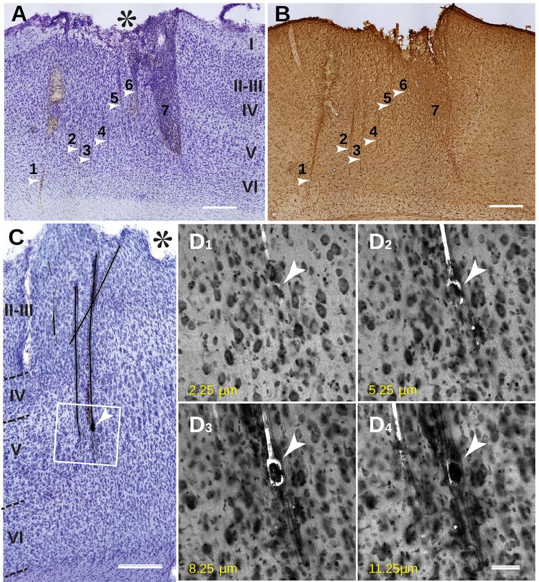
Figure 7: Histological changes in the cortex after sewing. A,B show cortical tissue response
in an animal implanted for 2 weeks. C,D show the response after 10 weeks of implantation.
A. Cresyl Violet (Nissl) staining show presence of insertion lesions (arrowheads), numbered
1-7; roman numerals I-VI indicate cortical layers; Note a much large lesion # 7 filled with
non-neuronal cells, also lesions 5, 6, and 7 and likely more have merged at the top and
formed a large necrotic cavity (asterisk). B. Same as in A lesions are also seen with GFAP
Immunoperoxidase (#1-7, arrowheads) on the adjacent section. Scale bar: A, B 500 µm C.
Two vertically oriented and near parallel electrodes and one smaller fragment going across.
The tissue damage was noticeably larger in superficial layers I-III (asterisk) and much lesser in
layer V, which contained the recording site (arrowhead). Boxed area is scanned with a confocal
microscope and shown in D1-4 to demonstrate that those electrodes were not merely stuck
to the surface of the section but were inside the tissue. D.1-4: Consecutive confocal images
from the boxed area representing a 3 µm step depth using confocal imaging in 488 nm laser
and 80/20 neutral beamsplitter. This also reveals a tissue cavity that contains the implant as
well as a more accurate relative position of neuronal cells bodies (seen as dark profiles) near
the recording site (arrowhead on D1-D4). There are many neurons in within 10-20 µm of the
immediate vicinity of the recording site Scale bar C, 250 µm, D1-D4, 50 µm.bioRxiv preprint first posted online Mar. 14, 2019; doi: http://dx.doi.org/10.1101/578542. The copyright holder for this preprint
(which was not peer-reviewed) is the author/funder, who has granted bioRxiv a license to display the preprint in perpetuity.
It is made available under a CC-BY-NC 4.0 International license.
The “sewing machine” for minimally invasive neural recording 18
Figure 8: A. Area with implants (arrowheads) in the layer III showing upregulation of GFAP
immunofluorescence, especially near the electrodes. Arrowheads point to electrode fragments
with recording sites. B. 3D reconstruction of high resolution confocal images of the GFAP-
immunoreactive processes from the same tissue as in A. Note areas of possible direct contact
between the implant and astrocytic processes (arrows), and the relative preference of the
astrocytes for one side of the electrodes. Unknown if this was the SiO2 (hardmask) coated
side, or the polyimide side. Scale bars: A, 250 µm; B, 25 µm.
and insertion testing and refinement Data from rats #5 and #16 are shown in Figure
9. Rat #16 had 24 implanted electrodes that were recorded over 2 months. We
observed single-unit action potentials on 39% of the implanted electrodes overall: 3
of 22 electrodes for rat #5; 2 of 13 electrodes for rat #13; 7 of 12 electrodes for rat #15;
and 16 of 24 electrodes for rat #16. Rats #5, #13, and #15 had their implant fall off
prematurely, and did not last as long as #16.
Figure 9 shows electrode impedance, as measured with our TDT system, from
one rat (#16) implanted with 24 electrodes. Of the bank of 32, 8 electrodes (gray)
were not implanted and cut off above the brain; these serve as a control. Note the
TDT system cannot report or measure impedances > 1M Ω, so control impedances are
qualitative. Implanted electrodes were plated down to ∼ 100kΩ prior implantation with
platinum black (chloroplaticinc acid + lead acetate, −2µA, 60 s). Electrode impedance
of the implanted electrodes gradually increased with time, consistent with the platinum
black flaking off; impedance of the control electrodes gradually decreased, consistent
with the connector, encapsulant epoxy, or polyimide absorbing water. Despite changes
in impedance, recording quality was relatively constant over the implant period, with
some waveforms stable up to a week.bioRxiv preprint first posted online Mar. 14, 2019; doi: http://dx.doi.org/10.1101/578542. The copyright holder for this preprint
(which was not peer-reviewed) is the author/funder, who has granted bioRxiv a license to display the preprint in perpetuity.
It is made available under a CC-BY-NC 4.0 International license.
The “sewing machine” for minimally invasive neural recording 19
A B
900
800
C 33
35
37
34
36
38
18
16
D E
39 40
700 14
41 42
600
Impedance (kΩ)
43 44
12
Number of channels
45 46
500 47 48 10
49 50
suA
400 8 muA
51 52
53 54
300 6
55 56
200 57 58
4
59 60
100 61 62 2
63 64
0 0
6 16 16 16 16 16 16 16 16 16 16 16 16
/1 / / / / / / / / / / / /
/1 16
10 14/ 6
10 17/ 6
10 19/ 6
10 2 1/ 6
10 2 4/ 6
10 26/ 6
/2 16
/3 16
/ 6
3 6
/ 6
10 /5/ 6
10 10/ 6
11 16/16
11 18/16
11 21/16
11 23/16
/2 6
16
11 2/16
11 4/16
11 7/16
11 11/16
11 14/16
28 0/3 /10 /14 /19 /24 /28 1/2 1/7 /11 /16 /21 /28
/ 1
/ 1
/ 1
/ 1
/ 1
/ 1
11 1/1
9/ 8/1
10 0/1
10 3/1
/ 1
11 9/1
9/
10 2/
10 8/
8/
1 10 10 10 10 10 1 1 11 11 11 11
2
/
/
/
9/
/
/
/
/
/
/
Record date Record date
Figure 9: Representative electrophysiology. A. Example single-unit, showing PCA, voltage
waveform, and inter-spike-interval distribution. This was the first ’spike’ recorded with the
system. B. Raw voltage trace from the same rat (#5). C. Evolution of electrode impedances
in rat #16. Gray are unimplanted control electrodes, cut off above the brain. D. Recording
quality over time. SUA = single unit activity, easily sortable. MUA = multi-unit activity, not
sortable. E. Example waveforms over one week showing stability.
4. Discussion
Cerebral cortex is a complex laminar structure consisting of dense layers of neuronal
and non-neuronal cells and a thick layer of myelinated fibers underneath; it is covered
with layers of protective membranous connective tissue; and finally, it contains a dense
network of capillaries under considerable hydraulic pressure [56]. All these factors are
contribute to cortical firmness and elasticity, hence it is no surprise that cortical insertion
resulted in a heterogeneous pattern of implantation. The histological assessment has
revealed that proximity to the surface was the most influential factor in the tissue
response; the damage was strongest at the cortical layer I and II and dissipated in the
deeper tissue, thus placing the priority for the sewing method more on reducing the
amount of injury to upper cortical layers. It is not clear what exactly have caused such
damage; on one hand, it might be caused by surgical procedures such as durotomy – or
dimpling-related damage to pia and to capillary branches below the pia, which are much
more numerous in layers I-III [34]. Another significant consequence of sewing on the
tissue condition was presence of large penetrating lesions that were clearly associated
with insertion process. It is also likely that the inserter needle can inflict a more
significant injury by accidentally stabbing a larger blood vessel such as a penetrating
arteriole on its way [57]. Overcoming these technical problems and improvements to
the surgical techniques are underway. Because the damage to deeper cortical layers and
subcortical structures appears minimal, it has also demonstrated a potential for using
flexible electrodes in a chronic long-term recording experiments especially for subcorticalbioRxiv preprint first posted online Mar. 14, 2019; doi: http://dx.doi.org/10.1101/578542. The copyright holder for this preprint
(which was not peer-reviewed) is the author/funder, who has granted bioRxiv a license to display the preprint in perpetuity.
It is made available under a CC-BY-NC 4.0 International license.
The “sewing machine” for minimally invasive neural recording 20
structures.
Overall, sewing had shown three general sources of tissue damage:
(1) The superficial damage possibly due to severing pial blood supply or other
factors. This might have triggered neurodegeneration and cell death in upper cortical
layers; it may also cause tissue swelling and herniation, thus unpredictably changing
electrode placement.
(2) Localized and contained penetrating lesions, occasionally large, up to 500
µm wide inflicted by the direct mechanical movement of the needle. This causes sparse
cell loss and scarring in the vicinity of the track, and possibly reduced neuronal activity
at the recording site.
(3) Highly localized and contained reaction of the tissue to the presence of implant,
such as tissue cavitation around the implant and local glial activation. There is no data
to support that this may case neuronal loss, but it might affect electrical properties in
the recording site.
It is very likely that the vasculature damage overwhelms all other factors, making
lesions much larger by cutting blood supply and by triggering the migration of
inflammatory cells such as neutrophils and monocytes (macrophages) into the area.
Nevertheless, as evident by a better preserved deeper layers and subcortical
structures, small and flexible implants can benefit a long-term implantation outcome;
however, the insertion procedure must be better guided at the microscale level to avoid
impacting descending vessels. Future work can focus on improving this targeting,
perhaps with OCT imaging and more degrees of freedom on the inserter head, as well
as further miniaturizing the needle and electrodes, and lithographically patterning more
electrode contacts per shank.
4.1. Conclusion
We have demonstrated that the sewing machine approach is effective in recording
extracellular neural activity in rodents, and is worthy of further study and development.
5. Acknowledgements
TLH would like to acknowledge the generous help of Eric R. Hanson in the machining
and design of five different revisions of the inserter robot, Keenan M. Hanson for advice
and help with metallurgy, Jasmine Amerasekera for fabricating the needles, David Piech
for helpful discussions of surgical planning, Jason Chung, Hannah Joo, Daniel Liu and
others from the Loren Frank lab for vital instruction and help with surgical technique,
Lindsey Presson with surgical assistance, and Joseph Makin and Joseph O’Doherty for
helpful scientific discussion.
This work was supported by DARPA Contract W911NF-15-2-0054 from the
Biological Technologies Office (BTO). The views, opinions, and/or findings contained
in this material are those of the authors and should not be interpreted as representingYou can also read