3D Fabrication of 2D Mechanisms
←
→
Page content transcription
If your browser does not render page correctly, please read the page content below
EUROGRAPHICS 2015 / O. Sorkine-Hornung and M. Wimmer                                                                  Volume 34 (2015), Number 2
(Guest Editors)

                                     3D Fabrication of 2D Mechanisms

                                                               Jean Hergel and Sylvain Lefebvre

                                                                  Inria Nancy Grand-Est, France

                                               n0

                                                    n2

                                               n1
                                      (a)                (b)                       (c)                         (d)                           (e)
Figure 1: Our algorithm takes as input a 2D design of a mechanism (a) and produces a 3D model (c) by computing a layout
encouraging inclusion between parts, formulating the layout as a graph orientation problem (b). In the graph, edge orientation
indicates inclusion relationships. The 3D model can be printed (c,d) and is functional. The chassis is automatically synthesized.

        Abstract
        The success of physics sandbox applications and physics-based puzzle games is a strong indication that casual
        users and hobbyists enjoy designing mechanisms, for educational or entertainment purposes. In these applications,
        a variety of mechanisms are designed by assembling two-dimensional shapes, creating gears, cranks, cams, and
        racks. The experience is made enjoyable by the fact that the user does not need to worry about the intricate
        geometric details that would be necessary to produce a real mechanism.
        In this paper, we propose to start from such casual designs of mechanisms and turn them into a 3D model that can
        be printed onto widely available, inexpensive filament based 3D printers. Our intent is to empower the users of
        such tools with the ability to physically realize their mechanisms and see them operate in the real world.
        To achieve this goal we tackle several challenges. The input 2D mechanism allows for some parts to overlap during
        simulation. These overlapping parts have to be resolved into non–intersecting 3D parts in the real mechanism.
        We introduce a novel scheme based on the idea of including moving parts into one another whenever possible.
        This reduces bending stresses on axles compared to previous methods. Our approach supports sliding parts and
        arbitrarily shaped mechanical parts in the 2D input. The exact 3D shape of the parts is inferred from the 2D input
        and the simulation of the mechanism, using boolean operations between shapes. The input mechanism is often
        simply attached to the background. We automatically synthesize a chassis by formulating a topology optimization
        problem, taking into account the stresses exerted by the mechanism on the chassis through time.

1. Introduction                                                                    context, where efficiency and reliability of the created mech-
                                                                                   anisms is the top priority.
Designing and modeling mechanisms is a difficult, highly
technical task. Therefore significant research effort is ded-                         However, there are many indications that casual design-
icated to automate their generation. For instance, the most                        ers and hobbyist actually enjoy designing mechanisms, from
advanced techniques are capable of synthesizing complex                            the video games The Incredible Machine (Dynamix, 1993)
trains of gears and cams [ZXS∗ 12], produce mechanical                             and Crayon Physics Delux (Hudson Soft) to physics sand-
automatons from (virtual) animated characters [CTN∗ 13,                            box applications such as Garry’s mod (Facepunch Studios),
CLM∗ 13, TCG∗ 14], or generate functional designs with                             Phyzicle (by A. Shirinian) and Algodoo (Algoryx). Using the
hinges and slides from a high level specification [Koo14].                         later, thousands of users create and share intriguing mecha-
This is a very important trend of research in a professional                       nisms modeled in two dimensions. These are used for educa-

 c 2015 The Author(s)
Computer Graphics Forum c 2015 The Eurographics Association and John
Wiley & Sons Ltd. Published by John Wiley & Sons Ltd.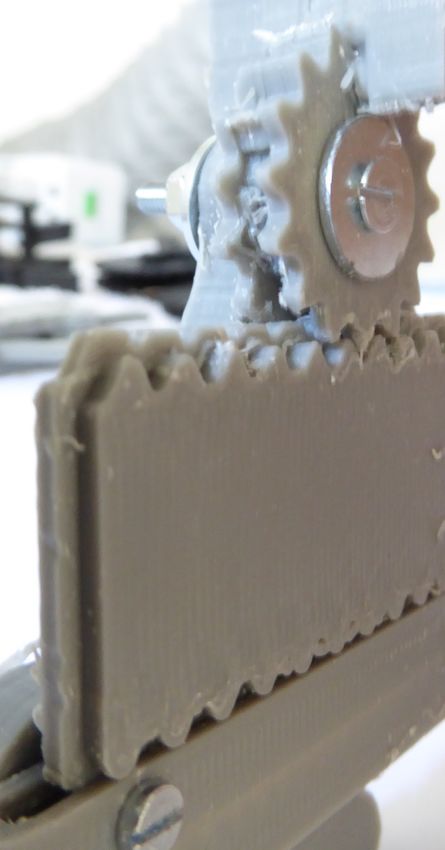
J. Hergel & S. Lefebvre / 3D Fabrication of 2D Mechanisms

tional and entertainment purposes, but are accurate enough
for early prototyping of small mechanisms.
   In this paper, we seek to fabricate real mechanisms that
can be 3D printed on inexpensive filament printers, starting
from an underspecified two-dimensional model of a mecha-
nism. Our goal is to empower casual mechanism designers
— kids, teachers, hobbyists — with a way to bring their de-
signs to reality, without having to go through the tedious and
                                                                       Figure 2: Possible solutions for the example of Figure 1.
difficult modeling process required for fabrication.
                                                                       Left: Print out of our result using layering only. Middle:
   The input to our algorithm is the unmodified output of a            Out-of-plane motion resulting from using layering. Right:
popular physics sandbox, in this case Algodoo (Algoryx). It            Print out of our result using inclusion. It produces less out-
contains the 2D geometry of the mechanical parts, the spec-            of-plane motions as axles are connected on both extremities.
ification of joints (hinge, fixed), and information regarding
which parts can interact during simulation and which are               • We automatically synthesize a chassis for the mechanism
allowed to move across each others. The output of our al-                using topology optimization. Our approach takes into ac-
gorithm is a mesh ready for fabrication on a fused filament              count the forces generated by the mechanism on the chas-
fabrication printer.                                                     sis during the entire simulation.
   To achieve our goals, we have to tackle several challenges.            Our approach makes no assumption regarding the shape
First, the mechanism functions in two-dimensions by allow-             of the mechanical parts: gears, cranks and cams are not
ing some parts to overlap. We have to produce a 3D model               tagged in the input. They function properly through the
where these collisions do not occur, ensuring that the cor-            preservation of the set of contacts and interactions from the
responding 3D parts are never in contact. Conversely, some             2D mechanism into the fabricated mechanism.
contacts are exploited by the mechanism, allowing parts to
interact to produce gears, cams, and sliding motions. These            Limitations Our algorithm does not detect unrealistic
interactions have to be preserved within the final mechanism.          mechanisms (i.e. mechanisms that may generate excessive
Second, the two-dimensional specification of the parts is in-          stresses, that may exhibit singularities, or mechanisms where
complete: The final 3D shape of each part has to be deduced            parts can fall or detach). Some over-constrained 2D designs
from the simulation of the mechanism. This often involves              cannot be resolved by layering or inclusion (Section 4.6).
producing parts with a complex profile in depth allowing
other parts to slide within or along them. Finally, the mech-          2. Previous work
anism has to be enclosed and supported by a chassis, which             Modeling objects for 3D printing is a challenging and tech-
acts as the ground body. This chassis is typically missing             nical task, as many constraints from the physical world and
from the specification and has to be automatically generated.          the printing process have to be considered. Thus, a recent
   3D printed mechanisms are very sensitive to bending                 trend of research proposes novel algorithms to help design-
stresses, in particular orthogonally to the material deposition        ers identify and fix problematic geometries, for instance
direction. Consider the model of Figure 1, for which two               making objects stronger [SVB∗ 12] or ensuring that designs
possible fabricated solutions are shown in Figure 2. If the            are properly balanced [PWLSH13, BWBSH14]. Algorithms
parts are layered next to each others the wheel tends to move          have also been proposed to fabricate articulated [BBJP12,
out of its plane (Figure 2, middle): the moving parts are at-          CCA∗ 12] or deformable characters [STC∗ 13] from their vir-
tached to one extremity of their axles and bending stresses            tual counterparts. This typically involves optimizing the ge-
produce out-of-plane motions, an effect that cumulates on              ometry and automatically modeling joints or internal struc-
all axles. This is worsen by the necessary tolerances between          tures to achieve the desired degrees of freedom.
moving parts and axles. To reduce this issue our mechanisms               Several approaches focus specifically on mechanisms.
exploit both layering and inclusion (Figure 2, right). When            The work of Zhu et al. [ZXS∗ 12] proposes to automati-
parts include one another, the bending stresses are absorbed           cally generate a mechanism producing a desired motion on
on both extremities of the axles, reducing out-of-plane mo-            multiple rigid objects, typically an animated toy. The mecha-
tions and avoiding to propagate bending stress to other axles.         nism is hidden in a box below the object. The work of Coros
                                                                       et al. [CTN∗ 13] automatically generates a mechanism in-
Contributions                                                          side an already articulated model so as to reproduce an an-
• We solve for the 3D layout of the mechanism by exploit-              imation sequence. Duygu et al. [CLM∗ 13] embed mecha-
  ing inclusions whenever possible.                                    nisms called oscillation modules inside an articulated char-
• We define the 3D shapes of the final parts by construc-              acter. The oscillation modules are optimized to reproduce a
  tive solid geometry (CSG), considering the positions of              target animation. Koo et al. [Koo14] automatically produce
  the parts throughout the mechanical simulation.                      articulations in a design, from a high level specification of

                                                                                                                                   c 2015 The Author(s)
                                                                  Computer Graphics Forum c 2015 The Eurographics Association and John Wiley & Sons Ltd.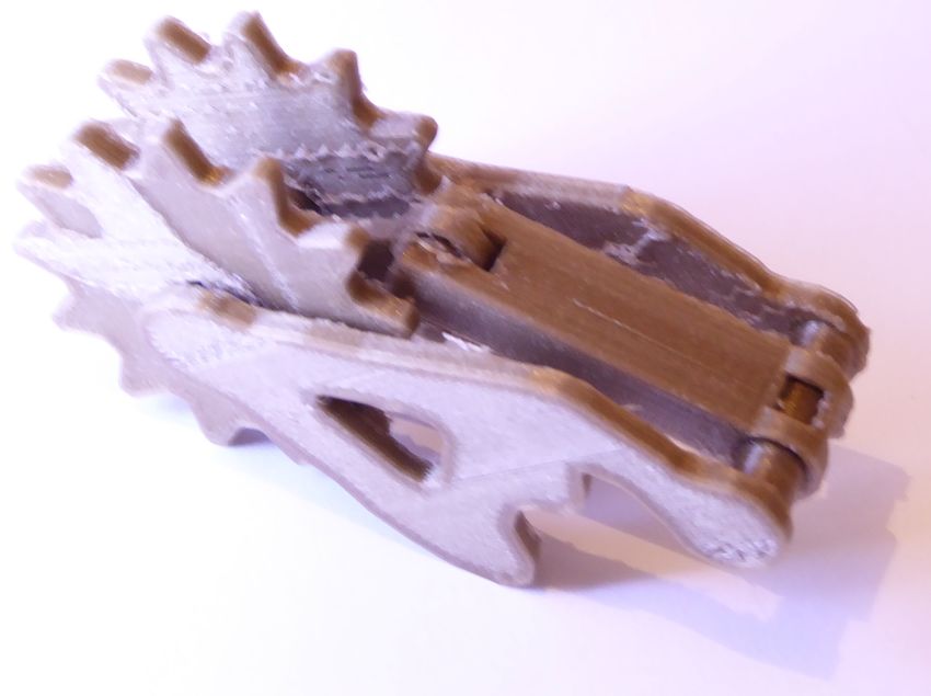
J. Hergel & S. Lefebvre / 3D Fabrication of 2D Mechanisms

                                                                                         a part may have holes, but has to form a single component.
                                                                                         The parts may be connected through hinges and fixed joints.
                           n6      n1
                                                                                         We denote the set of joints:
                            n2               n5
                                                                                         H = {(Pi , Pj )|Pi , Pj connected by an hinge or a fixed joint}

                                                                                            Our approach involves three steps: layout (Section 4),
                                        n3              n7

                                                  n4
                                                                                         geometry synthesis (Section 5) and chassis synthesis (Sec-
                                                                                         tion 6). These three steps are illustrated in Figure 3.
                                                                                              The layout step determines the relative positions of parts
                                                                                         and assigns them with a depth interval. We denote I(Pi ) =
Figure 3: Left: Input 2D mechanism. Middle: Graph used
                                                                                         [li , hi ] the interval assigned to part Pi , with li ≤ hi two in-
to construct the layout. Edge orientation indicates which
                                                                                         tegers. The inclusions between parts are determined by ori-
part include which other, while the red edges show which
                                                                                         enting edges in a graph capturing contact and collision con-
parts have to be layered. Right: Two views of the gener-
                                                                                         straints. The geometry synthesis step determines the exact
ated mechanism. The synthesized chassis appears in pink.
                                                                                         3D geometry of each part, using the layout and the motions
The crankshaft configuration automatically results from the
                                                                                         resulting from the simulated mechanism. The last step syn-
inclusion and layering constraints.
                                                                                         thesizes a chassis for the mechanism: a geometry for the
                                                                                         main body holding everything together.
the designers intent: e.g. folding or opening panels covering
certain areas. Thomaszewski et al. [TCG∗ 14] and Megaro et
                                                                                         4. Mechanical layout
al. [MTG∗ 14] propose to assist the user in creating elegant
linkage based animated figures. While the former focuses on                              Our approach produces mechanisms favoring inclusion be-
professional designers, the work of Megaro et al. targets ca-                            tween parts. This is used in particular to resolve cases where
sual users through an accessible, simple interface.                                      the parts overlap in the 2D specification without interacting.
                                                                                         The main advantage of this approach is to reduce mechani-
   These approaches focus on the automatic synthesis of the
                                                                                         cal jitter: the hinge axles are much stronger when supported
mechanism: the user does not directly model its inner work-
                                                                                         on both their extremities. Inclusion alone cannot work on
ings. While we fully agree on the importance of automatic
                                                                                         all mechanisms due to additional geometric constraints and
synthesis of mechanisms, our goal is to also promote the pos-
                                                                                         interactions between parts. For these cases our approach re-
sibility for casual users to directly design mechanisms. Con-
                                                                                         sorts to layering, but only locally.
trary to synthesis techniques, our approach never changes
the input mechanism and therefore cannot improve or cor-                                    The layout process starts by analyzing the simulated
rect it. We however impose no constraint on the parts and                                mechanism, tracking overlaps and interactions between parts
their interactions: we support gears, cranks and cams of any                             (Section 4.1). This information provides us with a set of
shapes as their functions arise from their 2D geometries and                             observations that are used to make hypotheses regarding
interactions. In contrast synthesis techniques often rely on a                           which parts can include which others (Section 4.3). Our al-
set of pre-determined mechanical parts – typically bars and                              gorithm greedily add inclusions, until contradictions are de-
gears – to make the problem tractable.                                                   tected (such as having both A ⊃ B and B ⊃ A). These con-
                                                                                         tradictions are transformed into layering rules. The final op-
   Several of the aforementioned techniques [CTN∗ 13,
                                                                                         timization assigns depth values to the intervals by solving a
CLM∗ 13, TCG∗ 14, MTG∗ 14] synthesize a 2D mechanism
                                                                                         constrained satisfaction problem (Section 4.4).
which is then turned into a fabricable 3D model. This is
solved by a layering approach: the potential collisions are
                                                                                         4.1. Analysis
identified and the parts are assigned different layers to avoid
collisions. This can be formulated as a constrained satisfac-                            Our approach starts by simulating the mechanism to con-
tion problem (CSP). This is a natural solution, but it tends                             struct the set of observations. It keeps track of overlaps –
to place parts side by side on a same axle, sometimes with                               parts that overlap without colliding – and interactions – parts
significant space in between, resulting in out-of-plane mo-                              that are allowed to be in contact during the simulation. This
tions and bending stresses on the axles (Section 1, Figure 2).                           is done by simulating the input 2D mechanism using the
In contrast, our technique favors inclusion of parts within                              Box2D library.
each others. Our system is able to locally switch to layering
                                                                                            We assume mechanisms to have a periodic motion, and
whenever inclusion cannot be used.
                                                                                         run the simulation until a prior configuration is encountered,
                                                                                         or a user selected maximum time is reached. The result is a
3. Overview
                                                                                         set of T time frames. We denote by Mit the position matrix
The input to our algorithm is a set of N parts P = {Pi |i =                              of part Pi at time t ∈ [0, T [, and denote by Mit Pi the polygon
0..N − 1}, each described by a 2D polygon. The polygon of                                of part Pi at time t.

 c 2015 The Author(s)
Computer Graphics Forum c 2015 The Eurographics Association and John Wiley & Sons Ltd.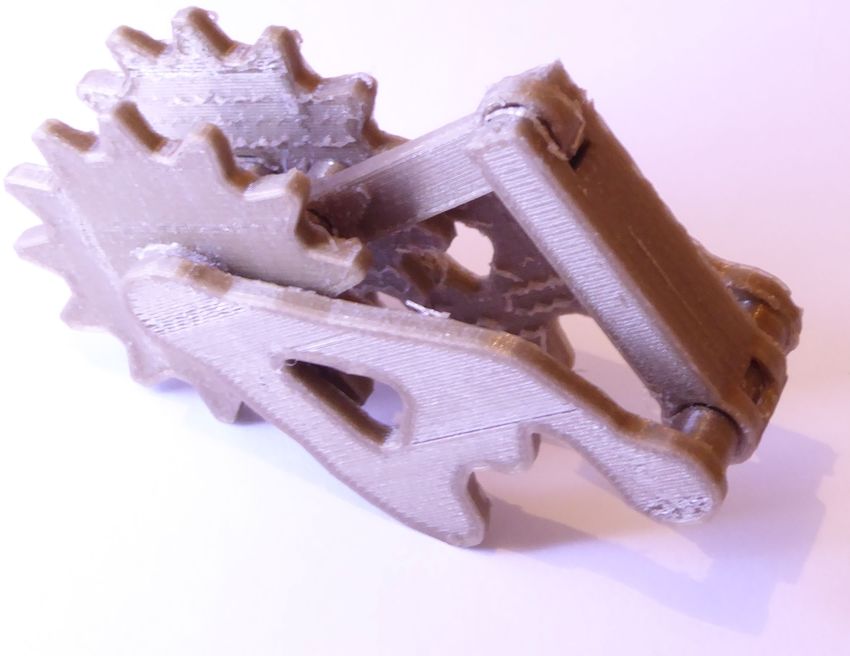
J. Hergel & S. Lefebvre / 3D Fabrication of 2D Mechanisms

We record all overlaps between parts in a set:                                4.2. Mechanical configurations

     O = {(Pi , Pj )|∃ t such that Pi , Pj overlap at time t}                 The mechanisms we generate can produce three types of me-
                                                                              chanical configurations between two parts A and B. Each
We keep track of all interactions between parts during simu-                  results in a rule regarding their intervals:
lation. We denote the set of interacting parts as:                            1. A includes B (denoted by A ⊃ B)
  C = {(Pi , Pj )|∃ t such that Pi , Pj are in contact at time t}                                             ⇒ I(A) ⊃ I(B)
Note that for any two parts Pi , Pj we have (Pi , Pj ) ∈ O ⇒                  2. A interacts with B
           / C and (Pi , Pj ) ∈ C ⇒ (Pi , Pj ) ∈
(Pi , Pj ) ∈                                   / O. We also have
                                                                                      ⇒ (I(A)\ ∪∀P⊂A I(P)) ∩ I(B)\ ∪∀Q⊂B I(Q) 6= ∅
H ⊂ O since all parts sharing a joint also overlap.
                                                                              3. A layered with B
   From these sets we define the mechanism graph as G =
(P, H ∪ O ∪ C). The set of edges is the union of the joint set                                              ⇒ I(A) ∩ I(B) = ∅
H, the overlap set and the contact set. Each edge in the graph                   These configurations are depicted in Figure 5. They are
is tagged to track which set it belongs to (edges in both H                   mutually exclusive: if A is layered with B they cannot inter-
and O are tagged as belonging to H).                                          act as they share no interval in depth. If A is layered with B,
                                                                              then B cannot be included within A (and vice-versa) as they
   Additional observations are made about the mechanism.
                                                                              also share no interval. If A includes B, then the volume of
The first are erasing cases. A part Pj is said to erase a part Pi
                                                                              B is carved out from A (see Figure 5 top-left) and therefore
if the temporal sweep of its polygon covers Pi entirely and
                                                                              they cannot interact.
they are not connected by a joint. More formally:
                                                                                 Whenever possible our algorithm favors inclusion over
Pj erases Pi if Pi \∪t∈[0,T [ ((Mit )−1 Mtj Pj ) = ∅ and (Pi , Pj ) ∈
                                                                    /H        the other two configurations.
In such cases, the part Pi cannot include the part Pj as it
would have to be split in two independent parts to fit Pj                     4.3. Generating inclusions
within its depth. If Pi , Pj are connected by a joint, then Pi                The goal of this step of the algorithm is to generate as
remains connected through the axle and is not erased by Pj .                  many inclusion configurations as possible. To this end, we
   The second are detachment cases. A part Pj is said to de-                  exploit the observations made during analysis and greedily
tach Pi , Pk (k 6= j) if the temporal sweep of Pj overlaps with               attempt to include parts into one another. Whenever inclu-
the joint between Pi , Pk . Note that the overlap test is consid-             sion cannot be used we fallback to layering. At this stage we
ering the diameter of the joint axle (5 mm in practice). If Pj                only determine relationships between the parts intervals (e.g.
detaches Pi , Pk then we request that Pj includes both Pi and                 I(A) ⊃ I(B)). The exact values of the depth intervals will be
Pk to avoid having Pj cross the axle between Pi , Pk .                        computed at the next stage (Section 4.4).
                                                                                 Inclusion relationships are determined by orienting the H
  These cases are illustrated Figure 4.
                                                                              and O edges of the mechanism graph G (Section 4.1). An
                                                                              edge (Pi → Pj ) implies that I(Pi ) ⊃ I(Pj ). The goal is to
                                                                              find an acyclic orientation: an inclusion cycle would pro-
                                                                              duce an unsolvable case of circular inclusion, e.g. I(Pi ) ⊃
                                                                              I(Pj ) ⊃ I(Pi ). When orienting the edges we take care not to
                                                                              contradict the interaction rules (recall that A includes B is in-
                                                                              compatible with A interacts with B, see Section 4.2). This is
                                                                              done by verifying that no inclusion path is formed between
                                                                              two parts A and B if they interact in the input mechanism.

Figure 4: Left: The bar A sweeps across the (fixed) bar B,
covering it entirely during the simulation. A is said to erase
B. In this case, B cannot possibly include A within its depth
or it would be disconnected in two independent parts. Right:
During simulation, the bar A sweeps across the hinge be-
tween B and C. A is said to detach B and C. In this case                      Figure 5: Two parts in the three possible configurations,
we request A to include B and C so that their axle is not cut                 as seen from above. Inclusion (top-left), interaction (bottom
by A. Note that these constraints will be combined and may                    left), layering (right). The configurations can be mixed, i.e. a
conflict, in which case layering will be locally performed.                   part can include others that are in a layering configuration.

                                                                                                                                          c 2015 The Author(s)
                                                                         Computer Graphics Forum c 2015 The Eurographics Association and John Wiley & Sons Ltd.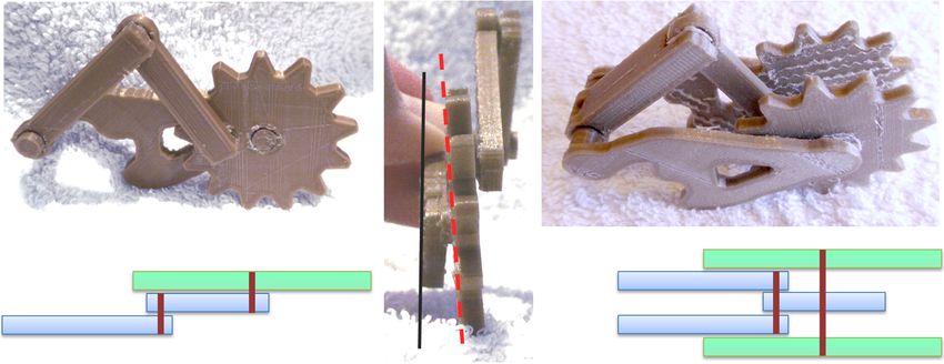
J. Hergel & S. Lefebvre / 3D Fabrication of 2D Mechanisms

  The orientation of some of the edges is constrained by the                             Chassis. The chassis appears as a part in the graph. To guar-
erasing and detachment cases:                                                            antee that it includes all other parts, we orient the chassis
                                                                                         edges prior to considering any other edge in the graph.
 Pj erases Pi                  ⇒      I(Pj ) ⊃ I(Pi )
 Pj detaches (Pi , Pk )        ⇒      I(Pj ) ⊃ I(Pi ) and I(Pj ) ⊃ I(Pk )                   Figure 2 illustrates a case where the chassis is involved in
                                                                                         a detachment constraint. In such cases, we request the de-
As a result of these constraints, contradictions may appear
                                                                                         taching primitive to be the most included. That is, Pj de-
during the orientation process, where both I(Pi ) ⊃ I(Pj )
                                                                                         taches (Pi ,C) implies I(Pj ) ⊂ I(Pi ) and I(Pj ) ⊂ I(C), where
and I(Pi ) ⊂ I(Pj ) are required. Such cases are resolved by
                                                                                         C is the chassis. The axle between C and Pi will exist around
switching to a layering configuration for Pi and Pj .
                                                                                         Pj – even though Pj cuts it, it will exist in two parts attaching
   We orient the edges of G considering edges in H first and                             C and Pi on both sides. E.g. in Figure 2 the main wheel axle
then edges in O. In each subset, we start by the edges with                              is cut by the inner arms. Nevertheless the wheel is properly
a constraint. This order is important: we prefer to avoid lay-                           connected on both sides to the chassis, and remains a single
ering on joints (set H) since this is the case where fragile                             part through the axle with the arm. This is possible as long
axles are generated. We therefore orient the edges in H first,                           as Pj does not erase Pi , in which case layering would auto-
so that contradictions are more likely to appear on the edges                            matically be used between Pj and Pi . Indeed a contradiction
of O which are later considered.                                                         would then appear when orienting the edge (Pi , Pj ).

   For each edge in sequence, we first determine which ori-                              Orientation cost heuristic. Whenever we can freely
entations are possible. This involves checking for an exist-                             choose the orientation of an edge, we apply the following
ing constraint, verifying whether an orientation violates any                            cost heuristic. In absence of constraints our goal is to avoid
interaction rule, and then checking whether an orientation                               thickening the parts too much. In other words, we want to
would produce an inclusion cycle. If two orientations are                                keep the size of the depth intervals |I(Pi )| small. The inter-
possible we use a heuristic to select the orientation of low-                            vals are optimized at the next step (Section 4.4) and there-
est cost (see below). If no orientation is possible, we have                             fore we do not know their exact size during graph orienta-
encountered a contradiction.                                                             tion. However, we can easily determine a lower bound. Con-
                                                                                         sider a path in the oriented graph from part Pi to part Pk :
Contradictions. We deal with contradictions by removing                                  Pi → ... → Pk and denote L the length of this path. Since we
the problematic edge from the graph and by adding a layer-                               have Pi ⊃ ... ⊃ Pk , it follows that |I(Pi )| ≥ L. We therefore
ing configuration rule between the parts: I(Pi ) ∩ I(Pj ) = ∅.                           seek to minimize the length of the longest path from every
This forces Pi and Pj to be in different depth intervals in-                             node. When orienting an edge (Pi , Pj ) we select the orienta-
stead of being included into one another. However, this in-                              tion minimizing L(Go , Pi ) + L(Go , Pj ) where L(Go , P) com-
troduces an additional requirement on the graph orientation:                             putes the longest path from P to any other node in the ori-
the parts Pi and Pj should not have any common descen-                                   ented graph Go (the graph with only the previously oriented
dant in the oriented graph. Let us assume such a descendant                              edges, and the edge being tested).
Pk exists. We would have I(Pi ) ⊃ I(Pk ) and I(Pj ) ⊃ I(Pk )
which gives (I(Pi ) ∩ I(Pj )) ⊃ I(Pk ). This directly contradicts                        4.4. Depth intervals
I(Pi ) ∩ I(Pj ) = ∅. To account for this, every time a contradic-
                                                                                         The previous step produces a number of rules relating the
tion is detected we add the additional constraint that Pi , Pj
                                                                                         depth intervals of the parts. The goal of this section is to
should not have a common descendant. The set of descen-
                                                                                         compute the depth values assigned to the lower and upper
dants is easily maintained during the graph orientation al-
                                                                                         bounds of each interval I(Pi ) = [li , hi ]. We assign integer
gorithm, and we reject any edge orientation that would vi-
                                                                                         depth values to the intervals, which are later mapped to phys-
olate such a requirement. When checking for common de-
                                                                                         ical thicknesses in the final object (see Section 5). Intervals
scendants we also follow interaction edges (edges in C) to
                                                                                         where li = hi correspond to parts having the minimal thick-
prevent the layered parts to include parts that have to inter-
                                                                                         ness (2 mm in practice).
act, i.e. Pu ⊂ Pi , Pv ⊂ Pj where Pv , Pu interact : this would
result in a similar contradiction.                                                          After the analysis we obtain three types of interval rules:
                                                                                         inclusion (e.g. I(Pi ) ⊃ I(Pj )), layering (e.g. I(Pi ) ∩ I(Pj ) =
   Resolving a contradiction by layering removes all detach-
                                                                                         ∅) and interactions.
ment constraints between Pi , Pj : as both parts will be placed
in non-intersecting depth intervals, they can no longer cross
                                                                                         Inclusion. Inclusions are captured by the oriented edges in
their respective axles.
                                                                                         G. They result in the following inequalities:
   Since the set of constraints is updated, and because some
                                                                                                      I(Pi ) ⊃ I(Pj ) ⇒ li < l j and hi > h j
earlier choices may violate the new constraints, we restart
the graph orientation every time a contradiction is resolved.                            Note the use of strict inequalities, which guarantees that the
When the process restarts edges are traversed the same order,                            including part (Pi ) has one layer on each side of the included
skipping the edges removed due to contradictions.                                        part (Pj ). This ensures that axles are supported on both sides.

 c 2015 The Author(s)
Computer Graphics Forum c 2015 The Eurographics Association and John Wiley & Sons Ltd.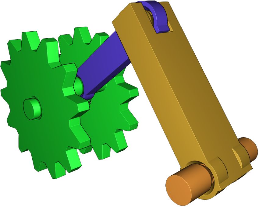
J. Hergel & S. Lefebvre / 3D Fabrication of 2D Mechanisms

Layering. Layering rules are produced when resolving con-
tradictions on edge orientations. We distinguish layering due
to the removal of an overlapping edge (∈ O) from the layer-
ing due to the removal of an hinge edge (∈ H).                            Figure 6: Left: Four bars seen from the top. Black segments
                                                                          indicate a fixed joint, while orange indicates a hinge joint.
On overlapping edges:                                                     C,D can rotate around A,B but will cut the fixed axle between
 Pi layered by overlap with Pj ⇒ li > h j + 1 or l j > hi + 1             A,B. This system cannot be resolved by assigning different
                                                                          layers to A,B,C,D. Right: The only solution is to change the
These inequalities guarantee that Pi , Pj will have a spacing             shape of the axle, making room for C,D.
of at least one between them, ensuring an including parent
piece will support their axles on both sides.
                                                                          5. Part geometry synthesis
On hinge edges:
                                                                          This step of the process takes as input the set of parts Pi , i =
  Pi layered by hinge with Pj ⇒ li = h j + 1 or l j = hi + 1              0...N and their corresponding depth intervals I(Pi ) = [li , hi ].
This constrains both parts to appear next to each others                  The output is the 3D geometry of each part.
through depth, ensuring that the axle between them is as                  In order to produce the 3D geometry we take into account
short as possible.                                                        the following:

Interactions. These rules are necessary to enforce that con-              • Parts have to be carved to allow for passage of other, in-
tacts exploited by the mechanisms (gears, racks) are prop-                  cluded parts.
erly captured by the 3D model. They result in the following               • Parts that come in contact have to be modified to take a
equalities:                                                                 spacing tolerance into account (0.4 mm in practice).
                                                                          • Parts that slide along others without being attached to the
    (Pi , Pj ) ∈ C ⇒ li = l j or li = h j or hi = l j or hi = h j           chassis have to be maintained at their selected depth.
This ensures that the parts will properly interact through                • The geometry of hinge joints has to be produced, enabling
their top or bottom layers. This rule is more restrictive than              the mechanism to print pre-assembled.
it could be, since in principle the parts interact as long as             The base shape of a part is formed by the linear extrusion
they share an interval where no included part exists (see Sec-            along the z axis (depth) of its 2D shape. We denote by Bi
tion 4.2). However, we found it sufficient in practice while              the base volume of part Pi . The position of the part in depth
reducing the combinatorial complexity for the CSP solver.                 is computed such that pieces allotted in consecutive layers
                                                                          are separated by a small space. For an interval [li , hi ], the
4.5. Solver                                                               extrusion takes places between zli = (t + s)li and zhi = (t +
                                                                          s)(hi + 1) − s where t is the minimal thickness (2 mm) and s
We directly translate these rules into an integer constraint
                                                                          the spacing tolerance between consecutive parts (0.4 mm).
problem that we solve using Minion [GJM06]. We restrict
the space of integer to [0, 2 · N], with N the number of parts.               The final shape Si is obtained from Bi by subtracting from
   Minion returns the solution minimizing the sum of part                 the initial volume the time sweep of the pieces included in
thicknesses, that is ∑N                                                   Pi , as well as the time sweep of the pieces in contact with
                       i=0 |I(Pi )|. As Minion performs an ex-
haustive search within the solution space, we configure it to             Pi . All subtracted pieces are dilated by the contact tolerance
return the best solution found after at most 90 seconds.                  spacing. The volume Si is precisely defined as:

   Once the intervals are determined for each part, we are                      Si = Bi \ ∪ j∈N (i) ∪t∈[0,T [ ((Mit )−1 Mtj B j ) ⊕ B0.4
                                                                                                                                     z

ready to generate the final geometry of the 3D parts.
                                                                          where N (i) = { j|(Pi , Pj ) ∈ O ∪ C}, ⊕ is the dilation oper-
                                                                                     z
                                                                          ator and B0.4 is a cylinder of axis z, of height and diameter
4.6. Discussion, failure cases                                            0.4 mm. We compute the shape by a combination of 2D oper-
At worse our algorithm eliminates all edges between the                   ations using the Clipper library [Joh10], and a few 3D CSG
parts in the graph and includes everything in the chassis. The            operations.
parts will then be layered within the chassis, which becomes
a crankshaft hosting the layered mechanism.                               Free assemblies. The mechanism might include parts, or
                                                                          sub–assemblies of parts that are not connected to the back-
   However, this does not guarantee success as some mecha-
                                                                          ground by any hinge: they are only sliding along other parts.
nisms cannot be layered. Such a case is shown Figure 6. The
                                                                          We call these free assemblies. They are detected as discon-
only solution involves modifying the shape of the fixed joint
                                                                          nected components in the graph with only H edges.
between the two bars. This is not considered by our system
nor, to the best of our knowledge, by any of the existing tech-              Free assemblies require special care: in 3D nothing pre-
niques. In such cases, the CSP solving for the intervals will             vents them from falling out of their assigned depth interval –
admit no solution.                                                        recall however that we assume that they are properly locked

                                                                                                                                      c 2015 The Author(s)
                                                                     Computer Graphics Forum c 2015 The Eurographics Association and John Wiley & Sons Ltd.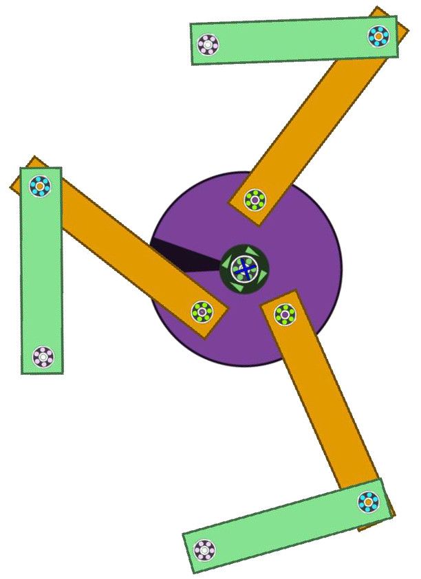
J. Hergel & S. Lefebvre / 3D Fabrication of 2D Mechanisms
This problem is elegantly answered by topology optimiza-
tion techniques [Ben89].
6.1. Background on topology optimization
We cast chassis synthesis as a case of 2D topology optimiza-
tion for minimizing the compliance energy [Ben89, Sig01].
The optimization domain is a grid of square elastic elements
where each element i, j takes a density ρi, j ∈ [ρmin , 1]. We
denote by ρ the vector of all element densities. Given a
choice of densities and a set of fixed elements where the
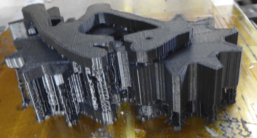
Figure 7: Left: The part in pink slides along the L-shaped structure is anchored, the finite element method can be used
part. Our approach generates fins around the sliding part to compute the planar deformation due to a set of forces
so that it is locked in depth inside surrounding parts. Mid- f = f1 , ..., fn located at the grid nodes (element corners). The
dle: Printed result, note how the gear is also carved by the displacement vector for all grid nodes u is obtained by solv-
fin. Right: Interlocking shape of the axles allowing for pre- ing K(ρ) · u = f where K(ρ) is the global stiffness matrix
assembled printing on filament based printers. assembled from the elements. The stiffness matrix of an el-
ement ρi, j is given by ρ3i, j Ke where Ke is the 8 × 8 stiffness
inside the 2D mechanism, see Section 1. We address this is- matrix of a square element in the target material.
sue by creating fins (protrusions) along the sliding parts, see
Figure 7. These fins are added to the base shapes Bi of the The compliance energy is defined as E(ρ) = f · u. Mini-
parts, and are thus subtracted from the other parts that are in mizing the compliance maximizes the rigidity of the system
contact (with a spacing tolerance). They physically constrain under the given forces. This energy is minimized by gradient
the parts to remain aligned in depth. descent under the constraint that ∑i, j ρi, j = A, where A is the
target area of the produced structure. Thanks to the cubic ex-
This approach in currently limited to the case of free as- ponent in the per-element stiffness, the system tends to use
semblies sliding against non-free assemblies: we do not sup- only 0 or 1 for ρi, j .
port several free assemblies sliding against each others.
6.2. Chassis optimization
Hinges. The geometry of the hinges is designed to allow
for pre-assembled printing (see Figure 7, right). We add the The chassis has to resist to the forces exerted by the mech-
hinges by CSG, carving the parts to let the axles through. anism at all times. We therefore record the forces at the
If the part is too narrow the axle geometry will introduce a joints attached to the background for the entire simulation.
local bulge to ensure the axle fits properly – in some cases This gives us a set of T force configurations, where T is
this can prevent the mechanism to function, e.g. if a surface the number of time frames. We optimize the chassis by
along which two parts interact is modified. We do not cur- maximizing the compliance over all time frames, that is
rently address this issue. E(ρ) = ∑t∈T ft · ut where K(ρ)ut = ft . This is made efficient
by pre-factoring the stiffness matrix K and then solving for
After this stage the mechanism is almost ready to print, ut for all time frames.
but still lacks a chassis.
We select a resolution of 2 mm per pixel, a Poisson ra-
6. Chassis synthesis tio of 0.35 and an elastic modulus of 2.3 GPa (ABS plastic
material). The target area A is set to 10% and then reduced
When designing mechanisms in 2D the user attaches primi-
until the structure is disconnected. We select the last value
tives to the background ’wall’. When creating the 3D coun-
generating a fully connected structure. The final outline of
terpart of the mechanism we have to synthesize a chassis
the shape is extracted by smoothing out the result with a box
acting as the background. We produce a 2D geometry that is
filter of size 3 × 3 and then contouring the isovalue 0.25. The
used to sandwich the 3D mechanism in between two walls,
process is summarized Figure 8.
as illustrated Figure 2. Alternatively the chassis could be ex-
truded to the full mechanism depth and carved like any other
7. Results
part, see Section 5. This is unnecessary unless the chassis
is a crankshaft, so to reduce material use and print time we We modeled all our results using Algodoo, with the only con-
prefer the sandwiching approach in practice. straint that the mechanisms have to function properly in 2D
and be in a valid position (interacting parts such as gears
The trade-offs in synthesizing the chassis are that we want
should not overlap). By default the models are rescaled so
it to be strong enough to support the efforts generated by the
that their bounding box fits a 150 × 150 mm square.
mechanism, but at the same time we would like to keep it
small to reduce material use, print time and for aesthetics All the 3D mechanisms are generated automatically from
reasons (a thick chassis would hide the mechanism entirely). the scenes created in Algodoo, without any user intervention.
c 2015 The Author(s)
Computer Graphics Forum c 2015 The Eurographics Association and John Wiley & Sons Ltd.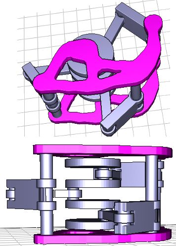
J. Hergel & S. Lefebvre / 3D Fabrication of 2D Mechanisms

                                                                        7.1. 3D printing
                                                                        We print all our objects on inexpensive filament printers in
                                                                        ABS and PLA plastic: a Replicator 1 from Makerbot, and
                                                                        Ultimakers 1 and 2 from Ultimaker.
                                                                           All objects are printed in one piece, using support. We
                                                                        experimented both with dissoluble plastic and a weak filling
Figure 8: Chassis synthesis by topology optimization. Left:
                                                                        pattern for support. We had better results using a weak infill
four forces resulting from hinges at a given time frame (pink)
                                                                        pattern. See Figure 9 for an example of a print before and
and attachment point (gray). Middle: Optimized densities
                                                                        after cleanup.
for these forces. Right: Final shape after smoothing and con-
tour extraction.                                                           Our mechanisms exploit the fact that 3D printers can pro-
                                                                        duce pre-assembled articulated objects, so that we do not
                                                                        have to consider the assembly stage. However, this is not
                                                                        necessarily the best option of filament printers. In particular
                                                                        after printing some force has to be exerted to free the mech-
                                                                        anism from inaccessible support. One issue we encountered
                                                                        is breaking of the plastic axles when applying force. The EG
Figure 9: Left: Model after printing, with weak infill sup-
                                                                        flag design, for instance, broke when we freed the sliding
port. Right: Cleaned model. The gears have rotated, note
                                                                        part and we had to use screws to reassemble it manually. An
the small leftover from the infill pattern on top of the gears.
                                                                        interesting direction of future work is to split the mechanism
                                                                        into pieces that are easy to assemble [LBRM12, VGB∗ 14].
    Figure 10 shows a number of printed results. From top-left
to bottom right: the Gear Puppet model is made of six gears
                                                                        8. Conclusion
with custom shapes. The small brown box indicates the base
for the chassis. The EG flag model is a case of sliding part.           A major advantage of our algorithm is that it avoids search-
The model has automatically generated fins along the slid-              ing for explicit kinematic configurations. The algorithm has
ing part that are carved from both the L-shaped part and the            no notion of what a gear or rack is, their function is solely
gear. This model broke during clean up and we used screws               given by their shape and the simulation. All the mechanical
to repair it (see also Section 7.1). The Scissor model is a case        configurations, for instance the crankshafts, automatically
where no chassis is needed. It is actioned by a hidden mech-            emerge from the set of constraints. Inclusion produces parts
anism which is ignored by our system after simulation. This             holding axles on both sides, which is generally less sensitive
shows how our algorithm alternates inclusions as a result of            to mechanical jitter and stress.
the edge orientation cost heuristic. The Wheel model illus-
                                                                           The are limitations in our current implementation. First,
trates how part geometry is automatically created to allow
                                                                        joints can only be defined between two parts. Second, we
for passage of included objects. The green box at the bot-
                                                                        do not detect the case where a part is erased (Section 4.1)
tom of the design indicates the base of the chassis. The Gear
                                                                        by the cumulative effect of two or more other parts. Both of
Train model is case of cyclic interaction between gears, cre-
                                                                        these cases lead to a large number of possibilities for includ-
ating a layering between the two central gears. The Three
                                                                        ing parts into one another. One possibility is to fallback to
Leg model is a case that results automatically in a crankshaft.
                                                                        layering in such situations.
It is also shown Figure 3.
                                                                           There can be aesthetics considerations to using inclusion
  The complexity of our printed results is limited by the ca-
                                                                        or layering, and to which part should include which other.
pability of our printers. We show in Figure 11 and Figure 12
                                                                        User control can be achieved by directly editing the con-
outputs of our algorithm on more complex designs. Our sys-
                                                                        straint graph, allowing to explore several possibilities.
tem is capable of keeping the overall design thickness small,
while exploiting inclusions wherever possible.                             Our approach makes designing mechanisms less difficult
                                                                        by automatically dealing with many of the intricate techni-
Performance. Most results are computed in a few seconds.                cal details required to generate a valid 3D geometry for a
For instance, for the small model Figure 1 graph orientation            pre-assembled mechanism. We hope it will help hobbyists,
takes 154 ms, Minion returns the CSP solution in 7 ms. For              teachers, educators and 3D printing enthusiasts to fully ex-
the larger model Figure 12 graph orientation takes 489 ms,              ploit the potential of their printers.
Minion returns the CSP solution after 90 seconds as it ex-
plores for the best possible solution until the timeout. Run-           Acknowledgments This work was funded by ERC Shape-
ning for longer does not return a better solution, but Minion           Forge (StG-2012-307877). We thank the Région Lorraine
has to finish exploring the space to guarantee the optimal is           for funding some of our equipment, as well as the anony-
found. Chassis optimization takes 2.34 seconds.                         mous reviewers for their help with improving the paper.

                                                                                                                                    c 2015 The Author(s)
                                                                   Computer Graphics Forum c 2015 The Eurographics Association and John Wiley & Sons Ltd.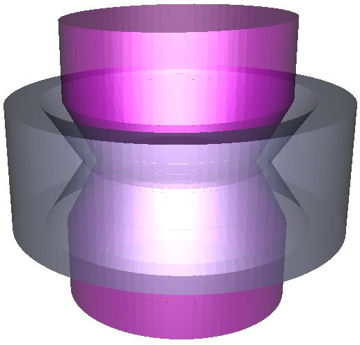
J. Hergel & S. Lefebvre / 3D Fabrication of 2D Mechanisms

Figure 10: A variety of results automatically generated from the input 2D design. Please also refer to the accompanying video
clips to see them in motion. All these results are 3D printed on filament printers.

References                                                                                 G RINSPUN E., C OROS S., G ROSS M.: Chacra: An interac-
                                                                                           tive design system for rapid character crafting. In Symposium
[BBJP12] BÄCHER M., B ICKEL B., JAMES D. L., P FISTER H.:
                                                                                           on Computer Animation (SCA) (2014), pp. 123–130. 3
  Fabricating articulated characters from skinned meshes. ACM
  Transactions on Graphics 31, 4 (2012), 47:1–47:9. 2                                    [PWLSH13] P RÉVOST R., W HITING E., L EFEBVRE S.,
                                                                                           S ORKINE -H ORNUNG O.: Make It Stand: Balancing shapes for
[Ben89] B ENDSØE M. P.: Optimal shape design as a material
                                                                                           3D fabrication. ACM Transactions on Graphics 32, 4 (2013),
  distribution problem. Structural Optimization 1 (1989), 192–202.
                                                                                           81:1–81:10. 2
  7
                                                                                         [Sig01] S IGMUND O.: A 99 line topology optimization code writ-
[BWBSH14] BÄCHER M., W HITING E., B ICKEL B., S ORKINE -
                                                                                            ten in matlab. Structural and Multidisciplinary Optimization 21,
  H ORNUNG O.: Spin-it: Optimizing moment of inertia for
                                                                                            2 (2001), 120–127. 7
  spinnable objects. ACM Transactions on Graphics 33, 4 (2014),
  96:1–96:10. 2                                                                          [STC∗ 13] S KOURAS M., T HOMASZEWSKI B., C OROS S.,
[CCA∗ 12] C ALÌ J., C ALIAN D. A., A MATI C., K LEINBERGER                                 B ICKEL B., G ROSS M.: Computational design of actuated
  R., S TEED A., K AUTZ J., W EYRICH T.: 3d-printing of non-                               deformable characters. ACM Transactions on Graphics 32, 4
  assembly, articulated models. ACM Transactions on Graphics                               (2013), 82:1–82:10. 2
  31, 6 (2012), 130:1–130:8. 2                                                           [SVB∗ 12] S TAVA O., VANEK J., B ENES B., C ARR N. A.,
[CLM∗ 13]   C EYLAN D., L I W., M ITRA N. J., AGRAWALA M.,                                 M ECH R.: Stress relief: improving structural strength of 3d print-
   PAULY M.: Designing and fabricating mechanical automata from                            able objects. ACM Transactions on Graphics 31, 4 (2012), 48:1–
   mocap sequences. ACM Transactions on Graphics 32, 6 (2013),                             48:11. 2
   186:1–186:11. 1, 2, 3                                                                 [TCG∗ 14] T HOMASZEWSKI B., C OROS S., G AUGE D.,
[CTN∗ 13]    C OROS S., T HOMASZEWSKI B., N ORIS G., S UEDA                                M EGARO V., G RINSPUN E., G ROSS M.: Computational design
   S., F ORBERG M., S UMNER R. W., M ATUSIK W., B ICKEL B.:                                of linkage-based characters. ACM Transactions on Graphics 33,
   Computational design of mechanical characters. ACM Transac-                             4 (2014), 64:1–64:9. 1, 3
   tions on Graphics 32, 4 (2013), 83:1–83:12. 1, 2, 3                                   [VGB∗ 14] VANEK J., G ALICIA J. A. G., B ENES B., MÄ Ż CH
[GJM06] G ENT I. P., J EFFERSON C., M IGUEL I.: Minion: A                                  R., C ARR N., S TAVA O., M ILLER G. S.: Packmerger: A 3d
  fast, scalable, constraint solver. In Proceedings of ECAI 2006                           print volume optimizer. Computer Graphics Forum 33, 6 (2014),
  (2006), pp. 98–102. 6                                                                    322–332. 8
[Joh10] J OHNSON A.: Clipper - an open source freeware library                           [ZXS∗ 12] Z HU L., X U W., S NYDER J., L IU Y., WANG G., G UO
   for clipping and offsetting lines and polygons, 2010. 6                                 B.: Motion-guided mechanical toy modeling. ACM Transactions
                                                                                           on Graphics 31, 6 (2012), 127:1–127:10. 1, 2
[Koo14] Creating works-like prototypes of mechanical objects.
  ACM Transactions on Graphics 33 (2014), 217:1–217:9. 1, 2
[LBRM12] L UO L., BARAN I., RUSINKIEWICZ S., M ATUSIK
  W.: Chopper: Partitioning models into 3D-printable parts. ACM
  Transactions on Graphics 31, 6 (2012), 129:1–129:9. 8
[MTG∗ 14]       M EGARO V., T HOMASZEWSKI B., G AUGE D.,

 c 2015 The Author(s)
Computer Graphics Forum c 2015 The Eurographics Association and John Wiley & Sons Ltd.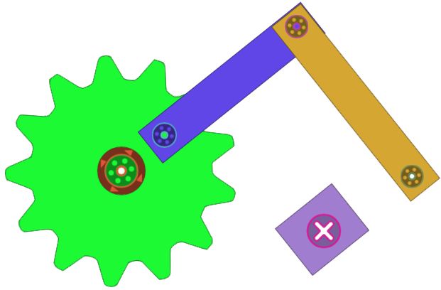
J. Hergel & S. Lefebvre / 3D Fabrication of 2D Mechanisms

                       n0        n12

 n1         n10                        n6                    n4

      n11   n14             n2         n7         n5              n8

                  n3                         n9

Figure 11: Eagle model. The mechanism shown in transparency (bottom) is generated from the design (top). The mechanism
graph (top left) shows inclusions and contact edges (bold blue). No contradictions were encountered: there is no layering. Note
the double gears including the bars, as well as the space carved for the inner bars in the bars actioning the wings.

                                                                   n0                   n9            n1       n24

                                                       n14                 n17     n5        n21      n16                     n8           n7

                                            n2                    n19        n10                     n22      n15       n4         n20          n13

                                                       n6                                                     n18                        n3           n11

                                                       n12

Figure 12: Frogger model. The mechanism shown in transparency (top right) is generated from the design (top left). This model
contains two crankshafts for steering the arms and legs. These were created by layering constraints (red bold edges in the
graph). Inclusions are used in most places. Note the lightweight synthesized chassis. One of the large wheel is doubled to avoid
the bottom bar of the neighboring crankshaft which overlaps during motion (edge between n15 and n16 in the graph).

                                                                                                                                                                    c 2015 The Author(s)
                                                                                                   Computer Graphics Forum c 2015 The Eurographics Association and John Wiley & Sons Ltd.
You can also read