A Potential Vorticity Theory for the Formation of Elongate Channels in River Deltas and Lakes
←
→
Page content transcription
If your browser does not render page correctly, please read the page content below
University of Pennsylvania
                                                                                               ScholarlyCommons
Departmental Papers (EES)                                                     Department of Earth and Environmental Science

12-2010

A Potential Vorticity Theory for the Formation of
Elongate Channels in River Deltas and Lakes
Federico Falcini

Douglas J. Jerolmack
University of Pennsylvania, sediment@sas.upenn.edu

Follow this and additional works at: http://repository.upenn.edu/ees_papers
   Part of the Environmental Sciences Commons, Geomorphology Commons, and the
Sedimentology Commons

Recommended Citation
Falcini, F., & Jerolmack, D. J. (2010). A Potential Vorticity Theory for the Formation of Elongate Channels in River Deltas and Lakes.
Journal of Geophysical Research: Earth Surface, 115 (F4), F04038-. http://dx.doi.org/10.1029/2010JF001802

This paper is posted at ScholarlyCommons. http://repository.upenn.edu/ees_papers/76
For more information, please contact libraryrepository@pobox.upenn.edu.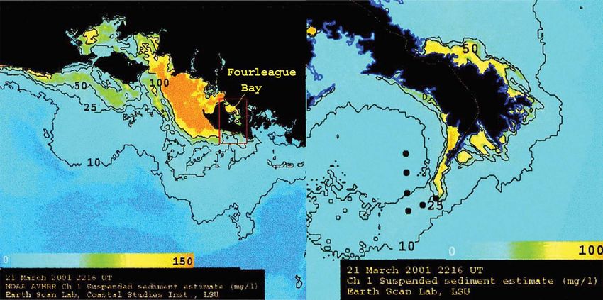
A Potential Vorticity Theory for the Formation of Elongate Channels in
River Deltas and Lakes
Abstract
Rivers empty into oceans and lakes as turbulent sediment-laden jets, which can be characterized by a Gaussian
horizontal velocity profile that spreads and decays downstream because of shearing and lateral mixing at the
jet margins. Recent experiments demonstrate that this velocity field controls river-mouth sedimentation
patterns. In nature, diffuse jets are associated with mouth bar deposition forming bifurcating distributary
networks, while focused jets are associated with levee deposition and the growth of elongate channels that do
not bifurcate. River outflows from elongate channels are similar in structure to cold filaments observed in
ocean currents, where high potential vorticity helps to preserve coherent structure over large distances.
Motivated by these observations, we propose a hydrodynamic theory that seeks to predict the conditions
under which elongate channels form. Our approach models jet velocity patterns using the flow vorticity. Both
shearing and lateral spreading are directly related to the vertical component of vorticity. We introduce a new
kind of potential vorticity that incorporates sediment concentration and thus allows study of jet
sedimentation patterns. The potential vorticity equation reduces the number of fluid momentum equations to
one without losing generality. This results in a compact analytical solution capable of describing the
streamwise evolution of the potential vorticity of a sediment-laden jet from initial conditions at the river
mouth. Our theory predicts that high potential vorticity is a necessary condition for focused levee deposition
and the creation of elongate channels. Comparison to numerical, laboratory, and field studies indicates that
potential vorticity is a primary control on channel morphology. Our results may be useful for designing river
delta restoration schemes such as the proposed Mississippi Delta diversion.

Keywords
river channel dynamics, river jets, sediment transport

Disciplines
Earth Sciences | Environmental Sciences | Geomorphology | Physical Sciences and Mathematics |
Sedimentology

                             This journal article is available at ScholarlyCommons: http://repository.upenn.edu/ees_papers/76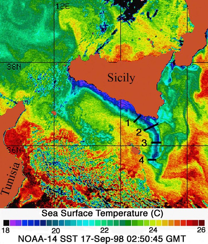
JOURNAL OF GEOPHYSICAL RESEARCH, VOL. 115, F04038, doi:10.1029/2010JF001802, 2010

A potential vorticity theory for the formation of elongate channels
in river deltas and lakes
Federico Falcini1 and Douglas J. Jerolmack1
Received 19 June 2010; revised 5 October 2010; accepted 14 October 2010; published 21 December 2010.
[1] Rivers empty into oceans and lakes as turbulent sediment‐laden jets, which can be
characterized by a Gaussian horizontal velocity profile that spreads and decays
downstream because of shearing and lateral mixing at the jet margins. Recent experiments
demonstrate that this velocity field controls river‐mouth sedimentation patterns. In nature,
diffuse jets are associated with mouth bar deposition forming bifurcating distributary
networks, while focused jets are associated with levee deposition and the growth of
elongate channels that do not bifurcate. River outflows from elongate channels are similar
in structure to cold filaments observed in ocean currents, where high potential vorticity
helps to preserve coherent structure over large distances. Motivated by these observations,
we propose a hydrodynamic theory that seeks to predict the conditions under which
elongate channels form. Our approach models jet velocity patterns using the flow vorticity.
Both shearing and lateral spreading are directly related to the vertical component of
vorticity. We introduce a new kind of potential vorticity that incorporates sediment
concentration and thus allows study of jet sedimentation patterns. The potential vorticity
equation reduces the number of fluid momentum equations to one without losing
generality. This results in a compact analytical solution capable of describing the
streamwise evolution of the potential vorticity of a sediment‐laden jet from initial
conditions at the river mouth. Our theory predicts that high potential vorticity is a
necessary condition for focused levee deposition and the creation of elongate channels.
Comparison to numerical, laboratory, and field studies indicates that potential vorticity is a
primary control on channel morphology. Our results may be useful for designing river
delta restoration schemes such as the proposed Mississippi Delta diversion.
Citation: Falcini, F., and D. J. Jerolmack (2010), A potential vorticity theory for the formation of elongate channels in river
deltas and lakes, J. Geophys. Res., 115, F04038, doi:10.1029/2010JF001802.

1. Introduction                                                         appears to occur by two simultaneous processes [Edmonds
                                                                        and Slingerland, 2007]: (1) deposition at jet margins leads
  [2] Sediment‐charged rivers discharging into oceans and
                                                                        to levee progradation and channel elongation while (2)
lakes often generate spectacular sediment plumes (Figure 1).
                                                                        deposition and vertical aggradation of a mouth bar in the jet
If the turbulent jet is not strongly disrupted by waves or
                                                                        centerline enhances flow divergence leading to bifurcation.
tides, focused sedimentation at its margins may confine flow
                                                                        The repetitive branching network that results from these
such that the river mouth progrades basinward [Wright,
                                                                        processes is the most common channel pattern seen on the
1977; Edmonds and Slingerland, 2007]. A good example
                                                                        shorelines of fluvially dominated deltas [Edmonds and
is the Mississippi River Delta, which shows that such pro-              Slingerland, 2007; Jerolmack and Swenson, 2007].
grading channels may take a variety of forms even under
                                                                          [3] A much less common morphology is the famous Ba-
similar environmental conditions (Figure 2). A man‐made
                                                                        lize lobe to the east on the Mississippi Delta, generally
diversion from the Atchafalaya branch of the Mississippi                referred to as the “birdsfoot” (Figure 2). Its morphology
has resulted in the rapid growth of the Wax Lake Delta
                                                                        indicates that channels somehow prograde great distances
(Figure 2), which now serves as an important prototype for
                                                                        without bifurcating [Kim et al., 2009b]. This is particularly
planned restoration schemes in the vicinity of New Orleans
                                                                        evident in the Southwest Pass channel (Figure 2) where,
[Parker and Sequeiros, 2006; Kim et al., 2009a; Edmonds
                                                                        despite dimensions and water discharges comparable to the
and Slingerland, 2007, 2010]. Wax Lake channel growth
                                                                        Wax Lake feeder channel, no bifurcation occurs. Although
                                                                        the modern channel has significant human influence, his-
   1
     Department of Earth and Environmental Science, University of
                                                                        torical and geologic records indicate that the birdsfoot
Pennsylvania, Philadelphia, Pennsylvania, USA.                          morphology was well established before large‐scale human
                                                                        interference [Fisk et al., 1954; Kim et al., 2009a]. Recent
Copyright 2010 by the American Geophysical Union.                       numerical simulations that include cohesive sediment re-
0148‐0227/10/2010JF001802

                                                                 F04038                                                           1 of 18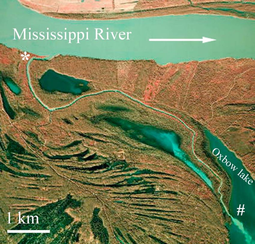
F04038              FALCINI AND JEROLMACK: FORMATION OF ELONGATE CHANNELS THEORY                                    F04038

         Figure 1. Different examples of jet plumes. (a) Experimental jet meander highlighted by fluorescent dye
         [from Rowland et al., 2009a]. (b) Aerial photograph of a tie channel outlet discharging into an oxbow
         lake connected to the lower Mississippi River near Baton Rouge, LA, USA [from Rowland et al., 2009a].
         (c) Sediment laden plumes in northern Gulf of Mexico from the Southwest Pass of the Mississippi
         birdsfoot (credit: NASA Earth Observatory).

         Figure 2. The lower Mississippi Delta and Louisiana coast, with the details of (a) Wax Lake Delta of the
         Atchafalaya River and (b) Southwest Pass of the Mississippi birdsfoot. Google Earth imagery ©Google
         Inc. Used with permission.

                                                         2 of 18
F04038 FALCINI AND JEROLMACK: FORMATION OF ELONGATE CHANNELS THEORY F04038
seems likely that cohesive sediments enhance this process
[Edmonds and Slingerland, 2010].
[5] We hypothesize that elongate (nonbifurcating) chan-
nels form where levee growth is rapid compared to within‐
channel or mouth‐bar depositions. Accordingly, in this
paper we seek to determine the hydrodynamic and sediment
transport conditions that lead to enhanced deposition at the
margins of the river effluent jet. Since detailed measure-
ments of flow and sediment transport at river mouths are
limited, in this paper we will employ satellite observations
of sea surface temperature and ocean color to examine the
hydrodynamics and sediment concentration of river out-
flows. We observe a qualitative similarity between elongate
channel jets and cold oceanic filaments [Bignami et al.,
2008], which are shallow veins of wind‐sheared water
having high potential vorticity and low lateral spreading
(Figure 4). This similarity provides the basis for a new
modeling approach, in which we adapt geophysical fluid
dynamics theory from oceanography to describe river mouth
jets. Recent tank experiments of river‐mouth levee deposi-
tion by Rowland [2007] and Rowland et al. [2010] provide
the main empirical motivation and constraints for our model.
Figure 3. Aerial photograph of one of the tie channels [6] Our approach is based on the premise that sediment‐
studied by Rowland [2007], near Baton Rouge, LA, USA laden river flows form a turbulent jet that expands and de-
(color infrared orthophoto, SW quadrant of Angola quad- celerates at rates that depend on initial hydrodynamic condi-
rangle, LA, 2004 U.S. Geological Survey Digital Ortho tions [Peckham, 2008, and references therein] and frictional
Quarter Quadrangles (DOQQs) source: http://atlas.lsu.edu/). effects. Friction and lateral mixing processes extract the along‐
Asterisk and number sign represent the channel junction
with the Mississippi River and the channel terminus at the
Raccourci Old River oxbow lake, respectively. Arrow
represents the Mississippi River flow direction.
produced the general birdsfoot shape [Edmonds and
Slingerland, 2010], but at present we still lack a quantita-
tive understanding of the conditions that give rise to bifur-
cating versus elongate channels. This hinders our ability to
predict, for example, land‐building patterns that would
result from restoration activities involving diversions on the
Mississippi and other deltas [Parker and Sequeiros, 2006;
Kim et al., 2009a].
[4] One common type of elongate channel seen in nature is
tie channels, secondary channels that connect rivers to
floodplain lakes [Rowland, 2007]. These remarkable features
can prograde indefinitely without bifurcation (Figures 1 and
3) and, taking the length of channel (L) by its width (B) as a
measure of elongation, they can reach L/B ∼ 80 (Figure 3).
Despite their diminutive size, tie channels bear a striking
similarity to distributaries on the Balize lobe and in particular
with the Southwest Pass which shows the same elongation
ratio (Figure 2). Tie channels appear to us to be an end‐
member of the birdsfoot morphology, prompting us to seek
similarity in the hydrodynamic and sediment transporting
conditions between these systems. Recent field and experi-
mental studies demonstrate that sediment transport in tie
channels is almost entirely in suspension, resulting in rapid Figure 4. NOAA/AVHRR sea surface temperature (SST)
levee growth and progradation [Rowland et al., 2009b]. It image (NOAA 14 satellite) for 17 September 1998 of SE Si-
seems reasonable to suppose that suspended sediment and cily (Italy) shoreline, showing a cold filament entering the
consequent levee growth at the river mouth is a necessary Ionian Sea. Numbers show the cross‐sectional measure-
condition for elongate channels. Experiments demonstrate ments of temperature contrasts between the core of the fila-
that cohesion is not necessary for subaqueous levee depo- ment and the surrounding water: (1) 3.485°C, (2) 3.395°C,
sition [Rowland, 2007; Rowland et al., 2009a], however it (3) 2.988°C, and (4) 2.20°C (courtesy of E. Salusti, 2009).
3 of 18F04038 FALCINI AND JEROLMACK: FORMATION OF ELONGATE CHANNELS THEORY F04038
Figure 5. Schematic representation for spreading, diffusion, and deceleration of a typical confined wall
jet. U0 is the main flow velocity at the river mouth. Shaded areas indicate the Gaussian shape of the hor-
izontal velocity profile, where the straight arrows represent the jet centerline velocity Uc. At the bottom,
the Zone of Flow Establishment (ZOFE) and the Zone of Established Flow (ZOEF) are shown; within
ZOFE Uc = const whereas within the ZOEF Uc = Uc (x) ≡ U0 (x/B)−g , where g is an experimental decay
parameter. The spreading angle is related to the coefficient q (see text). Bent arrows represent the lateral
entrainment/disentrainment with the ambient basin water and the fully turbulent regime experimentally
recognized in the ZOEF [Peckham, 2008; Rowland et al., 2009a].
flow mean kinetic energy, causing sediment deposition research has focused on the hydrodynamics of river outflows
[Wright, 1977; Edmonds and Slingerland, 2007; Peckham, [e.g., Bates, 1953; Abramovich, 1963; Rajaratnam, 1976;
2008]. The turbulent jet can be characterized in two di- Wright, 1977; Wang, 1984; Syvitski et al., 1998; Peckham,
mensions as a horizontal Gaussian velocity profile that 2008, and references therein]. Wright [1977] was the first
flattens and widens downstream due to shearing and lateral to directly relate different river mouth sedimentation patterns
mixing at jet margins [Albertson et al., 1950; Abramovich, seen on deltas to fundamental hydrodynamic controls
1963; Schlichting, 1968]. Following Pedlosky [1987], we (Figure 5). Beginning with knowledge of classical jet theory
derive the vorticity equation and characterize the hydrody- [Bates, 1953; Abramovich, 1963], he qualitatively assessed
namic pattern of a planar jet in terms of vorticity. We then the relative importance of frictional, inertial and buoyancy
introduce a new kind of potential vorticity (PV hereafter) effects for controlling delta morphology. In particular,
that incorporates sediment concentration. By means of the Wright [1977] introduced “inertia‐dominated effluents,”
Ertel PV theorem [Ertel, 1942; Pedlosky, 1987], we derive a supercritical jets characterized by a Gaussian lateral velocity
new equation for describing sedimentation patterns at the distribution, a high outflow velocity, a constant low
river mouth. The resultant PV model appears to explain key spreading angle and weak streamwise velocity decay. These
aspects of levee deposition and channel morphology, and is hydrodynamic conditions were thought to occur for deep
in reasonable agreement with experimental results [Rowland, channel outlets having little bed load transport. He proposed
2007; Rowland et al., 2009a]. Our theory predicts that high that the result of this flow configuration is a prograding,
PV is a necessary condition for the creation of elongate narrow lunate bar deposited in front of the channel mouth.
channels such as the Mississippi birdsfoot. Synthesis of “Friction‐dominated effluents,” characterized by a more
recently published field, laboratory and numerical studies moderate outflow jet velocity and rapid lateral expansion and
confirms that PV is an important control on channel mor- deceleration, were thought to give rise to rapid deposition of
phology. We conclude with suggestions for how the PV a mouth bar in the channel centerline resulting in bifurcation.
model could be used for designing water and sediment di- Wright [1977] suggested this kind of jet was associated with
versions to construct new delta lobes in threatened coastal shallow channel outlets having high bed load. To provide an
areas [e.g., Kim et al., 2009a]. explanation for elongated channels Wright [1977] introduced
“buoyant effluents,” critical flows (Froude number ∼1)
characterized by strong stratification resulting from the
2. Background in River Jet Dynamics salinity contrast between river outflows and the ocean, and
[7] Because river mouth sedimentation patterns are closely by an intermediate flow velocity. He proposed that such
related to the characteristics of turbulent jet spreading, much buoyancy flows generate a secondary circulation able to
4 of 18F04038 FALCINI AND JEROLMACK: FORMATION OF ELONGATE CHANNELS THEORY F04038
carry sediments from the centerline of the jet to the bound- to the initial width and depth of the parent channel, and also
aries. The idea of buoyancy effluents as an explanation for the initial velocity distribution and sediment grain size of the
elongated channels would appear to be refuted by the for- river jet at the channel mouth. Their results compare
mation of such channels in freshwater lakes; nonetheless, favorably to field observations of branching river deltas, but
Wright’s ideas provided the framework for subsequent simulations did not produce elongated channels. In a more
quantitative work. recent study [Edmonds and Slingerland, 2010], these au-
[8] A significant advance in understanding river mouth thors added cohesive sediments to the Delft3D model and
sedimentation was made by Edmonds and Slingerland were able to simulate elongate channels, showing how
[2007], who used the Delft3D coupled hydrodynamic‐ variations in cohesion alone may force transition from a
morphodynamic model to simulate the processes of mouth‐ branching to elongate morphology.
bar formation and levee growth resulting from an expanding [ 11 ] Recent laboratory tank experiments by Rowland
sediment‐laden jet. The three‐dimensional conservation of [2007] and Rowland et al. [2009a] provide empirical con-
momentum equations for unsteady, incompressible, turbu- straints for flow and sediment transporting conditions
lent flow introduced by Edmonds and Slingerland [2007], associated with the formation of elongated channels. Their
can be written in their general form as experiments were designed to mimic conditions of tie
channels (Figures 1 and 3), which are narrow, deep channels
@~
u 1 ~
F transporting fully suspended sediment that is debouched as a
þ ð~
u rÞ~ ~ ~
u þ 2W u ¼ rp þ r’ þ ; ð1Þ shallow, wall‐bounded plane jet [Rowland et al., 2009a].
@t
Sediment in their experiments was noncohesive. Measure-
ments provided vertical and horizontal profiles for both fluid
where in a Cartesian frame, ~ u = (u, v, w) is the velocity of velocity and sediment concentration of the jet spreading into
the outflowing current, 2W ~ ×~ u is the Coriolis acceleration still ambient water (Figure 6). Results demonstrated the
(m/s2), W is the angular velocity of the frame of reference Gaussian self‐similarity of the jet streamwise horizontal
(i.e., the planetary vorticity, s−1), p is the fluid pressure velocity, and also the oscillating behavior of v(x,y) along the
(N/m2), r the density (kg/m3), ’ the force potential due to cross‐stream direction due to lateral entrainment of ambient
the body force (i.e., the gravity) and ~ F the external force water (Figure 6). Outflows produced focused sedimentation
per unit volume (N/m3). at jet margins with very limited deposition along the jet
[9] In particular, the Delft3D model used by Edmonds and centerline, leading to construction of subaqueous levees but
Slingerland [2007] considered: the Coriolis acceleration in f not frontal bars [Rowland, 2007]. Thus, conditions likely
plane approximation, namely 2W ~ ×~ u = (−fv, fu, 0); the corresponded to the transport regime under which elongate
potential field as r’ = (gx, gy, gz); and the external force channels form.
@
vector as ~F = @xxijj , where xi = (x, y, z) and t xij are the fluid [12] Experimental jets exhibited robust behavior: the
shear stresses (N/m2). The model also used a zero‐divergent horizontal velocity profile was well described by the clas-
flow, namely r · ~ u = 0, and employed the following sus- sical Gaussian shape [Albertson et al., 1950; Abramovich,
pended sediment transport equation: 1963; Wang, 1984; Peckham 2008], which decayed down-
stream in a self‐similar manner as a result of friction and
h i lateral entrainment:
@ci i @ wis ci
þr ~
uc ¼r ~ k s r ci ; ð2Þ
@t @z
uð x; y; zÞ ¼ uc ð x; zÞGð yÞ; ð3aÞ
where ci is the mass concentration of the ith sediment
vðx; yÞ ¼ Ew ðuÞuc ð xÞ: ð3bÞ
fraction (kg/m3), wis is the hindered sediment settling
velocity of the ith sediment fraction (m/s) and ~ k s = (kxsed,
y z
ksed, ksed) represents the vector of the lateral (x, y) and In equations (3a) and (3b) uc is the jet centerline velocity, G
vertical (z) sediment eddy diffusivity coefficients of the ith (y) is a Gaussian similarity function [Wang, 1984; Peckham,
sediment fraction (m2/s). These coefficients are somehow 2008; Rowland et al., 2009a] which provides the cross‐
related to the diffusivity coefficient of the momentum ~ k = stream structure of the jet; and Ew is an entrainment function
(kx, ky, kz). A full discussion on past efforts to determine the that describes lateral mixing and is dependent on jet velocity
relation between these coefficient can be found by Rowland [Ellison and Turner, 1959; Turner, 1986]. As postulated by
[2007]. Wright [1977], Rowland’s [2007] experiments show that
[10] Under the range of conditions explored, the Edmonds both lateral jet spreading and sediment transport to the
and Slingerland [2007] simulations produced significant margins are driven by the same process: shearing and
mouth‐bar deposition resulting in formation of a bifurcating entrainment of ambient water at the jet margins drives the
channel through the following sequence: (1) sediment flux lateral transfer of mass and momentum.
divergence from jet deceleration leads to formation of a [13] A specific presentation of all factors in equations (3a)
frontal bar, (2) suspended sediment deposition at jet margins and (3b) is provided by Peckham [2008] who lists different
builds levees that prograde basinward, leading to pro- analytic models for jet solutions. By quantifying these
gradation of the frontal bar, and (3) vertical aggradation of functions, and in particular uc(x), Rowland et al. [2009a]
the bar eventually produces a pressure gradient sufficient to provided strong experimental validation of the self‐simi-
cause divergence of flow around the bar. Edmonds and larity approach. They compared empirical results with well‐
Slingerland [2007] quantitatively related bifurcation length established analytic formulations and data from planar jets
5 of 18F04038 FALCINI AND JEROLMACK: FORMATION OF ELONGATE CHANNELS THEORY F04038
Figure 6. Data plots from the Rowland [2007] and Rowland et al. [2009a] experiments for a wall‐
bounded plane jet study: (a) horizontal profile of the normalized depth‐weighted mean streamwise
velocity, (b) horizontal profile of the normalized depth‐weighted mean cross‐stream velocity, by the
normalized cross‐stream coordinate h = y/b(x), (c) vertical suspended sediment concentration profiles,
(d) normalized depth averaged suspended sediment concentrations, by the normalized cross‐stream
coordinate hsed = y/bs(x). Solid and open symbols correspond to measurements within the ZOFE and
the ZOEF, respectively. The solid lines in Figures 6a and 6b represent the similarity profiles defined
by equations (4) and (5), respectively. Numbers in the legend represent distance in centimeters from
the outlet and the normalized distances (x/B) are in parentheses. In Figures 6a and 6b the streamwise
and cross‐stream velocities are normalized by the local centerline streamwise velocity (Uc), and the
lateral position (y) is normalized by the half‐width b(x), defined as the point where downstreamflow
velocity reaches half the value of Uc [Rowland et al., 2009a]. In Figure 6d the concentrations are
normalized by the local centerline concentration (Cc), and the lateral position (y) is normalized by the
concentration half width b(x), defined as the point where downstream concentration reaches half the
value of Cc [Rowland, 2007].
provided by several authors [Bates, 1953; Schlichting, 1968; functions for equations (3a) and (3b) in the ZOEF can be
Tennekes and Lumley, 1972; Wang, 1984; Giger et al., written as [Rowland et al., 2009a; Peckham, 2008]
1991; Dracos et al., 1992]. Inertia‐dominated jets are sup- !
posed to maintain a fairly constant centerline velocity uc for y 2
U ð x; yÞ ¼ Uc ð xÞ exp
some distance basinward of the channel mouth [Albertson bð xÞ
et al., 1950; Rowland, 2007; Peckham, 2008]. The length x !
of this “Zone Of Flow Establishment” (ZOFE, Figure 5) y 2
U0 exp ; ð4Þ
has been reported as being 4 to 6 channel widths [Albertson B bð xÞ
et al., 1950; Tennekes and Lumley, 1972].
[14] In the outer zone, called “Zone Of Established Flow” ! pffiffiffi !
(ZOEF, Figure 5), uc decays in a self similar manner due to y y 2 y
V ð x; yÞ ¼ Uc ð xÞq exp erf ;
lateral mixing and frictional effects. Rowland et al. [2009a] bð xÞ bð xÞ 4 bð xÞ
confirmed Albertson et al.’s [1950] solutions for the 2‐D
ð5Þ
turbulent jet model in this outer zone. The depth‐averaged
6 of 18F04038 FALCINI AND JEROLMACK: FORMATION OF ELONGATE CHANNELS THEORY F04038
[15] The lateral position (y) in equations (4) and (5) is
normalized by the half‐width b(x) of the Gaussian shape,
defined as the point where down stream flow velocity reaches
half the value of Uc [Rowland et al., 2009a]. Theory and
experiments tightly constrain the value g ≈ 0.5 [Peckham,
2008; Rowland et al., 2009a], while b(x) ∼ qx, where q ≈
0.1 is empirically determined [Rowland et al., 2009a].
[16] Rowland et al. [2009a], confirming observations of
Bates [1953], recognized the presence of a transitional zone
between the ZOFE and the ZOEF where Uc decreases but not
at the rate of the ZOEF (the observed rate was g ≈ 0.15) and a
condition of self‐similar Gaussian velocity distributions has
not developed. The onset of ZOEF did not occur until ∼8
outlet widths downstream of the outlet. The flow conditions
and channel geometries selected by Rowland et al. [2009a],
which are more representative of natural tie channels
(Figures 1 and 3), therefore form more coherent jets that may
penetrate large distances without significant mixing.
[17] Rowland et al. [2010] also showed that the spatial
distribution of horizontal velocities is reflected in the distri-
bution of boundary shear stresses. From equations (4) and (5),
shear velocity along the ZOEF and the inner transitional zone
can be obtained using the formulation (u*)2 = Cd (U2 + V2),
where Cd is a mean coefficient of friction (Figure 7). Although
in a different analysis Rowland et al. [2009a] suggest that the
distribution of turbulent stresses is also important, the time‐
averaged approach is a reasonable first step for an analytical
approach. By comparing measured shear stresses to the critical
shear stress required for entrainment of grains of various sizes,
one can define zones of deposition that compare satisfactorily
to actual sedimentation patterns (Figure 7). These results
emphasize how the downstream evolution of the Gaussian
Figure 7. Shear velocities u* (m/s) profiles along both the horizontal velocity profile controls deposition and resuspen-
streamwise (x/B) and cross‐stream (h = y/b(x), where b(x) = sion of sediments, a point that is reinforced by the results of
qx) normalized distances, calculated using equations (4) and Rowland et al. [2010] who found a good correspondence
(5), with Cd = 0.002, q = 0.1 and the streamwise decay rates between measured fluid velocity and sediment concentration
(a) g = 0.5 and (b) g = 0.7. The darker horizontal surface patterns in the ZOFE and in the transition zone between the
indicates the critical shear velocities needed to entrain the ZOFE and the ZOEF. Indeed, in this zone, where sediment
sediment type with u*c = 0.008 m/s into suspension, corre- deposition at the lateral boundaries occurs and no momentum
sponding to a specific gravity of 1.2 and median grain size is lost at the jet centerline, the Gaussian shape must be narrower
of 350 microns [Rowland, 2007]. The intersection between and sharper [Peckham, 2008].
the two surfaces marks the deposition (darker surface higher
than light surface) and suspension (light surface higher than
darker surface) regions; higher decay rate (g = 0.7, Figure
3. Vorticity Model
7b) allows frontal deposition at the river mouth after a short [18] We hypothesize that elongate channels grow from
distance. focused levee deposition occurring at the inner stage of the
jet, namely in the ZOFE and within the transition zone
where U(x, y) and V(x, y) indicate depth‐averaged values of identified by Bates [1953] and Rowland et al. [2009a]. As
u(x, y, z) and v(x, y, z), respectively; s is an experimental shown in Figure 7, the general downstream evolution of the
Rt flow is strongly related to deposition along the jet margins,
factor, and erf(t) = p2ffiffi exp(−t′2)dt′. In equations (4) and where we define deposition zones as locations where the
1
(5) Uc (x) = U0 ( Bx )−g represents the streamwise decay of the shear stress is smaller than the critical shear stress. There-
depth‐averaged jet centerline velocity; g and q are constants fore, a crucial step is to establish a general framework for
that can be related to the decay rate of the streamwise describing the downstream evolution of the velocity pattern
velocity due to bed friction and to the lateral spreading due from the initial conditions at the river outlet (Figure 5). Let
to water entrainment, respectively (Figure 5). Giger et al. ~ be the vorticity of the jet, defined as !
! ~= r ×~ u. The
[1991] argued that the reduction in lateral entrainment (q) vertical component of the jet vorticity (z) is given by
due to bed friction would offset increased spreading due to
ð x; y; zÞ ¼ @x v @y u: ð6Þ
the increased rate in velocity reduction (g), and hence that
the spreading rate of a frictional jet would not differ from
one in the absence of bed friction. [19] While ! ~ gives the general internal rotation of the
fluid, this z provides a more intuitive definition of vorticity,
7 of 18F04038 FALCINI AND JEROLMACK: FORMATION OF ELONGATE CHANNELS THEORY F04038
Table 1. Bulk Values of Channel Width (B), Depth (h), Velocity Using the relation [Pedlosky, 1987],
at the Channel Outlet (U0), and Suspended Sediment Concentration n o
(C) for All Study Examplesa r ~þ!
2W ~ ~ u ¼ 2W~þ!
~ r ~
u þ ð~ ~þ!
u rÞ 2W ~
Wax Numerical Southwest Tie Experimental ~þ!
2W ~ r~
u; ð9Þ
Lake Runs Pass Channels Runs
B (m) 4 × 10² 102–103 3 × 10² 10–50 2.5 × 10⁻¹ ~+!
h (m) 20 5–20 15 2–10 5 × 10⁻²
~a = 2 W
and the requirement that absolute vorticity ! ~ has
U0 (ms−1) 0.5 1–3 1.5 1–2 0.5 zero divergence, the combination of (8) and (9) produces
C (mgl−1) 150 200 100 200–600 500
! ~
d~
~þ!
r rp
a
Wax Lake [Myint and Walker, 2002; Buttles et al., 2007], numerical ~ r~
¼ 2W þ ! u 2W ~ r ~
uþ
dt 2
runs [Edmonds and Slingerland, 2007], Southwest Pass of the Mississippi !
River birdsfoot [from Myint and Walker, 2002; U.S. Army Corps En- ~
F
gineers, http://www.mvn.usace.army.mil], tie channels [Rowland, 2007], þr ; ð10Þ
and experimental runs [Rowland, 2007; Rowland et al., 2009a].
which describes the horizontal lateral spreading and the well known vorticity equation. The first term on the
shearing of the flow: the magnitude of z can be associated right‐hand side, somehow related to the gradient of each
to the spinning of a paddle wheel that lies on the horizontal velocity component of the flow, represents the contribution
plane of the flow [Holton, 1992]. z may not be the main of shearing of velocity to the rate of change of vorticity. The
component of vorticity in shallow water systems: generally second term demonstrates that the convergence(divergence)
z is smaller than the cross‐stream vorticity component of the flow, i.e., r · ~
u, will increase(decrease) its vorticity, a
related to the no‐slip condition, that is y = −(∂xw − ∂zu) ≈ rather intuitive feature if we consider that vorticity increases
∂zu (Table 1). This is particularly true for the ZOFE and for as the cross‐sectional area of the stream tube decreases.
the following transition zone, but Rowland et al. [2009a] [22] The third term is related to baroclinic effects that may
show that in the ZOEF the vertical gradient in streamwise occur at the interface between the river jet and seawater
velocity (∂zu) approaches zero and the flow is largely two‐ [Pedlosky, 1987]. For our purposes, the fourth term plays
dimensional. From a physical point of view, y represents the most significant role since it is related to the bottom and
rotation in the vertical plane of the flow. lateral boundary shear stresses. Therefore it constitutes the
[20] Therefore, as pointed out by Peckham [2008], z is a main sink of vorticity of the system: as the bed friction in-
useful tool to represent equations (3a) and (3b) in a more creases, the centerline velocity will decrease more rapidly
compact form, and as discussed above, horizontal velocity and hence the vorticity will decrease more rapidly (Figures 7
patterns play a fundamental role in sediment dynamics of and 8) and therefore centerline deposition will increase.
jets (Figure 7). The horizontal velocity pattern observed by [23] In a shallow water jet, where vertical motion can be
Rowland et al. [2009a] within the transition zone and the neglected and the flow is largely two‐dimensional (i.e., ~ u=
ZOEF, and described by equations (4) and (5), can be ex- (u, v, 0) and @~
u
@z = 0), the vertical component of equation (10)
pressed in terms of z for different centerline velocity decay can be easily obtained by applying the cross derivative to
rates g (Figure 8). From a vorticity analysis, one can observe the horizontal component of the Navier‐Stokes equation,
that jets with a low decay rate g show a higher vorticity resulting in the simplified expression
(Figures 8a and 8b), a feature that confirms the correspon- !
@ ~
F
dence between high vorticity and pronounced Gaussian þ ðr ~
uÞ þ ð þ f Þðr ~
uÞ ¼ r : ð11Þ
shape of the horizontal velocity profile. We remark that our @t
further vorticity analysis does not depend on the assumption
of a Gaussian jet shape as in equations (3a) and (3b). Rather,
we aim to demonstrate that well‐accepted descriptions of [24] This expression (11) for vertical vorticity may be
horizontal velocity patterns such as equations (3a) and (3b) used to describe the relevant spatial structure of a turbulent
may be described by means of vorticity alone. planar jet once appropriate boundary conditions are applied.
[21] We can compact the three components of the Navier‐ Physically, equation (11) represents the spatiotemporal
Stokes equations into one equation capable of describing the evolution of the horizontal velocity profile (i.e., the
spatial variation of vorticity. Following Pedlosky [1987], the Gaussian profile) of the jet; its centerline velocity, spreading
2
vector identity (~u · r) ~
u=! ~×~ u + rju2j , allows us to write and lateral shearing.
the generalized three‐dimensional conservation of momen-
tum equation (1) as 4. Potential Vorticity Theorem Applied
! to a Sediment‐Laden Jet
u ~
@~ 1 juj2 ~
F
~ ~
þ 2W þ ! u ¼ rp þ r þ : ð7Þ [25] The vorticity approach is a powerful hydrodynamic
@t 2
formulation, however it does not yet include any description
Taking the curl of (7) and recalling that r × ra = 0, one of suspended sediments, which is essential for predicting
obtains an equation for the vorticity: patterns of deposition at river mouths. In this section we
introduce a new kind of potential vorticity (PV) that in-
!
@~
! n o r rp ~
F cludes the suspended sediment concentration pattern.
þ r 2W~þ!
~ ~
u ¼ þ r : ð8Þ Through use of the Ertel [1942] PV theorem, and consid-
@t 2
eration of sediment mass conservation, we derive a new
8 of 18F04038 FALCINI AND JEROLMACK: FORMATION OF ELONGATE CHANNELS THEORY F04038
Figure 8. Flow vorticity, z (s−1) profile along both the streamwise (x/B) and cross‐stream (h = y/b(x),
where b(x) = qx) normalized distances, calculated using the equations (6), (4), and (5) with (a) g = 0.5
and (b) g = 0.3, for q = 0.1. Comparison between Figures 8a and 8b shows the increase of z for decreasing
the streamwise decay rate g, with a constant lateral spreading.
!a
d~ !
d~
expression that may be used to describe spatial patterns of [28] Recognizing that dt = dt , equation (13) allows us to
deposition associated with sediment‐laden river jets. recast equation (10) as
Because the Ertel theorem also includes the conservation of !
mass equation for the fluid, it is the most general analytical !a
d~ ~a d r rp
! ~
F
~a r~
¼! uþ þ þr : ð14Þ
framework for studying sediment‐laden river jets. More dt dt 2
generally, this novel method extends the PV approach
beyond its classical applications in meteorology and phys- Considering the equality dtd !~a = 1 d~
!a ~
!a d
dt − 2 dt allows
ical oceanography. equation (14) to be written in a more compact form:
[26] Use of PV requires introduction of an arbitrary scalar !
quantity (l), and thus its variability in space and time. The d !~a ~a
! r rp 1 ~
F
general definition of PV is ¼ r ~
uþ þ r : ð15Þ
dt 3
~a
!
P ¼ r ; ð12Þ
[29] We assume that suspended sediment concentration
where ! ~a = !~ + 2W ~ is the absolute vorticity. Classical within the jet can be considered as a scalar fluid property
choices for l in meteorology and physical oceanography that is not materially conserved, such that
are: the thickness of the water/air column; the potential
dc
temperature; or the potential density of the water/air. The ¼ Y; ð16Þ
Ertel PV theorem provides a powerful aid for describing the dt
physics of a wide variety of motions, depending on the where Y is a source/sink term for c, and thus is related to the
choice of lambda [Gill, 1982; Pedlosky, 1987; Muller, ability of the system to erode and/or deposit sediments at the
1995]. Here we make a novel selection for the scalar, l = boundaries. Introducing this scalar quantity, one can take the
c, where c = c(x, y, z, t) represents the suspended sediment dot product of rc and equation (15), obtaining
concentration within the river jet. We are not aware of any
study that has cast PV in terms of sediment concentration, d !~a !~a r rp rc
rc ¼ rc r ~ u þ rc þ
however it seems a natural choice for studying sediment dt 3
transport dynamics. " !#
~
F
[27] Following Pedlosky [1987], we demonstrate the r ; ð17Þ
derivation of PV (12) by means of the Ertel [1942] theorem,
which is based on the vorticity equation (10) and the con-
tinuity equation which after some tedious algebra, gives
" !#
1 d d ! ~a ~a
! r rp rc ~
F
r ~
u¼ ; ð13Þ rc ¼ rY þ rc þ r :
dt dt 3
which represents a more general relation than the diver- ð18Þ
gence‐free assumption used by Edmonds and Slingerland
[2007]. Equation (18) is known as the Ertel [1942] PV theorem and
it expresses the temporal and spatial variations of PV,
9 of 18F04038 FALCINI AND JEROLMACK: FORMATION OF ELONGATE CHANNELS THEORY F04038
namely Pc = ~!a · rc, in terms of sediment mass conserva- must be closed using the following: (1) an empirical deter-
tion, baroclinic effects and frictional forces. mination of the spatial distribution of the suspended sediment
[30] Assuming that the vertical component of the velocity concentration (the vector ~d) and (2) knowledge of the settling
as well as any vertical variations of the cross stream velocity velocity (ws) and external forces. As discussed later on, the
are negligible (i.e., w, @v
@z ≈ 0), the scalar product in the sediment mass conservation term in (20), and thus rY, will
definition of Pc can be explicitly written as be neglected since we assume that the loss of sediment close
to the river mouth does not affect the hydrodynamics of
1 @u @c @c the jet.
Pc ¼ þ ð þ f Þ : ð19Þ
@z @y @z
It is worth noting that the definition of PV in equation (19) 5. Physical Approximations and Closure
collects all the key features of a spreading jet, where the of the Model
vertical shear velocity and the Gaussian shape of the hori-
zontal velocity profile (as well as its spatial evolution) are [33] Our new definition of Pc in equation (19) can be seen
coupled with the horizontal and vertical distribution of as a general variable that incorporates all of the key
suspended sediment. hydrodynamic and suspended sediment features. For flow
[31] Let us now reasonably assume that rc · rr × rp = 0 and channel geometry conditions of jet experiments, where
for a planar jet, since the density of a sediment‐laden river focused levee deposition occurred [Rowland, 2007;
outflow has only a very mild dependence on temperature Rowland et al., 2009a, 2010], and for field cases emanating
and salinity and thus r = r(c, p); this means that the bar- from elongate channels, planetary vorticity (f ≈ 10−4 s−1) is
oclinic effect can be neglected. We also assume that the significantly smaller than jet vertical vorticity. From Tables 1
resistive forces act principally along the horizontal axes, and 2 one can obtain
which means that the curl of the forces lies along the vertical @u @c @c @u @c @c DU Dc
axis. It follows that equation (18) may be written in a more þ ð þ f Þ þ 2 ; ð23Þ
@z @y @z @z @y @z Dh DB
compact form:
" !# where z ≈ DU @u DU @c Dc
d ~a
! 1 ~
F DB , @z ≈ Dh , and @y ≈ DB. The scaling in equation
Pc ¼ rY þ rc r : ð20Þ (23) stresses that all of the derivatives in equation (20) may
dt play a role in the PV dynamics. Indeed, for the systems we
consider (Table 2), z @c @u @c
@z is 1–10 times larger than @z @y, sug-
Equation (20) represents a very useful formulation of the gesting that there could be a spot in parameter space (U, C, h)
Ertel [1942] PV Theorem, able to describe a sediment‐laden
where lateral shear (z), vertical shear (@u @z ), and suspended
river jet system affected by external forces due to both lat-
eral and bottom shear stresses as well as depositional/erosive sediment lateral and vertical gradients (@c @c
@z, @y) combine
effects (if Y ≠ 0). together to promote elongation. However, as observed in
[32] We now consider in more detail the sediment mass Rowland’s [2007] experiments, within the ZOEF (i.e., where
conservation term in equation (20), namely the first term on the jet has been experimentally observed as a two‐dimen-
the right‐hand side, which may constitute a source/sink term sional flow) the predominant source of PV is mainly given
of PV. The material derivative for suspended sediment con- by the lateral shearing and the vertical distribution of sus-
centration can be expressed as Y = E − D, where E and D are pended sediment concentration.
erosion and deposition functions, respectively, and are typi- [34] A scale analysis (Table 1) shows that the mass con-
cally empirically determined [Parker, 1978]. One generic servation term (20) may be further simplified as
approach is to consider Y as the result of the (upward) dif-
@ @ z @c @c
fusivity of sediments and the (downward) settling of sedi- rY ¼ 0; 0; ksed ws ; ð24Þ
ments at terminal fall velocity (ws). Therefore, sediment mass @z @z @z b @z b
conservation (2) for a single grain‐size population can be
generally expressed in its Eulerian form [Necker et al. 2002]: which tells us that if the upward flux of sediment due to
turbulence
@c is balanced
@c by the downward flux, namely
h i @ z
dc @c k ≈ w @z b , then
¼r ~ @z @z b
sed s
Y¼ k s r c ws ; ð21Þ
dt b @z b
rY 0: ð25Þ
where the subscript b indicates that the derivatives are eval-
uated at the bottom. Calling now d = (~k s · r)bc, one obtains
[35] Since the term ~!a · rY in equation (20) is actually a
~ @c source/sink term for PV, equation (25) suggests that when
rY ¼ r r d vs r exchange of sediments between the jet and the boundaries
@z b
can be neglected, PV changes must be governed by fric-
@c
r2~
d þ r r ~ d ws r ; ð22Þ tional effects only. In a jet forming elongate channels,
@z b
experimental results demonstrate that the delivery of sedi-
which describes the sediment mass conservation term in ments toward the jet margins is related
to the cross‐stream
@ z @c
equation (20) as a “gradient of divergence” operating on the sediment diffusion term, @y ksed @y [Rowland, 2007]. For
vector ~d, minus the gradient of the downward sediment flux. these systems it is reasonable to assume that the amount of
In this way equation (20) represents a general model, which sediment loss from deposition is significantly lower than for
10 of 18F04038 FALCINI AND JEROLMACK: FORMATION OF ELONGATE CHANNELS THEORY F04038
Table 2. Bulk Values of Vertical (DC DC
Dh ) and Horizontal ( DB ) inertia‐dominated flow sensu Wright [1977], where fric-
Profiles for Suspended Sediment Concentration, Vertical Profile tional effects are small (i.e., deep outlet), it immediately
for Streamwise Velocity ( DU
Dh ), Vorticity (z), and PV (Pc ) as results from equation (29) that the PV of the system is a
Obtained From Table 1 conserved quantity. This is in agreement with the main
Wax Numerical Southwest Tie Experimental
feature of this kind of jet, that is the constant and low
Lake Runs Pass Channels Runs spreading angle [Wright, 1977]. This characteristic can be
DC
seen as the ability of the system to keep the pronounced
Dh (mg/(ml)) 10 10 10 50 102 Gaussian shape of the horizontal velocity profile, without
DC
DB (mg/(ml)) 10−1 5 × 10⁻² 10−1 5 10 “deforming” such a pattern (Figures 5, 6, 7, and 8; see
DU
Dh (s−1) 5 × 10⁻² 5 × 10⁻² 10−1 10−1 5 below for more explanation).
z (s−1) 5 × 10⁻⁴ 10−3 5 × 10⁻³ 5 × 10⁻² 1 [ 38 ] Moreover, Rowland [2007] and Rowland et al.
rPc (mg/(mls)) 5 × 10⁻³ 10−2 5 × 10⁻² 1 102 [2009a], based on prior stability analysis of similar flows,
argued that for systems that give rise to elongate channels, a
decrease in flow thickness, which physically corresponds to
jet systems forming frontal bars, and thus bifurcating an increase in internal friction of the flow, tends to damp the
channels, where the bar formation may represent a loss of jet meandering of the flow and thus to decrease the lateral
momentum [Rowland, 2007; Edmonds and Slingerland, transport of sediment. This two‐dimensional process may be
2007]. The physical implication for jets forming elongate encoded in the one‐dimensional formulation (29).
channels is that one can approximately assume that rY ≈ 0, [39] Following equation (23) and thus scaling the PV as
and therefore that frictional effects dominate the down- DU Dc U C
stream decrease in PV. We however remark that an analytic Pc 2 ; ð30Þ
DB Dh B h
shape for rY can be of crucial importance for further the-
oretical developments since it may constitute a conspicuous one can see that decreasing h must cause a decrease in
sink term of PV. vorticity due to the lateral shearing (i.e., z ≈ UB ) in order to
[36] Finally, model closure requires a relation for the conserve PV, which in turn would decrease sedimentation at
frictional (last) term in equation (20). Assuming that the the lateral margins of the jet and thus enhance deposition in
resistive forces act along the horizontal axes only, a realistic front of the river mouth (Figure 7). This result highlights the
nonlinear friction relation takes the form connection between the vertical component of the jet vor-
ticity z (referred to as “vorticity” hereafter) and the move-
Kðn;mÞ n
~
F¼ j~
uj ~
u; ð26Þ ment of sediments toward the margins, providing physical
hm justification for the empirically determined relation between
the lateral diffusivity coefficient and the flow depth, ky =
where n and m are integers and Kn,m is an empirical coef-
0.13hu* [Fischer, 1973].
ficient. With the aid of equation (26), for n = 1 and for small
[40] In a more general situation, where bed friction has to
v, the frictional term in (20) can be written as
be taken into account, equation (29) has the classical solution
" # " #
~
F u ~
F u @u
r 2K and r 2K for u v: dPc K K
h h @z ¼ 2 dx ) Pc ð x; yÞ ¼ Pc ð x ¼ 0; yÞ exp 2 x ; ð31Þ
z y Pc h h
ð27Þ
where both K and h are reasonably considered as constants.
It is interesting to note that the experimentally determined From equation (31) one can note that Pc is considerably
value of the dimensionless coefficient K in (27) agrees with the
3h
reduced at x = 2K ≈ h103 m, which confirms that for the study
largely used drag coefficient Cd, generally accepted to lie in the systems (Table 1) and for K = Cd ∼ 0.005, the PV is not
range ∼0.001–0.01 [Parker et al., 1986; Rowland, 2007]. significantly damped along stream. Such a length scale
relation may also give some insight about the ZOFE length
scale, within which the vorticity of the system remains fairly
6. Analytic Solutions for PV constant, contributing sediment deposition along the margin
of the jet while avoiding frontal bar formation.
[37] From the definition of PV (19) and the physical and
[41] All this suggests that, in any case, PV is a rather
empirical assumptions made in section 5 (equations (25) and
conserved quantity as in many other oceanographic and
(27)), we can write the steady state Ertel [1942] PV theorem
meteorologic applications [Gill, 1982; Pedlosky, 1987]. We
(20) for the approximate case u v as
however remark that the stronger assumption rY ≈ 0,
related to the ability of the system to keep sediment in
d @Pc Ku @u @c @c
Pc ¼ u ¼ 2 þ ; ð28Þ suspension, is principally responsible for such PV conser-
dt @x h @z @y @z
vation. These results indicate that the fundamental parameter
which gives controlling the occurrence of elongate channels is the initial
value of PV at the channel outlet. In synthesis, if a strong
@ K PV, and thus a strong vorticity, is recognized at the outlet,
Pc ¼ 2 Pc : ð29Þ
@x h then the jet will tend to propagate without losing its PV.
Such a jet will assume the behavior of a filament, charac-
Despite its simplicity, this new equation (29) provides terized by a weak flattening and widening downstream due
insight into the along‐stream evolution of PV. First, for
11 of 18F04038 FALCINI AND JEROLMACK: FORMATION OF ELONGATE CHANNELS THEORY F04038
to shearing and lateral mixing with ambient water at the jet [45] A similar pattern can be recognized in the horizontal
margins. All this is consistent with available theoretical and distribution of suspended sediment at the two study outlets.
field observations, and appears to explain key aspects of Myint and Walker [2002] quantified near‐surface suspended
levee deposition [Rowland, 2007; Rowland et al., 2009a]. sediment concentrations using data acquired by the NOAA/
AVHRR and the Orbview‐2 Sea‐viewing Wide Field‐of‐
view Sensor (SeaWiFS) ocean color sensor, coupled with
7. Observed Jets and Filaments From Satellites field measurements. A similar approach, involving also
theoretical solutions for a 2‐D turbulent jet, was given in
[42] In order to provide a validation for our PV hypothesis Peckham [2008]. Results from the Myint and Walker [2002]
that the occurrence of elongate channels is related to jet/ model (Figure 11) clearly show that the filament behavior of
filament characteristics of the out flow, we analyze satellite the Southwest Pass observed from SST images is also rec-
images of several representative river jets. In physical ognizable in the suspended sediment distribution. It appears
oceanography, thermal and ocean‐color satellite imagery that a high‐PV system may transport sediment offshore with
has allowed considerable progress in the observation and little deposition in front of the river, and thus is not likely to
modeling of transient jets, or cold filaments, observed off of give rise to bifurcating channels. Large values for lateral
coastal areas. Several theoretical analyses [Send, 1989; sediment diffusivity associated with high‐PV systems (as
Grimshaw and Yi, 1990, 1991] suggest that dynamics of outlined above) may favor rapid levee deposition and the
these filaments are related to the presence of PV fronts and growth of elongate channels.
their instabilities due to a topographic slope. Holland [1967] [46] In order to explain the counterintuitive fact that a
investigated high potential vorticity input into marine waters high‐PV jet can maintain its Gaussian shape without much
as generated by short‐term wind bursts, which were spreading/mixing, we need to consider that a highly strati-
funneled by the coastal orography into a restricted area of fied jet (in terms of suspended sediment concentration) with
the sea surface near the coast. For such systems one has a pronounced Gaussian horizontal velocity profile (i.e., a
[Holland, 1967] high‐PV system) will not lose sediment, and thus momen-
tum, at its centerline if u* uc* (Figure 7). Although there
dPh 1
¼ curl ; ð32Þ are eddies being shed off the jet that construct the levees,
dt h
within a certain distance from the outlet the Gaussian shape
of the jet is not diffused since the centerline velocity is not
where the arbitrary function for PV is l = h. Equation (32),
decreasing rapidly, in particular if dPdt = 0. With this pattern,
c
which looks rather similar to our formulation in equation (29),
the lateral gradient of suspended sediment concentration is
shows how the PV evolution (i.e., dP dt ) is inversely propor-
h
2 still high and looks like that of the horizontal velocity. This
tional to h . Indeed, it has been observed that a funneled
feature is experimentally observed in the proximal portion
wind over the shallowest part of the shelf gives rise to the
of the jet (Figure 6) as reported by Rowland [2007] and
highest PV input into marine waters; such strong and
Rowland et al. [2010]. Somehow, all this reveals that the
localized PV inputs do not remain confined to the coastal
system can spread water and sediment toward the lateral
zone, but are propagated offshore as filaments or jets
boundaries without spreading PV, as confirmed by theo-
[Bignami et al., 2008].
retical works of Haynes and McIntyre [1987] and Marshall
[43] To investigate the dynamics described above,
et al. [2001]. This hydrodynamic “self‐propagation” occurs
Bignami et al. [2008] examined NOAA Advanced Very
in filament‐like jets until the friction totally “erases” the PV
High Resolution Radiometer (AVHRR) thermal satellite
of the system, at a distance that is likely related to the ZOFE.
images of cold filaments in the Mediterranean Sea, which
may be considered high PV structures. Figure 4 shows an
example of a thermal satellite image (17 September 1998) of 8. Bulk Vorticity and PV for Natural
SE Sicily where a cold filament entering the Ionian Sea is and Experimental Systems
easy to recognize. It is clear that this filament has only
[47] Our analysis suggests that bifurcating channels, such
limited mixing with ambient water.
as Wax Lake and the numerical simulations of Edmonds and
[44] Although occurring at a different scale, we recognize
Slingerland [2007], should have relatively low PV. The
a similar pattern at the Southwest Pass of the Mississippi
more elongate channels of the Mississippi birdsfoot, and in
birdsfoot outlet (Figure 9). Sea surface temperature (SST)
particular Southwest Pass, should have higher values for
images have been collected for both Wax Lake and Mis-
PV. Tie channels are the most elongate channels known
sissippi birdsfoot Delta basins. We selected images of river
(Figure 3), and we hypothesized earlier that they are end‐
plumes taken during high discharge events occurring
members of the birdsfoot morphology; these systems, and
simultaneously in both channels (Figures 9 and 10), where
the experimental jets designed by Rowland [Rowland, 2007;
SST may be used as a flow tracer. From this analysis it is
Rowland et al., 2009a, 2010] to simulate them, are expected
clear that the two channels have very different flow patterns
to have the highest PV values. Here we present a first
(Figure 9). Outflow from Southwest Pass clearly shows
analysis on scaling of PV (Pc) across this range of channel
properties of a high‐PV system, in which limited mixing
morphologies.
allows the river outflow to penetrate deeply into the basin as
[48] We used equation (30) in order to scale the PV and to
a coherent jet. Wax Lake, on the other hand, shows no fil-
provide bulk values for Pc and z, scaled as Pc = UB Ch and z =
ament pattern (Figure 9). In this case the riverine water tends U
to remain confined to the coastal area, a feature that may B , respectively, at the channel outlet for all examples con-
sidered in this work. Different values for U, B, C and
suggest low PV at the outlet.
h related to numerical and experimental runs were taken
12 of 18You can also read