An Integrative Approach for Software Architectures - Manfred Nagl Department of Computer Science - RWTH ...
←
→
Page content transcription
If your browser does not render page correctly, please read the page content below
An Integrative Approach
   for Software Architectures
   Manfred Nagl

                                                       Department of Computer Science
                                                                          Technical Report

Aachener Informatik-Berichte (AIB) | ISSN 0935-3232 | AIB-2021-02
RWTH Aachen University | Department of Computer Science | February 2021
The publications of the Department of Computer Science of RWTH Aachen University are
in general accessible through the World Wide Web.
http://aib.informatik.rwth-aachen.de/An Integrative Approach for Software Architectures
Manfred Nagl
Software Engineering
RWTH Aachen University, 52074 Aachen, Germany
Abstract
This paper is on one hand a survey on /Na 90/ and newer results. On the other hand, it summa-
rizes the integrative nature of the approach to architecture modeling presented there. Different
views and aspects are brought together, which all are important, when building up or chang-
ing an architecture: the static part (how to compose components with connectors), the differ-
ent paradigms and abstractions which can be used (locality, layers, object-orientation abbr.
OO), bigger parts as subarchitectures and subsystems, and various patterns to be followed.
Further and important aspects like semantics, concurrency, abstract connectors and the differ-
ent mechanisms for their realization, distribution, and different styles, are regarded as well.
We follow the guideline, that if different artifacts are used, the relations between them must
be clear and obvious. Furthermore, all fragments, artifacts, and documents - for architecture
modeling as well as for other working areas of software development - must build up a prod-
uct model for the system to be constructed or maintained. Both ideas come from the architec-
ture for buildings (standard views and building information model).
Keywords: software architecture modeling, multiparadigmatic and integrative approach,
clear relations between different artifacts, different views or aspects, overall and architec-
tural configuration, analogy to the architecture for buildings
1 Introduction
The term architecture was first used for buildings. There, it denotes the overall result of the
design process, which consists of surveys, floor plans, details to these plans, additions, and
annotations, see section 2. The underlying views and notations are accepted worldwide. The
architecture consists of many artifacts, aggregating different views, aspects, details, and corre-
sponding data. However, it is always clear, how these aggregated items are related to each
other, and how or why they form a description and plan for the whole building.
The term software architecture tries to introduce a similar understanding in the field of soft-
ware system construction. We see that by looking at the covers of many books on software
architectures, which mostly contain a building or a fragment thereof on the cover page (a
bridge, a cathedral, a part of the outer shell). The software architecture is the essential descrip-
tion in the whole development process for software, it fixes the most important decisions, it
determines the long-term properties of the software, and it predetermines the management,
quality, and documentation of the process and the final product.
Nevertheless, there are quite different understandings of and approaches for software archi-
tectures in different domains /SEI 10/ or industrial sites /HK 07/. For example, there are func-
tional or procedural approaches /Sc 13/, process-oriented approaches, (either (i) using pro-
cesses as fundamental units, e.g. in telecom or automation software, or (ii) deriving the archi-
tecture from business processes /KM 04/, or (iii) detecting the architecture from the processes
1of a given program /PD 07/, or (iv) regarding the form of the design process), object-oriented
approaches /JC 92, Me 97/, or data flow approaches, to name some of them. UML /BR 05/
collects different approaches with low effort to integrate them. This is better for specific and
subset situations /Ru 11, Ru 12/. The concepts used for software architecture notations stem
mostly from underlying programming paradigms and languages. In the 80ies, there were
b k structured analysis and design which are no longer in the focus of software archi-
tectures. A variety of books on software architectures concentrate on the problem field of
software architectures and looking at it from different views and perspectives. In this article,
we concentrate on notations for architectures and methods to use these notations.
There were a lot of papers paving the way to a comprehensive understanding of software ar-
chitectures as /DK 76, HP 80, Pa 72/. In the history of software architecture books we find
/Na 90/, with predecessors /Al 78, Le 88/. We also see some books on programming lan-
guages, where the programming language has an architectural part, which can be regarded as
a module interconnection language, as Eiffel /Me 91/ or Ada /Bu 84, Na 03/. Software archi-
tecture is still an actual topic, which we see from the vast amount of available books in the
field /BK 03, Ja 00, SG 96/. The report /GS 94/ even claims that we live in the golden age of
software architectures.
This paper is a survey of /Na 90/, also containing newer parts. The approach presented follows
the ideas of architectures for buildings. Especially, it aims at building up artifacts where the
mutual relations inside and between artifacts are evident. Furthermore, it should be clear what
belongs to the architecture and how the parts of the architecture are built up and put together.
We call the approach integrative. The message of this paper is that concepts, methods, and
notations integrate along different dimensions, as they combine different paradigms, different
views, and different hierarchies.
There is neither a discussion on architectural tools in this paper, nor on development tools in
general, not for software construction, and not for application development, e.g., in the engi-
neering domains. For all of that, the reader can find comprehensive collections of references
in /Na 96, NM 08/.
The contents of this paper are as follows: In section 2, we discuss the situation of architec-
tures for buildings. Section 3 introduces the different static parts of software architectures,
namely components, connectors, but also syntax and method rules. Section 4 discusses further
extensions, namely for semantics, concurrency, concrete forms of connectors, and for distri-
bution. Section 5 transforms different notations of architectures (as pipelining, dataflow, etc.)
back to the standard notation. Section 6 puts views, artifacts, relations, etc. together, which
build up the architecture configuration. A summary and outlook in section 7 close the paper.
2 What we can learn from architectures for buildings
Let us first have a look on the architecture of a building, see fig. 1. The architecture describes
the essential structure and, thereby, suppresses many details, like how to build a wall, a win-
dow, or the interiors. Also, important but more technical parts are left open in the first steps,
e.g. how the foundation of the house or the roof is constructed. Specialists are doing this later.
Analogously, the sanitary or the electrical installation are planned and constructed later, or, in
larger buildings, the engineering design for air conditioning or any kind of automation. Thus,
the architecture of a building starts with a sketch and ends with a series of determinations and
details. However, they all are closely and also clearly related to each other.
2The architect works with a computer-aided architectural design (CAAD) system, 3- or 2-
dimensional. The result of this work bridges different levels. Let us have a look on the archi-
tecture of a one family house, see again fig. 1. On the topmost level, we see 3- or 2D drawings
of the whole house from different perspectives. The result of this overview level might also be
an animated walk through the house or an augmented flight over the house. One level down,
we find the floor plans with more or fewer details, as dimensioning and possibly interior de-
tails. Further activities deliver additions, like technical details of the foundation or the roof,
and installation plans for sanitary, or electricity. The architect also thinks about the later use
of the house, in which room/ area to do what, or how to enter or leave the house, even in an
emergency case.
Fig. 1: The central role of the architecture for a family house: Overview, refinements, addi-
tions, different aspects, and their relations
Thus, we find different artifacts as parts of the house architecture. Their mutual relations,
however, are very clear and accepted worldwide: A building has floors, is looked at from
different directions from north to west, shown in different perspectives, and we have different
notations for the participating trades (mason, carpenter, plumber, electrician, etc.). Any spe-
cific artifact and also its parts can easily be located in the building. This is true for every
stakeholder: architect, civil engineer, builder, craftsmen of the different trades, and, to a cer-
tain degree, also for the client.
There are further artifacts belonging to a building, which are not shown in fig. 1. The statics
of the building has to be calculated and approved, the construction has to be planned before-
hand and the building has to be constructed. Later on, the building is changed and maintained.
There are also economical aspects, which have to be noticed. The design, planning, and con-
struction of the building have to follow legal restrictions, etc. (see /Kr 07/ for the various rela-
tions to bordering fields). The artifacts, their structure, and their mutual dependencies are put
together in a database system, forming a complex overall configuration. This configuration is
called the Building Information Model (in short BIM).
3There is another topic, which we can learn. Architects in their education are trained by learn-
ing from good examples. Such an architecture example must be big enough. It can be smaller
than a real-world example, as that worked out by an architectural bureau. However, it has to
scale, i.e. all aspects of practice can be studied by looking on the simpler study example. This
is often not the case for examples in the field of software architectures. They quite often are
toy examples, which do not reflect the problems of practice. Whenever you see an example
containing parts named like foo , it is an example of this category.
Another aspect is that these examples must reflect good practice. The examples are carefully
selected, as they should reflect a quality from which the student can learn. The examples fol-
low a methodology, which he/ she should use, or they contain a clarity and simplicity from
which the student can learn to argue. Corresponding to these goals there is often a lack in the
field of software architectures. There is a wish for this kind of examples. If you look at the
cover of software architecture books, you find quite often pictures of buildings, the architec-
ture of which is regarded to be a shining example. In some cases, you find bridges, in some
other cases gothic cathedrals. The underlying relations between these buildings and software
architectures are not studied. In /Na 19/ the many relations between software engineering,
architecture of buildings, and gothic cathedrals have been worked out for the first time.
What is the situation in software engineering/ software architectures, and how can this situa-
tion be compared to that of design and construction of buildings? The architecture of a soft-
ware system is the center of the whole design, implementation, and maintenance process, the
outcome of this process is a complex organization of artifacts with internal structures, built up
by using different hierarchies and many mutual relationships within and between artifacts /Na
90/. But in software engineering, we do not have is the standardization of views and aspects,
the worldwide standard of notations, and the vision to put everything together to form a build-
ing model of some standardized and predefined form as BIM /ET 08/. By the way, a some-
what similar standardization approach for all facets of a product named STEP took place
some time ago in mechanical engineering, see e.g. /AT 00/.
3 Concepts for modeling structures
In this section, we give a brief overview of components, connections, consistency relations,
patterns, and also of classes of systems, each within a subsection. These are the items occur-
ring in the structural part of an architectural description according to /Na 90/.
Components
Components are smaller (or below also bigger) parts of architectures having the character of
independence. We do not only introduce just units as components. Instead, we distinguish
them for different purposes (cf. fig. 2.a): for functional or for data abstraction, for single ex-
amples or for characterizing types. So, we find function objects (abbr. fo, e.g. for a computa-
tion or coordination task), abstract data objects (ado, for complex data to forget their internal
details), and abstract data types (adt, for complex data types abstracting from their details, the
objects are created at runtime). Strict data abstraction means that data are always encapsulated
within components. In the case of concurrent systems with processes, we also use function
types ft, see below. Atomic design components, which are not further decomposed on design
level, are called modules.
4Relations between components
Analogously, we do not only have one relation between components (cf. fig. 2.b). Again, we
distinguish for different purposes: (i) locality (thinking in decomposed and specific tasks), (ii)
layers of a system and placing general components on different layers, (iii) object-orientation
(thinking in commonalities and differences of types).
Underlying, we find different structure relations: (i) a component serves as a local resource of
another component (which in Pascal-like textual languages is expressed by nesting), (ii) a
component is put on a layer to make use of components of deeper levels, (iii) a type, adt or ft,
is the specialization of another type. Therefore, we have three different hierarchy relations,
where all of them come from programming language concepts.
In the same way, different and corresponding usability relations are introduced (i.e. a compo-
nent is allowed to statically make use of another one): Local usability in locality structures,
general usability of another component of a deeper level in layers, and usability within inher-
itance structures. Thus, we find different import relations depending on the situation (for lo-
cality, layers, and inheritance). Fig. 2.b gives some examples. In an architecture, we can find
locality structures (specific part, only for that system), layers of general components, and also
inheritance structures. All three have corresponding internal usabilities between correspond-
ing components, and they can be connected to other structures by further usability relations.
Consistency conditions
Consistency conditions forbid certain structures, which contain the above-mentioned compo-
nents and relations. For example, it is not allowed that a component is made usable for other
components both, by a local usability and at the same time by a general usability relation, see
fig. 2.c. Thus, these two relations cannot end at the same component. Another example is that
a component cannot import something from another component, which is not provided by this
component. There are 28 consistency conditions of that kind. We do not discuss them here.
They are the context-sensitive syntax rules of the graphical and textual architecture languages.
a) fo ft ado adt
b) fo ado adt A B B is local to A
A B B is locally
usable by A
A B B is a general
fo adt adt resource for A
A B A is a B
5c) d)
ss
ado
Collection
adt
Entry ado
one of 28 consistency subsystem: collection ado of entries
conditions adt
Fig. 2: Components, relations, and consistency conditions (here only on graphical level)
Subarchitectures and subsystems
We find subarchitectures within architectures consisting of components and their connecting
relations, and holding consistency conditions. A subarchitecture is a meaningful part of an
architecture, which is not separated and closed from the rest.
Subsystems are bigger components. Usually, they have an aggregated interface of some of its
components. In the body of the subsystem, we find a subarchitecture of inner components.
This subarchitecture is separated, as it occurs within the body. In fig. 2.d we see a subsystem
aggregating two interfaces. The corresponding components must occur in the body. The body
may contain further components. The example is a collection ado of entries of a certain ab-
stract entry type adt.
There are different granularities in architectural artifacts in growing complexity: from inter-
faces components of single modules, to their interface, to modules (interface and body, the
latter not further decomposed on design level), to two modules with relations, to subarchitec-
tures, to subsystems (bigger components aggregating interfaces and hiding subarchitectures),
and to complete architectures. We also find different components in size, namely modules and
subsystems.
Summing up: Modules are either single objects or types, they belong to different abstractions
(functional abstraction or data abstraction). Relations also belong to different situations, local
for specific components, layers of general components, inheritance for type components.
Therefore, the approach for architecture modeling is multi-paradigmatic. By the way, the
origin of all these ideas we find in programming language concepts (nesting of components,
import relations of reusable components and separate compilation, modeling similarities and
differences in OO languages). They have been changed and adapted for the use in architectur-
al languages.
Consistency conditions belong to the syntax of architectural languages. Another topic is the
recommendations for how to use the language. These are method rules, usually named pat-
terns, which we explain next.
Patterns
There are different kinds of patterns:
(a) A situation as it should be. That is the usual meaning of patterns, as coined by books like
/BM 96, GH 95, SS 00/. In fig. 3.a, we see two fo modules A and B coupled via an ado mod-
ule C, which prevents that data details of C are known in A or B.
6(b) But also a bad situation (negative pattern or antipattern) is useful to show a situation,
which should be avoided. In fig. 3.b two components are coupled via an open data structure,
which means that A and B know details of C, they should not know.
(c) There are also patterns saying, how to correct a bad to a good situation (correction pat-
tern). A rule having fig. 3.b on the left and fig. 3.a on the right side, is such a correction pat-
tern.
(d) There are also patterns transforming an object situation to a more general type situation
(generalizing pattern). Fig. 3.c gives an example of two function modules coupled by an ado
module. If we need more than one coupling, we switch to an adt at the bottom. This enforces
a new usability from T to C, as now in the body of T objects are created, which are passed as
parameters to A for writing and B for reading.
(e) Furthermore, there are patterns transforming from a fuzzy situation (e.g. many different
components from different logical layers use another component of a deeper level) to a clear
situation (changed by introducing intermediate abstractions to avoid these many and different
uses, see fig. 3.d). We call them clarifying patterns.
(f) There are experience patterns, e.g. showing in which situations data abstraction should be
used (from hiding data details, to different user interface details, or schema details in database
systems, etc., thereby listing all applications of data abstraction). Another example is showing
that data abstraction comes in multiple layers, e.g. the ISO/ OSI layers /Ta 12/).
All above-mentioned descriptions are subarchitecture patterns, how it should be, not be, how
it should be corrected, or how to transform for different goals (generalization, gaining clarifi-
cation, showing experience, or where to use data abstraction and layers of data abstraction).
a) fo fo b)
A B A B
ado
open
C data
two fo coupled via an ado details are used
c) generalizing pattern:
fo fo
T T
fo fo fo fo
A B A B
ado adt
C C
7d) clarifying pattern:
abstraction
in between
Fig. 3: Patterns of different kinds: usual pattern, antipattern, correction, generalization, and
clarifying pattern
(g) Global patterns in the sense of complete and recommended build plans for the whole sys-
tem are even much more important. They are patterns you can trust and follow for the design
and development of a whole system.
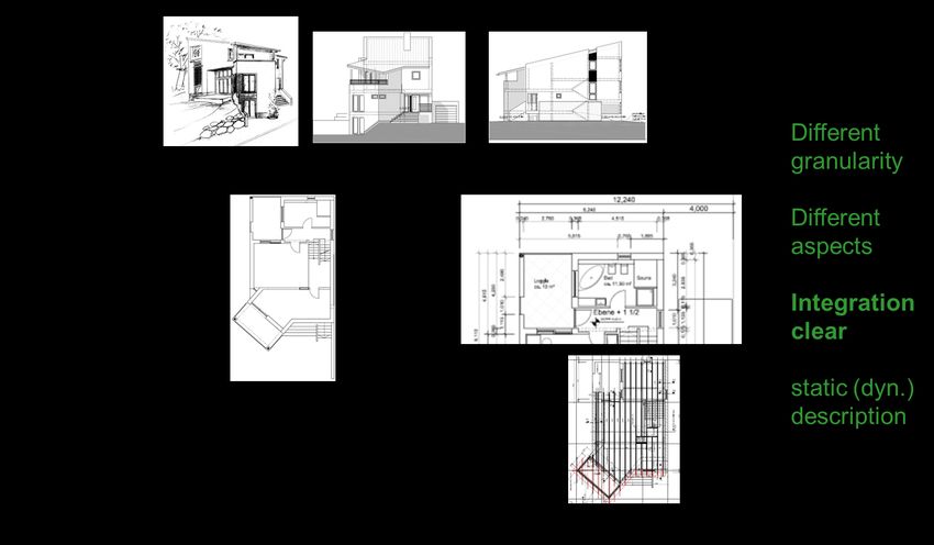
We now explain such a global plan for a well-studied problem, namely to build a compiler
according to the multiphase approach /AL 06/, see fig. 4. We find a control component on
top, starting each of the next level phase components and after its end switching to the next,
namely scanning, parsing (context-free syntax check), static semantics (context-sensitive syn-
tax check), intermediate code generation, optimization, addressing and code generation, and
post-optimization. These are the phases of the compiler, each of which is finished before go-
ing to the execution of the next. The first steps build up the so-called frontend, the last ones
the backend of the compiler. At the bottom we find the data structures which loosely couple
the phase components; namely source text input, tokens (lexical units) list, abstract syntax
tree, attributed tree, intermediate graph, machine code, and optimized machine code. Fig. 4
shows only a part of the compiler.
At the top, we have a functional object module, in the middle, we have functional subsystems,
at the bottom, we find abstract data objects or subsystems. In the case of a language with sep-
arate compilation units (different source code units can be compiled in one compilation run),
the bottom layer consists of abstract data type components, then with slightly different im-
ports, see fig. 3.c.
Patterns (of whatever form) have not the purpose to avoid thinking, arguing, and adapting.
They are just good examples for the architecture education as a basis for discussions, see ar-
guments in section 2. In my opinion, it is a wrong perception that the complete design process
can be organized in form of patterns in a way that the designer only has to find the right and
available pattern to paste it into his/ her architectural design and to combine it with other pat-
terns, which are also available and pasted.
8Fig. 4: The architectural structure of a multiphase compiler: a sketch
Classes of Structures
There are three basic structure classes of software systems (batch systems, interactive sys-
tems, and concurrent systems, the latter mostly also embedded). The above example of a mul-
tiphase compiler is a batch system. A big part of industrial systems is of one of these three
forms. They define standard structures, i.e. global patterns, which are a good foundation, if a
system of one of these three kinds has to be designed.
There can also be mixtures of these basic structure classes, like a batch system for making
complex computations, which, for example, also has an interactive part to change parameters
in an online mode. Then, the main part is batch, that specific part is interactive.
Application domains are business administration (BA), like calculating insurance contracts,
technical computations (TC), as a crash simulation, embedded systems (ES), as automation
and control of a chemical plant, systems programming (SP), like building an operating sys-
tem, etc. The corresponding systems build up application classes. We find batch systems in
BA (monthly salary computation), in SP (compiler), and in TC (crash simulation). All have a
similar global structure, although they belong to different application domains. We find inter-
active systems in BA (cha ge f c me data) or SP (design tool). A concurrent system
can exist in ES, but also in SP, e.g. an operating system. Therefore, from the pattern relevance
point of view, structure classes are more interesting than application classes.
A further extension of the above classifications (structure classes, application classes, etc.) can
be made according to the following dimensions: (a) underlying interaction mechanisms in
systems (e.g. call vs. events), (b) target system platforms (mainframe, personal computer,
network of machines, fine-grained sensor networks), (c) distribution (from bound on one
computer to distributed cloud computing, or even computed on the fly /OTF 20/), and (d) how
computation is done and gained (fixed in program code, interpretation of specifications, se-
lection of rules to be applied, code generated, tables for interpretation, machine learning from
examples).
9Most important of the above classification are structure classes in the sense of formative ex-
periences and examples in education. In fig. 4 we see an example from the systems software
domain which shows the characteristics of batch systems (different computations on the sec-
ond layer put together by a control component on top, which are loosely coupled via data ab-
straction components). This global pattern we also find in different other application domains.
In the same way, we can argue about interactive systems or concurrent systems. Taking also
the application classes and further differentiations into account, may refine the arguments and
deliver further variations of structure classes.
4 Various Further Aspects are Necessary
In section 3, we have discussed syntactical and static properties of architectures, how they are
denoted, and which methodological hints we can find. Now, we discuss further aspects, like
semantics, concurrency, or distribution.
We follow the approach, which we discussed in the architectural design for buildings, see
section 2. We define further refinements, views, and detail levels. However, we do not define
new artifacts, where it is not clear or obvious, where they appear, and how these artifacts are
related to other ones. We rather annotate already existing artifacts. Thereby, we define further
aspects as enrichment of the architecture notation as explained in section 3. Therefore, it is
always clear, where and in which sense the annotations deliver further information and to
which part of the architecture the extended information belongs, see arguments in connection
to fig. 1.
Semantic annotations
Let us go back to the multiphase compiler example (see fig. 4) and let us concentrate on the
scanner part (see fig. 5.a). We assume that the underlying data structures are adt modules,
which enforces a modification of the usability edges, see arguments of fig. 3.c.
We can specify the semantics of component interfaces by pre- and postconditions. For exam-
ple, the scanner transforms a sequence of characters (precondition) into the corresponding
lexical unit (or token, post condition), e.g. an identifier, a word symbol, a delimiter, a literal,
etc. of the underlying programming language.
For the interface of the underlying data types (first part of fig. 5.b) we here use a notation of
functional languages. In our example both are queues, e.g. the scanner writes the tokens at one
side, the parser reads them from the other side. Our example in 5.b shows a stack, more rele-
vant for the parser than the scanner. Usually, we use an Ada-like notation for interfaces in the
textual part of the architecture language.
For this interface, we can give a semantical description in form of algebraic equations (see
/Gu 76, LZ 74/). In the lower part of fig. 5.b we find an algebraic description of the interface
under the assumption that the middle part of the fig. 5.b holds.
In this way, either by pre and postconditions or by algebraic equations we can specify the se-
mantics of single components. The specifications belong to the interfaces of the components
of fig. 5.a.
10fo
FrontEnd
1a: textStream:: 2: scan(textStream, 1b: tokenStream::
1a: open(textSName, 2: scan(tokenStream) 1b: open(tokenSName,
1a: open(ReadOnly) 1b: open(ReadWrite)
fo
3a: textStream::close() 3b: tokenStream::close()
Scanner
2.1, 2.2 2.3
{ { 2.1: eval textStream::
{ { 2.1: isCharAvailable()
adt { { 2.2: textStream::read() } adt
Text { 2.3: tokenStream::write(token) } Token
Stream Stream
a)
b)
Fig. 5: Semantic annotations: Interface specifications and runtime traces
An even more important part of the semantical description is the runtime semantics. Not in all
cases, this part can formally be defined, or it is useful to do it. However, we can define the
runtime semantics at least in a coarse form by traces /Kl 00/, see again fig. 5.a. The trace
specification of fig. 5.a says that Scan has two loops. The inner loop reads characters from
11Text_Input belonging to a token (2.1 and 2.2), and writes the corresponding token to To-
ken_List (2.3). In the outer, loop this is repeated until Text_Input is completely read (2.1).
Before, at the beginning of the scanning process, Text_Input and Token_List are opened (1.a,
1,b). Then, Scan is called from Control. The files are closed at the end (3.a, 3.b).
Traces only show in which order the components are visited. However, they do not show,
what is done during the visit of a component. However, traces are better than nothing. They
correspond to sequence diagrams of UML /BR 05/. Introducing traces within architectural
diagrams avoids defining another artifact, as the sequence diagram, where its contents have to
be related to the diagrams artifact. Following the argumentation of section 2, traces are anno-
tations of the diagram and not a new artifact.
For the scanner of fig. 5.a. we can even give a nearly complete semantical description, not
only the algebraic interface specifications and the coarse trace specification. The behavior of
the scanner component Scan can be described by a finite automaton (or alternatively by a reg-
ular grammar) both defining the lexical syntax of the programming language to be scanned
/AL 06/. This corresponds to the body of the scanner in fig. 5.a. This, together with the inter-
face semantics and the traces, gives a nearly complete and formal semantical description of
the situation described in fig. 5.a. We could also have chosen the parser part or the context-
sensitive analysis (static semantics) part, to argue in the same way.
We should mention that examples of such a formal degree (scanner, parser, context-sensitive
analysis, etc.) are rather seldom. Software systems can depend on taste (like the user interface
of an interactive system), on nonfunctional efficiency parameters (like the runtime parameters
of an embedded system), on restrictions of the underlying hardware (the system is to run on a
special hardware system, a part of the system representing a specific component must be used,
which is programmed in a specific way and only runs on certain remote hardware), and so
forth. In general, formal semantic definitions are in most cases only partially available: some
interfaces, typical traces, formal descriptions only for some components beha i r.
Concurrency annotations
For inherently concurrent problems we need different processes running concurrently, the
competition and collaboration of these processes, and an agreement on how to synchronize in
the case of concurrency and competition for resources and of collaboration. Any sequential
schedule would make the solution harder to understand. It would also avoid that a certain part
can continue, if another part is blocked for some time.
In fig. 6, we see the well-known producer-consumer example as a subarchitechture in graph-
ical form. Producer and Consumer are function objects (two separate single components in
the architecture having the character of a function). In between, there is a Buffer component
as an abstract data object, as only one buffer is needed.
Producer and Consumer have to work independently. Thus, we make both to a process, ex-
pressed by annotations p for the components Producer and Consumer. As both are processes,
we have to define a synchronization for the case of parallel access. It is not necessary to make
the buffer to a process. This synchronization is expressed by the annotation Monitor (mutual
exclusion of all operations of the buffer /BF 95/) as a synchronization specification (in short
sp). The synchronization protocol could also be a protected object of Ada (mutual exclusion
of writers, but parallel readers, if no writer is active /Na 03/), or anything else suitable.
12Again, we see that we can annotate an architecture diagram to express concurrency aspects.
This avoids further and separate artifacts.
p fo p fo
Producer Consumer
... sp = Monitor ado ...
Buffer
mutual exclusion p process has
of all operations own thread
Fig. 6: Annotations for concurrency: processes and synchronization
In the context of concurrency, we might have many producers or many consumers. It is not
reasonable to paste as many - function object and process - components as needed. In some
cases, the number of such processes cannot even be determined at program development time.
For such situations, we introduce function type components, from which we can create as
many function objects as wanted at runtime in the bodies of using components. These pro-
cesses, however, cannot be directly seen on architecture level.
For embedded systems, also the explicit start and stop have to be modeled. Embedded systems
run f e e until they are not explicitly stopped in a controlled way. Analogously, they are
explicitly started in a controlled way. In the same way, emergency handling has to be mod-
eled. Both start/ stop as well as emergency handling can be modeled by the above and further
annotations, which is not discussed here. This altogether explains that the productivity of de-
velopers programming embedded systems is much lower (about one third of the productivity
of sequential systems, as further additional tasks have to be solved (processes and synchroni-
zation, controlled start and stop, and emergency handling).
Component use connections: abstract and concrete
Up to now, a usability edge between a service user component A and a service provider com-
ponent B, offering one or different services, is denoted in an abstract form, see fig. 7.a: There
is a usability relation between both. It can be a local, a general, or an inheritance usability
relation. It says that a service of B will be needed for A. The service use is written down in the
code of the body of A. At runtime, if the corresponding part of the body of A is executed, the
service is provided.
Up to now, we had in mind that the service is realized by a procedure or function of the inter-
face of B and a corresponding call. The service provider may be a fo, ft, ado, or adt compo-
nent. The caller invokes the call, the caller is stopped, and the service is called at the callee
side. If the callee has finished, it stops, and control goes back to the caller.
This abstract situation service of B is used from A can be realized by different mechanisms.
The service might be provided by a coroutine, an entry call, or a task activation. In all these
cases A and B may run in parallel. A and B are synchronized later again, either by program-
ming language mechanisms or by means delivered by the programmer.
13We discuss only three of the many possible forms. In fig. 7.b, we see that the service of B is
activated by an activation signal, naming the service and providing the parameters. After ser-
vice completion a completion signal is sent back, containing eventual result parameters. In the
meantime, A and B may run independently. Also, signals, events, triggers, or interrupts may
be used to handle this service request and service provide situation.
In fig. 7.c, a callback situation is discussed. In the left part, the situation is described: Client A
would like to answer to a state change of B by doing an activity act. This happens, for exam-
ple, if a user is doing something, which has to be answered by the activity act. Instead of poll-
ing (A is always asking B whether the state change has already happened), the operation act is
delegated to the State component. State registers for act and gets a procedure pointer for act.
Situations like this are often interpreted in a wrong way. People say my architecture has
completely inverted . This is not the case: The abstract situation (cf. fig. 7.a) remains the
same, the mechanism for realizing it, however, has changed.
An even more complicated situation we find in event handling systems using broadcasting,
see fig. 7.d (and /Kl 00/). There are components Producer1 and Producer2 producing events e
and e’ which are sent to the Broadcasting Service. The components Comp1 and Comp2, for
example, have registered to get the event e to react by act1 and act2. This corresponds to the
abstract situation that Producer1 and Producer2 may use service act1 of Comp1 and act2 of
Comp2. Corresponding to who has registered at runtime, dynamic use switches are possible,
which can produce a system behavior, which is hard to understand and more confusing than
goto-programming. It should be denoted at development time, who is using whom at runtime.
a) A b)
Service
User
send get signal2
any import signal1 for for
activation completion
B
Service
c) C client C is asking “top callback act via
down” for some state procedure pointer
Client change, then doing act Client when statechange
happens
disadvantages: registering: get
asking often, change procedure delegate
seldomly happens pointer of act activation to that
if State is also component
stchange
changed by other which “knows”
State clients: don’t know State about State
when changes
14d) “dynamic” usability of act1,
act2 of Comp1, Comp2
act1 on e
Producer1
Comp1
event e, e'
events Broadcasting
Service
act2 on e
Producer2 register for
getting event Comp2
event e, e'' e at runtime
Fig. 7: Abstract use and three different concrete mechanisms
Looking on all these situations, we see that the underlying abstract situation of fig. 7.a is real-
ized by using quite different concrete mechanisms for service use. Therefore, we would rather
use the abstract situation of fig. 7.a and provide different annotations, as pc for procedure call,
cc for coroutine call, ec for entry call, cb for a callback, and via bc for via broadcasting. That
has the advantage of abstraction (the underlying abstract situation is to be seen directly) and
flexibility (the used mechanism can easily be changed).
Distribution
A further aspect to be studied now is distribution and deployment. A software system is divid-
ed and deployed on different computers. This is done in the later stages of development,
which starts with virtual and abstract notations.
Fig. 8.a shows the sketch of the architecture of an interactive business administration system,
which was reengineered from a monolithic mainframe system /Cr 00/, by introducing subar-
chitectures (inner details not shown in fig. 8.a), which are clear areas of concern: The control
part for managing the dialog, the UI part to keep all UI details away from the inner system,
the main application parts determining the functionality of the interactive system, and the un-
derlying database subsystem, which hides data and schema details. Reengineering via subar-
chitectures of clear concern has made the system to consist of loosely coupled parts as shown
in fig. 8.a.
We now decide to put these parts on different machines: the UI part on intelligent work-
stations, the control, the main business functions and the data handling on function and data
servers, by reasons of security or redundancy. The lines of separation are given as an annota-
tion in fig. 8.a, the used distribution infrastructure, here Corba /COR 20/ for remote procedure
calls, is also annotated.
Fig. 8.b shows the technical solution for Corba /Kl 00/: On both sides of a cutting line and
distribution, technical components are introduced, which are either provided (RPC Basic Ser-
vices, Marshalling, Unmarshalling) by Corba or are generated by Corba from a specification
(client stub and server stub). They provide that the procedure call is transformed into a data
stream, sent over a connection, put together on the server side, and is executed on the server
15side. Similarly, it finds the way back. There are various distribution infrastructures, working
similarly as Corba, which can also be used, e.g. Remote Method Invocation for Java /WR 96/.
a)
Control
CORBA
main application
Business
components free of
Functions
all presentation presentation and storage
details here
data server,
thin Underlying
UI all storage
client Data Base
details here
b)
Client Client
annotations for
RPC infrastructure,
CORBA e.g. CORBA
dt fo
Server Server
Server
Stub Stub
fo fo
annotations for Unmar-
Marshalling Server
distributed call, shalling
e.g. RPC
RPC Basic RPC Basic
Services Services
client – side server – side
components components
Fig. 8: Distribution characterization and its realization by making use of a distribution infra-
structure
Two remarks at the end of this short discussion: (a) Again, it should be noted that the more
abstract solution with annotations says more than the detailed technical solution. It also al-
lows to easily change the annotations and to use another distribution infrastructure. (b) Dis-
tributing software over different machines might introduce some technical concurrency. For
example, if different main application functions run in parallel and have access to a data serv-
er. Then, these accesses have to be synchronized.
Styles: Integrating different notations
In /GS 94/ different notations for architectures have been introduced for specific integration
situations occurring in software construction. They were called architectural styles. Reading
16about these styles creates the impression that any of these styles introduces a separate notation
and that these different notations have nothing to do with each other. They all lead to separate
architecture worlds.
/GS 94, SG96/ introduce different architectural notations, namely (a) pipeline, (b) data flow
architectures, (c) loosely coupled systems, and others. We only discuss pipeline architectures
here and leave the other style discussions to a separate and forthcoming paper.
We express pipeline architectures by the concepts we have introduced so far. Fig. 9.a gives an
example of such a pipeline architecture. There are three components f1 to f3, executed one
after the other, i.e. the output of f1 is the input of f2 and so forth. They make up one bigger
component F, where the input of which is directed to f1, and the output of f3 is the output of F.
There are mainly two possibilities for the semantics. The first, here called discrete case, works
in the way that F takes the input, then executes the pipeline - functions f1, f2, and f3 - and
outputs the result. Then, F takes the new input. In the second possibility, called continuous
case, the input of F is passed to f1. After f1 has produced its result, the next input of F can be
taken by f1. Thus, in this case, three inputs of F can be taken and passed to f1, before the first
output of f3 gives the first output of F.
Fig. 9.b gives the simulation for the discrete case. The control component takes the input
from input, then controls the sequence of executions f1 to f3 , where for every fi an output is
passed back to Control. At the end of this sequence, the output of f3 is passed by Control as
output of F.
Fig. 9.c simulates the continuous case. Now f1, f2, and f3 work in parallel, so they are made
to processes, see annotations p. The input is taken from f1, passed by an entry call to f2, and
f1 takes the next input. It should be noted that further semantics are possible, which can also
be simulated.
What we have demonstrated for pipeline architectures, can also be shown for the other style
notations, as data flow architectures, loosely coupled architectures, and others. Thus, all these
different notations are traced back to the modular notation introduced above in section 3.
Therefore, the style notations - like pipelining - are not really new and completely different.
We can use them for architecture modeling, just as abbreviations for situations we can express
otherwise in the standard notation.
a) F
input f1 f2 f3 output
the result of f1 is input to f2; the result of f2 ist input to f3; ...
17b) execute pipe c) execute pipe
completely in parallel
discrete continuous
case Control case Control
2.1 2.2 2.3
p p p p p p
f1 f2 f3 f1 f2 f3
ado ado ado ado
Input Output Input Output
take next input when results to next
f1 has completed component by entry
Fig. 9: Pipeline architecture style is traced back to the standard notation
Thereby, we found another integration dimension: We have integrated different notations by
aci g hem back a standa d notation. Furthermore, as the semantics of the style architec-
tures can vary from paper/ book to the next, we can define the semantical differences appro-
priately.
5 Relations between artifacts and putting together
Hierarchies and other relations
The architectural configuration of a software development process consists of the following
artifacts, in the sense all is part of : overview diagram, architectural diagrams of parts of the
overview diagram, architecture diagrams of subsystem bodies, text artifacts for component
interfaces and also for detailed usability relations. The examples of this paper were mostly on
diagram level and there on the level of overviews. The architectural configuration is an organ-
ization relation for c llec i g e e hi g ha i eeded for architecture modeling.
Within artifacts, we find internal diagram hierarchy relations for expressing locality, layer-
ing, and inheritance within a diagram. S c e ela i a i l cal , l ca ed a ce ai
ab ac i la e , i a e abli h underlying relationships, from which we select corre-
sponding usability relations (import relations) between components, a l call able , a-
ble be ee la e , able i hi a i he i a ce c e .
There are hierarchy relations for delivering details: For example, from a shorthand notation
of a subsystem to its details (the aggregated interfaces, the architecture diagram for the body),
from a module to its textual description of the interface, and also to the structure and usability
relations as text clauses. The relations are from a diagram to a more detailed diagram, or from
a diagram to its corresponding detailed text. We also find details from an annotated diagram
to the details of the annotation in another diagram, so here from diagram to diagram.
Some of the relations come from/ go to the outside of the architectural configuration: (a)
From a requirement to the parts of the architecture realizing this requirement, or vice versa
from architectural items to the requirement items they belong to. We also find them (b) from
architectural items to the realization/ programming/ coding items or vice versa, (c) from archi-
tectural items to the management items organizing the work or vice versa, (d) from architec-
tural items to quality assurance items or vice versa, (e) from architectural items to documenta-
18tion items explaining the decisions or vice versa. All these relations facilitate to understand,
realize, or manage the architectural configuration. They were not regarded in this paper, see
/Na 96/.
The architectural configuration is the center or the most important part of the overall configu-
ration, which also contains parts for requirements, realizations, management, quality, and
documentation. The architectural configuration contains the main decisions, the long-term
quality properties, and the organization of the whole development process. To a big part the
overall configuration is determined by the decisions in the architectural configuration. The
overall configuration contains all documents/ artifacts of the development process, together
with corresponding relations inside and between the documents/ artifacts.
These relations split into different fine-grained relations inside and outside of the architectur-
al configuration and within the overall configuration. Examples are: (i) For an interface item
of a module which is a procedure header to the procedure definition in the programming part,
(ii) for a module to its explanation in the documentation, (iii) for a module inside the body of
a subsystem to the specific quality assurance measures taken for this module, (iv) from an
annotation in a diagram to the corresponding detail information, etc. These fine-grained links
/Na 96, NM 08/ are very important and have to be obeyed in a program systems develop-
ment. In a usual tool suite, there is no proper support for them.
Different languages are used
o Diagrammatical languages for overviews, textual languages for details. In this article, we
concentrated on the graphical languages.
o Formal languages, for the specification of an interface are used, or informal ones to sketch
the purpose of a component in the documentation.
o Architectural style notations stand for abbreviations of architectural situations as sketched
in section 4.
o Various forms of consistency relations (context-sensitive syntax) appear inside the archi-
tectural configuration.
o Different forms of method rules and patterns say what and how to design.
o The architectural languages consist of different parts along with a historical development
/Al 78, Le 88, Na 90, Bö 94/ and this paper.
Usable for different architectural approaches, applications, and problems
The approach can be used in different ways:
Functional decomposition with data abstraction, see the compiler example. It can also be
used for layers, e.g. for different layers of data abstraction. We can model inheritance hi-
erarchies.
It can be used in OO approaches by some form of backward simulation: fo and ado
components as abstract classes, inheritance inside, and layering between components out-
side of inheritance.
Style notations can be introduced as abbreviations of modular situations, for pipeline, data
flow, or loosely coupled systems.
Structure classes (batch systems, interactive systems, and embedded systems) are charac-
terized by global patterns. Further differentiation, e.g. for application domains, etc. (see
discussion in section 3) can be expressed.
19The approach can be used for new development, for reverse and reengineering, for
maintenance, and for extensions of systems. It can even be used for systems written in old
programming languages.
Remarkable experience in architecture modeling
The software architecture approach, presented in this paper, has been used for research, de-
sign, and development tasks of remarkable size. We mention only some of them here.
The main activities were tightly integrated tools for software development in the IPSEN pro-
ject /Na 96/, tools in chemical engineering in the IMPROVE project /NM 08/, and design
tools for mechanical engineering /NW 99/. In all these cases not only tools for architectural
design were regarded. Also, documentation, management, and requirements engineering have
been studied. Furthermore, specialized integration tools to keep fine-grained relations be-
tween artifacts consistent to each other have been studied and implemented.
But there are also other and specific applications, as technical applications containing expert
systems /Ba 95/, reverse and reengineering in business administration /Cr 00/, reengineering
of telecom systems /Ma 05, Mo 09/, tools for authoring /Ga 05/, and for automotive /Me 12/,
and smart homes /Ar 10, Re 10/. Furthermore, in a project aiming at new concepts for a non-
standard database system in the systems programming domain, there are many architectural
descriptions /Ba 00/.
Finally, in /KN 07, Kr 07/ we came back to the architectural design of buildings. We extended
CAAD systems to give specific support for the conceptual design of buildings and to special-
ize this support for specific classes of buildings, like e.g. medium size office buildings. A
knowledge engineer architect develops this knowledge, which is then taken up by a traditional
architect. Buildings (bridges, cathedrals) or parts of it are used as role models for good soft-
ware design. In /Na 19/ the design of gothic cathedrals and its relation to software architec-
tures was worked out for the first time.
6 Summary and Open Problems
Integration w.r.t. different dimensions
Summary of the static part in eg a ion a ec with the following dimensions: We have
introduced different kinds of components, for functional and for data abstraction, as objects
(fo, ado) or as types (ft, adt). Also different kinds of relations were introduced, namely struc-
ture and usability relations. Therefore, different kinds of construction principles can be ap-
plied: locality, layers, and object orientation, different kinds of consistency relations from the
context-sensitive syntax of the underlying design languages on one hand, and from the view-
point of good and clear use of the languages on the other. These method rules (patterns) are of
different kinds: patterns, as it should be, from wrong to right, from specific to more general
(as object to type), from abstract and clear to detailed or efficient, etc. We have also intro-
duced components of different size, modules or subsystems, or units of the design languages:
from interface specs of modules, to complete modules, to pairs of modules with relations, to
subarchitectures, to subsystems containing subarchitectures, to complete architectures. Final-
ly, the approach unites design and parametric design (genericity). This all was presented in
this paper (section 3) using different languages, graphical and textual (as discussed in section
5).
20Summary of further aspects: Further aspects have been introduced which result in annotations
of the design artifacts, mostly together with further refinements of the artifacts in form of ad-
ditional details in the same or in other artifacts. We introduced semantical notations for inter-
face specifications, runtime traces, or behavioral specifications, e.g. in form of finite automa-
ta. Concurrency annotations denote the information for processes and synchronization proto-
cols: Further parts for start/ stop of the system and emergency handling can be added for em-
bedded systems. For abstract connectors (request and supply of services) different mecha-
nisms can be introduced, from coroutine, signal, trigger, interrupt to event handling by broad-
cast. The distribution of a system can be annotated by distribution lines and annotations, or in
detail by additional components and connectors of an underlying distribution platform. All
these aspects introduce detailed views to more abstract ones. Thus, abstract and detailed views
can be regarded to be integrated. In many cases, the detailed views will be developed and
studied only by specialists or/ and afterwards.
Different notations from architectural styles, as pipeline, data flow, loosely coupled systems,
etc, are abbreviations of our architectural notation. Therefore, they can be used together with
the standard notations without leaving the conceptual framework of architecture modeling, as
introduced in this paper. Thus, we have integrated different architectural notations.
As already discussed, the architecture is the essential structure of the development process,
used for decision making, arguing about structures, realization, extensions, and maintenance,
explaining the structure and concepts, and also methodologies to build the system, therefore
integrating essential activities. The architecture is composed of different views regarding dif-
ferent aspects, with more or fewer details. The relations between different artifacts and units
of artifacts should be clear. All the stakeholders of a system development have to do with the
architecture in different degrees of detail, for writing or verifying an artifact, in other cases to
roughly explain and coarsely understand it.
The architecture is a configuration of diagrams, detailing texts, annotations within a descrip-
tion, references to corresponding more and detailed elaborations. A part of this configuration
is directly devoted to architectural views and aspects. Other parts and outside of the architec-
tural configuration belong to quality, documentation, and management of the development
process or are derived from the architecture, as the program code. In total, the architecture
integrates different aspects and corresponding artifacts or is the center for integration for other
aspects.
This architecture configuration is a part of the overall configuration of the system to be built,
extended, or maintained. The overall configuration contains further artifacts for requirements
engineering (outside views, the system to be developed has to follow), as well as artifacts for
the realization (programming, implementation). The architectural configuration is the essen-
tial part of the overall configuration. By the way, this kind of overall configuration we find in
all engineering domains: outside view for requirements, essential internal view, from an ab-
stract logical level (conceptual modeling) down to the level of describing the essence of the
system as it is delivered to the customer /Na 90, Na 96, NM 08, NW 99/, and adding all de-
tails of realization (detail engineering). In this paper, we concentrated on architecture model-
ing, forgetting upwards about requirements and also downwards about detail engineering. We
only regarded the links from and to architectural units. The overall configuration corresponds
to the BIM model for buildings, cf. section 2. We could also say, the overall configuration is
our product information model for system development.
21You can also read