Assembly manual Black Snapper L Pro Status: September, 2014 - Assembly manual Black Snapper L PRO
←
→
Page content transcription
If your browser does not render page correctly, please read the page content below
Assembly manual
       Black Snapper L PRO

Assembly manual Black Snapper L Pro
       Status: September, 2014

                 Seite 1 von 16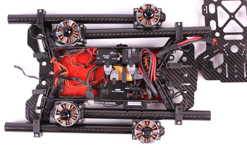
Assembly manual
Black Snapper L PRO
Assembly of the booms
In the kit, booms with 2 different lengths are included. The shorter booms have to be mounted to the front end of
the aircraft.
Before mounting the motors, please make sure that the threads for the motor wires point to the center frame.
When you finally tighten all screws, you will have to fine-adjust the rotation of the boom.
Do not tighten the screws firmly already. You
will have to loosen them again when you
adjust the vertical alignment of the motor axis.
The mounting holes for the landing
skids have to face down.
Make sure that the asymmetrical holes in the
motor plate match the threads in the motor
before you insert the cables.
Nicht im Lieferumfang
M3x15mm Distanzbolzen
am besten aus Metall.
Werden bei H3-3D Gimbal benötigt!
Seite 2 von 16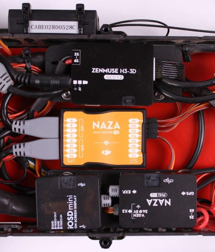
Assembly manual
                                     Black Snapper L PRO

 Push the end cap into the tube
  before you attach the motor.

First, you have to thread the motor cables through the whole length of the boom. Then you have to bend the cables
                 back and thread them through the holes on the side using a pair of angled tweezers.

Please use heat shrink tube to protect the motor cables from the sharp edges. Avoid heating up the boom material!

                                                 Seite 3 von 16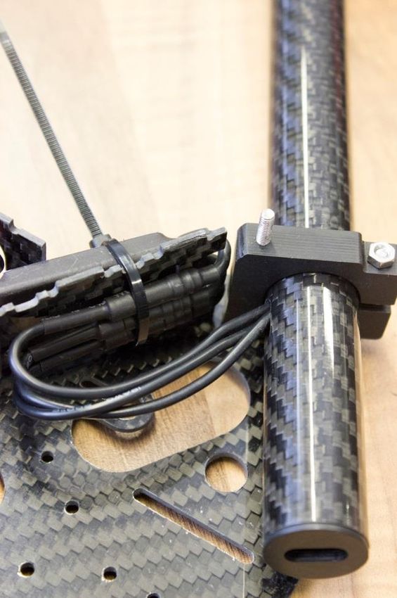
Assembly manual
Black Snapper L PRO
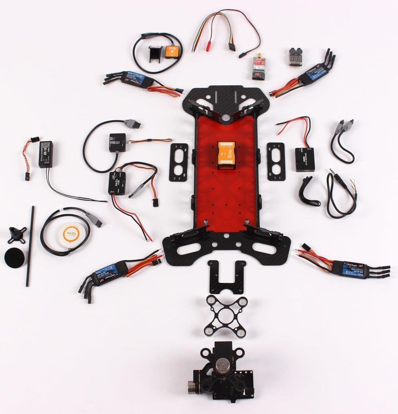
Overview over the compontents which have to be installed in the main frame
Seite 4 von 16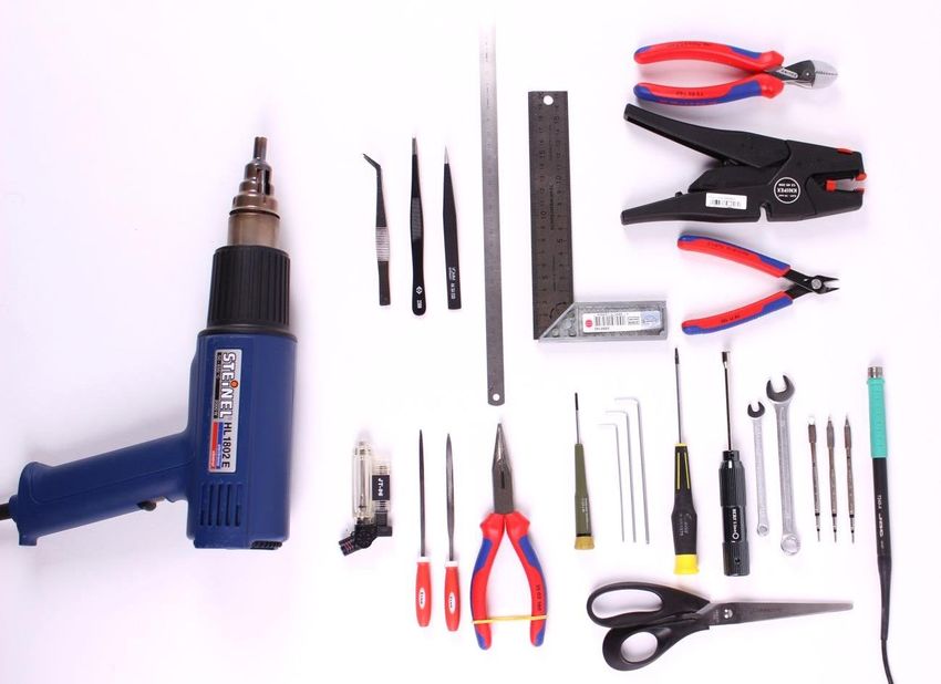
Assembly manual
Black Snapper L PRO
Installation of the ESCs, Naza V2 PMU and Zenmuse GCU in the frame and soldering of the y-leads
Please mount the ESCs and the ESC wires like shown in the picture. The cable tie holds both ESC and the wires on the
mounting plate.
In this position, the folding mechanism can work unobstructedly and won’t damage the wires. The wires are almost
at the turning point of the boom, so they are protected from getting weaker or worn. If you mount the ESCs in a
different way, you risk damaging the wires!
Before you solder the cable harness, you should test fit the components into the frame. Doing so, you can measure
the approximately required cable length und cut them.
Seite 5 von 16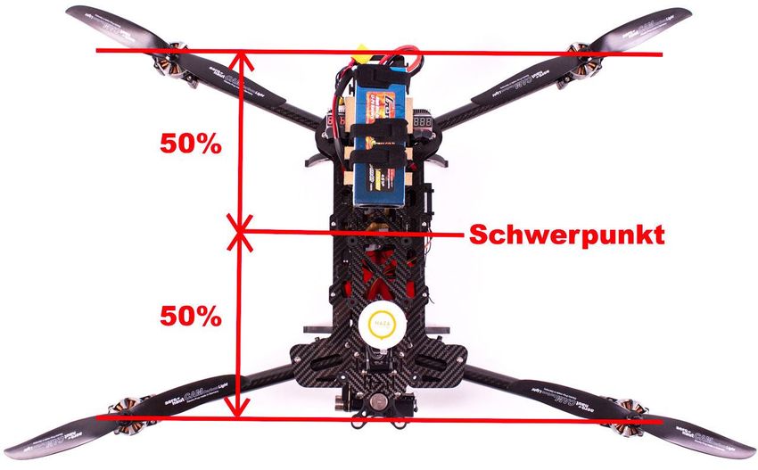
Assembly manual
                                  Black Snapper L PRO

Cable harness:                                               Solder the plug AFTER threading the cable
                                                             through the center frame

Power Molex (video TX)

             BEC plug (reserve)

                                                                         BEC plug (reserve)

                                            Seite 6 von 16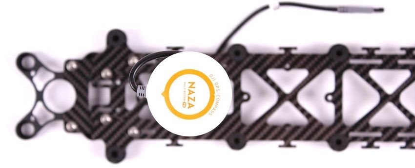
Assembly manual
Black Snapper L PRO
Installation of the NAZA V2 MC and of the RC receiver in the frame
- Before you install the receiver and the NAZA V2, you can connect them with the cable/s to get an
impression of the possible distance and where the receiver could be mounted.
At this point, you have to decide whether you would like to use a traditional receiver and connect each
channel directly, or whether you want to use a PPM receiver using only one cable with sum signal.
See the NAZA V2 wiring overview on page 6 of the English manual:
http://www.dji.com/product/naza-m-v2/download
- When mounting the NAZA V2, please make sure it is placed exactly in the middle of the frame and in the
CoG of the aircraft. The small arrow on the MC must point to the nose of the aircraft (to the gimbal) and
the line must be parallel to the middle axis of the main frame.
Gimbal /
aircraft nose
Seite 7 von 16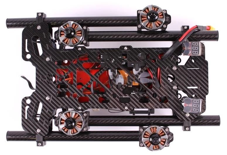
Assembly manual
Black Snapper L PRO
Checking the direction of the motor rotation
Attach the booms including motors but without propellers to the frame and connect the three motor cables and the
ESC signal cable.
The motors have to be fixed in upright position and there shouldn’t be any loose objects around them.
Now it is time to adjust the first settings in the Assistant Software. The ideal power source is a regulated power
supply unit with a current limit set to 3 amps.
Choose “Basic“ – “Aircraft“ and then select “QuadRotorX“.
In the following, please click the “Motor Test“ button.
Confirm the warning message with „agree“.
Seite 8 von 16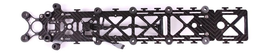
Assembly manual
Black Snapper L PRO
Checking the rotation direction
Now you can activate the fixed motors with a click on each button from “M1” to “M4“.
In case the rotation direction is different from the displayed image in the Assistant, simply swap 2 of the 3 motor
cables.
Seite 9 von 16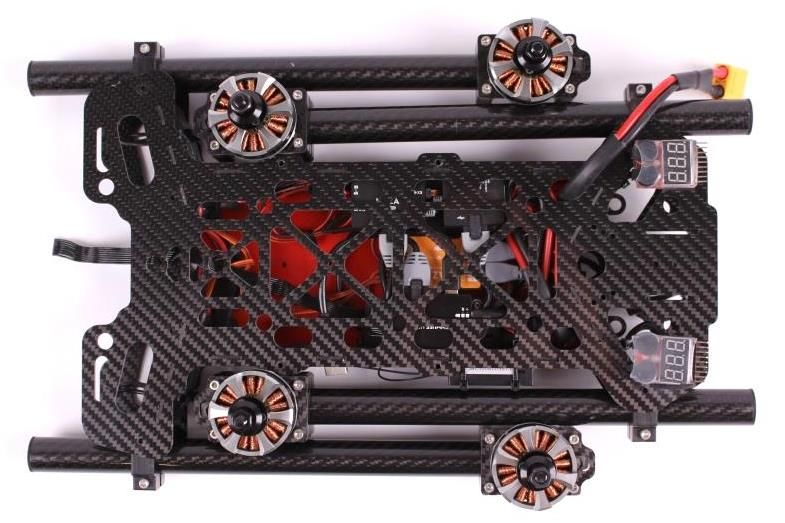
Assembly manual
Black Snapper L PRO
Installation of the booms and assembly of the frame – Schematic illustration:
- Please check all your components for available software updates before you proceed with the assembly.
Seite 10 von 16Assembly manual
Black Snapper L PRO
Installation of the booms and closing the frame
The boom pipe should end exactly at the edge of the
inner snapping part. When you adjust the vertical
alignment of the motor axis, please turn the boom first
until the cable holes are facing the ESCs. Make sure that
the hole doesn’t point upwards or downwards and that
the cables can’t get squeezed.
After this, mount the landing gear and adjust the motor
alignment using a 90° angled tool.
Before you fit the top frame plate on the side walls,
make sure that the side walls fit snugly into the bottom
plate and that no wires are squeezed. This process
requires a bit patience.
Please mount the snapping
parts and joints using the
following parts: 1 screw, 1
nut and 2 washers. The
washers have to be placed
on the outside of the
frame.
Battery plate with H3-3D gimbal, GPS holder and battery plate extension for lightweight batteries
(optional)
Seite 11 von 16Assembly manual
Black Snapper L PRO
It is recommended to protect the GPS cable part which is threaded through the plate from damage with a piece of
heat shrink tube.
The final position of the gimbal mount and of the battery plate extension can only be adjusted when the aircraft is
fully assembled, so you only need to tighten the screws slightly at this point.
The arrow of the GPS antenna must point exactly to the front of the aircraft. Arrow and notch on the antenna have
to be exactly parallel to the middle axis of the center frame.
Mount the battery plate to the frame using the rubber dampers, attach the gimbal and plug the cable in. You can
also use the Anti Drop or cable ties to prevent the gimbal dampers from slipping out.
Seite 12 von 16Assembly manual
Black Snapper L PRO
When the frame is closed, the CoG of the copter needs to be adjusted by moving the battery, battery extension plate
and the gimbal mount. Tighten all screws when you are finished.
From the mechanical point of view, the aircraft is now ready for the maiden flight.
The final step is to adjust the final settings in the Naza V2 Assistant software. You can find a screenshot of gain
values for reference at the end of this manual. Furthermore you have to enter the position of the GPS antenna, set
the low voltage values and RC transmitter switches. Please see the Naza V2 manual for further information.
Seite 13 von 16Assembly manual
Black Snapper L PRO
List of the components used
1640 Black Snapper Pro L - foldable carbon fiber quadcopter kit
0867 DJI - NAZA V2 + GPS multicopter flight control
0519 Maytech GF-MT30A with SimonK Firmware
0635 T-Motor GF MT4006 -13 740KV, 40cm cables
0522 Distance collar 8mm auf 6mm
1380 Aeronaut CAMcarbon light propeller 12x5 R (CW)
1381 Aeronaut CAMcarbon light propeller 12x5 L (CCW)
0844 T-Motor shaft adaptors 6mm CCW for MT28--series, MT40-- series and MT3506 (PA006)
0504 RC receiver GR-16 HoTT
1540 DJI Zenmuse H3 3D ( 3 axis) for multicopters
1003 DJI - iOSD Mini
1036 Black Snapper – Landing gear set
1037 Black Snapper – Boom landing skid set
0188 5,8 GHz ImmersionRC 25 mW A/V video transmitter
0539 5,8 GHz zirkular ImmersionRC antenna set SPW - spiroNET
1053 GPS holder foldable aluminum/carbon fiber
0959 Lipo saver with votage display and alarm sound
1676 Black Snapper L PRO - DJI Zenmuse H3 3D mounting adaptor carbon fiber
1218 Black Snapper – Battery plate extension for lightweight batteries
1123 GoPro Hero3 or Hero4
Seite 14 von 16Assembly manual
Black Snapper L PRO
Recommended tools
Hot air gun or Micro Blazer / needle-nosed pliers / scissors / slot screwdriver 2mm /
hex wrench 1,5; 2; 2,5mm / hex screwdriver 2mm / socket wrench 5,5mm / flat spanner 5,5mm & 10mm /
soldering station with various tips / tweezers angled, flat & pointed / 30cm steel ruler / 90° angled tool / cutting
pliers / cable stripper / small cutting pliers / regulated power supply / cable ties / different sizes of heat shrink tube /
Velcro tape / 4mm2 wires black & red 50cm / XT90 connectors male/female
Seite 15 von 16Assembly manual
Black Snapper L PRO
Example gain value settings for our recommended setup
Seite 16 von 16You can also read