Bachelor Thesis - Diva-portal.org
←
→
Page content transcription
If your browser does not render page correctly, please read the page content below
Bachelor Thesis
 Computer Science and Engineering & Intelligent
Systems

Smart Dressing

Towards Digitalized Wound Monitoring

Computer science and engineering &
Electrical engineering, 15 credits

Halmstad 2021-06-15
Julia Anderberg, Alina Uddin
                                              HALMSTAD
                                            UNIVERSITY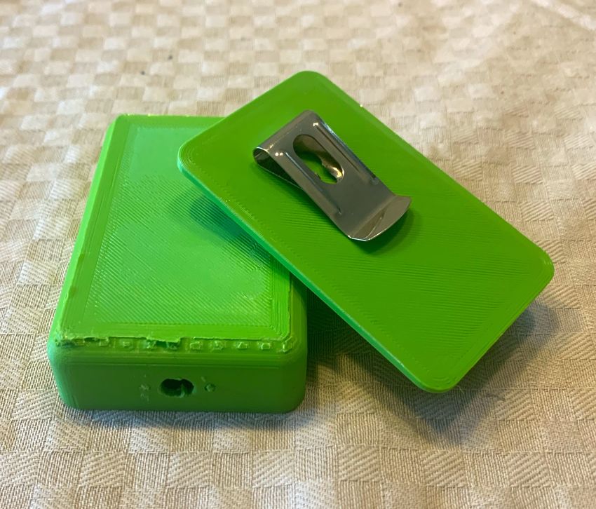
Julia Anderberg & Alina Uddin: Smart Dressing, Towards Digitalized
Wound Monitoring

ABSTRACT

Digitalization of health care is one of the most prioritized areas within
the healthcare community. Within chronic wound care, considered
the silent epidemic and one of the most expensive and unsolved bur-
dens to the medical system, the next generation of wound dressings
with abilities of real-time monitoring has attracted considerable atten-
tion. The most frequent complication in a chronic wound is infection.
Infection in chronic wounds not detected in time can lead to amputa-
tion of limbs or even death. Real-time monitoring of chronic wounds
gives possibilities to detect infection in early stages and avoids un-
necessary wound dressing changes since the change disturbs heal-
ing. Here, a prototype of an infection detection dressing has been
designed. Flexible and biocompatible sensors for wound temperature
and wound pH level has been used. Measured values are transmit-
ted via Bluetooth to an Android smartphone Application where mea-
sured values are displayed together with a Wound Status Bar. Based
on the Arduino Nano electronics platform, the system connects to
the smartphone application, measures and displays measured values,
and the wound status bar responds correctly to changes in the mea-
sured values. The prototype developed highlights questions that need
to be solved when moving into the next generation of real-time mon-
itoring wound dressings.

                                                                      iii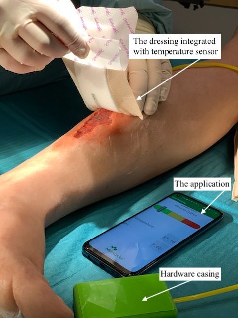
S A M M A N FAT T N I N G

Digitalisering av sjukvården är ett av de mest prioriterade området
inom den medicinska utvecklingen. Inom området behandling av kro-
niska sår, som anses vara en dold sjukdom och är en av den mest
kostsamma och olösta bördan inom sjukvården, har utvecklingen av
nästa generations sårförband som ska övervaka ett kroniskt sår i re-
altid uppmärksammats och skapat ett stort intresse. Den mest vanliga
komplikationen i ett kroniskt sår är att såret blir infekterat. Om en in-
fektion i ett sår inte blir upptäckt och behandlat i tid kan det leda
till amputering av lemmar och till och med död. Med ett real-tids
övervakande förband kan en infektion upptäckas i tid men kan även
förhindra onödiga byten av förband då även förbandsbyten påverkar
det kroniska sårets läkning. Genom att integrera flexibla och biokom-
patibla sensorer i ett förband som mäter temperatur och pH-värde
i såret, och sedan skicka sensor data via Bluetooth till en Android
applikation där data visuellt visas, har en prototyp av en infektions
detekterande enhet utvecklats. Projektet resulterade i ett system där
sensorerna och en Bluetooth modul kopplades till en Arduino Nano.
Sensor data skickas via Bluetooth till en Android applikation där
mätvärdena visas och även en indikator som uppdateras beroende på
ändringar i sårets status. Framtagningen av protypen har genererat
viktiga frågeställningar att överväga när nästa generations real-tids
övervakande förband ska utvecklas.

                                                                       v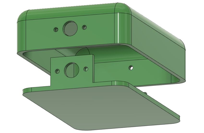
CONTENTS

1   introduction                                                            1
    1.1 Problem Definition and Purpose . . . . . . . . . . . . .            2
    1.2 Requirements . . . . . . . . . . . . . . . . . . . . . . . .        2
    1.3 Project Scope . . . . . . . . . . . . . . . . . . . . . . . . .     2
2   background                                                              5
    2.1 Chronic Wounds . . . . . . . . . . . . . . . . . . . . . .          5
    2.2 Clinical Background . . . . . . . . . . . . . . . . . . . .         6
    2.3 Biosensors . . . . . . . . . . . . . . . . . . . . . . . . . .      6
    2.4 Arduino Platform . . . . . . . . . . . . . . . . . . . . . .        8
    2.5 Transmitting Devices . . . . . . . . . . . . . . . . . . . .        8
        2.5.1 Bluetooth . . . . . . . . . . . . . . . . . . . . . .         8
        2.5.2 NFC . . . . . . . . . . . . . . . . . . . . . . . . .         9
    2.6 Operating Systems . . . . . . . . . . . . . . . . . . . . .         9
    2.7 Fusion 360 . . . . . . . . . . . . . . . . . . . . . . . . . .      9
    2.8 OrCAD . . . . . . . . . . . . . . . . . . . . . . . . . . .        10
    2.9 Ongoing Initiatives . . . . . . . . . . . . . . . . . . . . .      10
3   security in development of android application                         11
    3.1 Permissions . . . . . . . . . . . . . . . . . . . . . . . . .      11
    3.2 Intent . . . . . . . . . . . . . . . . . . . . . . . . . . . . .   12
4   method and materials                                                   13
    4.1 The Sensors . . . . . . . . . . . . . . . . . . . . . . . . .      13
    4.2 Temperature Measurements . . . . . . . . . . . . . . .             13
    4.3 pH Measurements . . . . . . . . . . . . . . . . . . . . .          14
    4.4 Connection of the Temperature Sensor . . . . . . . . . .           15
    4.5 Values in Arduino IDE . . . . . . . . . . . . . . . . . . .        15
    4.6 Wireless transmitting device . . . . . . . . . . . . . . . .       16
    4.7 Development of the Smartphone Application . . . . . .              16
        4.7.1 Wireless Connection . . . . . . . . . . . . . . . .          17
        4.7.2 Collection of Data . . . . . . . . . . . . . . . . .         17
        4.7.3 Wound Status Indicator . . . . . . . . . . . . . .           17
    4.8 The Wound Dressing . . . . . . . . . . . . . . . . . . . .         17
    4.9 Prototype Test and Evaluation . . . . . . . . . . . . . . .        19
5   results                                                                21
    5.1 Schematic Diagram . . . . . . . . . . . . . . . . . . . . .        22
    5.2 Hardware Casing . . . . . . . . . . . . . . . . . . . . . .        23
    5.3 Android Application . . . . . . . . . . . . . . . . . . . .        24
6   discussion                                                             27
    6.1 Security . . . . . . . . . . . . . . . . . . . . . . . . . . . .   28
    6.2 Ethics . . . . . . . . . . . . . . . . . . . . . . . . . . . . .   28
7   conclusion                                                             29
    7.1 Future Development . . . . . . . . . . . . . . . . . . . .         29

                                                                           vii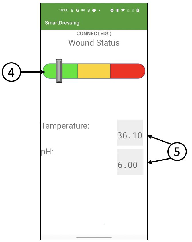
viii      contents

       bibliography     31
       a android code   35
       b arduino code   37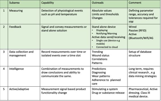
INTRODUCTION
                                                                            1
The evolution of computers is progressing rapidly. The expansion
has gone from being a desktop PC to be portable miniature comput-
ers with implemented sensors and internet-connected devices, just
under a more familiar name, smartphones. The cellphone has pro-
gressed from being a device to make calls and send a text to become
a wearable computer. This advanced technology has opened up the
possibility for digitalization.

   Digitalization of health care is one of the most prioritized areas in
the health care community due to the potential to reduce cost. With
an increasingly aging population and a need for decentralization of
health care and remote, at-home, and bedside monitoring, there is a
growing need for products with advanced capabilities that can pro-
vide data suitable for the planning of care and clinical diagnostics.
Digitalization of health care drives a need for medical device wear-
ables that monitor relevant data for supporting decisions in interven-
tions, treatments, and diagnostics[1].

   On the consumer side, there are many wearables monitoring every-
thing from heart rate, ECG and movement to blood oxygene levels
and sleep patterns. In professional health care, wearable devices are
a commodity. Examples are hearing aids, blood glucose monitoring
devices and pacemakers. The market for wearables within chronic
wound care is still very immature, and there is no product available.
However, there are various patent applications describing solutions
for wearables monitoring chronic wounds. The majority of them are
from the US. Most active are the companies Smith&Nephew, Elwha,
and Hill Rom Services[2].

   Chronic wounds are considered one of the most important un-
solved and expensive medical burdens[3]. A wound is defined as
chronic when it has not healed within four (4) weeks to three (3)
months. It is often called the silent epidemic and affects a large amount
of the population, in the US 6.5 million people and in the EU between
1.2-2.0 million people[4].

   A chronic wound impacts health and quality of life in devastat-
ing ways. A wound that is open for a long time has an increased
risk of developing complications such as infection and tissue necro-
sis, leading to amputation of limbs or even death if not treated in time.

                                                                       1
2 introduction
To avoid disastrous outcomes, early detection of infection is critical.
Today chronic wound treatment is based on usage of advanced ban-
dages called wound dressings, consisting of layers of different mate-
rials keeping a healing promoting environment within the wound[5].
The project aim has been to develop an early concept of an ac-
tive wound dressing for real-time monitoring of a wound’s status,
whether there is an indication of infection or not. Status data is cap-
tured by, in the wound dressing, integrated biosensors measuring
infection-relevant biomarkers. This enables different choices for data
management, such as local or cloud storage, trending, and diagnos-
tics.
1.1 problem definition and purpose
The company sees a general user need in having a dressing that
can detect malignant signs in chronic wounds. Digitalized dressings
measuring biological parameters indicating the status of a chronic
wound is one identified route forward to meet these user needs. To
increase knowledge around biological parameter sensors and connec-
tivity technologies, the assignment from the company was to develop
an early prototype of a dressing that could measure and display rel-
evant data. The purpose of this was to investigate the digitalization
of the wound care landscape and identify a conceptual idea of what
biomarkers to measure and how to display data.
1.2 requirements
The project task is to define a concept for a Chronic Wound Care
monitoring device. Based on literature research and discussions with
the company, the following requirements for the project have been
identified:
• Decide biological parameter to measure
• Enable wireless data transmission
• Enable live monitoring of selected parameters
1.3 project scope
Smart dressing technology can be divided into five subareas. Measur-
ing, feedback of signals, data collection, logic and intelligence, and ac-
tive/adaptive. In Figure 1, the capabilities for the different subareas
are summarized. The concept will only be tested in laboratory con-
ditions and not on actual patients. The project scope is also marked1.3 project scope 3
green in Figure 1. In Figure 2, the digital ecosystem for a Smart Dress-
ing is outlined, and the yellow box indicates what parts the project
will focus on.
Figure 1: Smart dressing technology divided into five subareas. The project
scope is within the green colored rows.
Figure 2: Graphic description of the concept
As shown in Figure 2, the project is limited to the development of
the real-time measurements of biological parameters and reading and
displaying smartphone application. The application can be developed
with different user interfaces and displays the relevant data depend-
ing on the user needs. This project will focus on developing a simple
data reading application where real-time monitoring of selected pa-
rameters is displayed.BACKGROUND
2
Chronic wound treatments available today are based on wound dress-
ings targeting specific states of the wound, such as infection, wound
bed depth, and moisture. This limits the treatment outcome since
wounds exhibit many symptoms. It is not possible to base a wound
diagnosis on any analytical data. Many of the symptoms has con-
nected biomarkers with the potential of being monitored. Therefore
there is a need for a smart dressing that can monitor the biomarkers
linked to wound healing[6].
2.1 chronic wounds
In this project, the focus is on chronic wound management. A chronic
wound is a wound that does not follow the normal healing process.
Wound healing is a complex process requiring a cascade of events
to happen to be successful. In some cases, wound healing does not
follow the required steps for some reason (often circulatory and vas-
cular diseases, diabetic patients, elderly), leading to a chronic wound.
A chronic wound is a significant burden to a patient with a significant
reduction in quality of life, such as sleep disruption and limitations
in physical abilities[4]. Treatment of chronic wounds also means a
substantial economic burden to the healthcare systems[7]. A chronic
wound is at a high risk of being infected with bacteria or other mi-
crobes, and infection will prolong the healing of the wound. It can
also cause necrosis, meaning that tissue is dying, and in the worst
case, that leads to amputation [4].
In a recent study on patients enrolled in the US Medicare program
(approx. 44 million people above 65 years old) analyzing all wound
categories, including acute and chronic wounds, approximately 8.2
million patients had at least one type of wound or related infection[8].
Living with chronic wounds can be extremely painful and a worrying
situation for the patient. Vulnerable patients, such as elderly patients
and diabetics, face a higher risk of infection in chronic wounds[6].
Chronic wound care requires regular cleaning, dressing, and treat-
ment by a trained clinician. Telehealth can not fully replace the need
for in-person treatment but can engage and empower patients and/or
their family members in wound care management. The Covid-19 pan-
demic has further accelerated the development and adaption to re-
mote care, a trend that otherwise would have taken years[9].
56 background
Looking at wound care is one of the most challenging fields since it
lacks standardized monitoring, characterization, and treatment meth-
ods. Digitalization of wound care enables the development of co-
herent treatments by combining and record hands-on treatment and
monitoring over time to provide valuable insights that can inform
and optimize treatment plans.
2.2 clinical background
It has been known for a long time that an alkaline pH prevents suc-
cessful healing of a chronic wound due to negative effects on oxygen
tension at the wound bedchem. High pH is beneficial for bacterial
growth, and chronic wounds stay in an inflammatory state, leading
to increased protease activity, which destroys the Extracellular Matrix
(ECM).
It is also shown that alkalinity in a chronic wound promotes a shift
in the oxyhemoglobin dissociation resulting in less available oxygen
dissociation from the hemoglobin molecule. A pH decrease of 0.9 can
increase oxyhemoglobin in its reduced form as much as five times.
To conclude, a decreased pH level in the wound will enable a shorter
healing process. pH is one of the biomarkers that signal that a wound
is infected[6].
It has also been seen that rates for many of the enzymatic reactions
occurring in the wound healing process are temperature-dependent.
The wound heals best at normalized tissue temperature ranging from
31.1°C to 36.6°C[6]. Temperature is one of the most commonly recorded
physiological markers in the body. A prolonged increase in tempera-
ture of at least 1.11°C could be due to infections and metabolic activ-
ity changes[6].
2.3 biosensors
Biosensors are analytical devices that convert a biological parameter
into an electrical signal. It is a system that uses signals proportional to
the concentration of the relevant substance in a reaction to calculate
biological or chemical reactions. Biosensors are used in many fields,
such as in the food industry, to control quality and safety and medi-
cal science.
As early as 1906, M.Cremer presented the possibility to measure
the electric potential difference between two fluids located on oppo-
site sides of a glass membrane. An electrode able to measure pH was
developed in 1922 by W.S Hughes. Biosensors development is now a
cross-functional area combining basics sciences (physics, biology, and
chemistry) with electronics and medicine. Within medical science, the2.3 biosensors 7 applications of biosensors are growing rapidly. An analyte is a biological substance to be analyzed. It interacts with a bioreceptor that identifies the biological analyte and produces a bi- ological signal. The signal is passed onto the transducer that converts the analyte-bioreceptor interactions into optical or electrical signals. The electronics part converts the signal from an analog to a digital signal transferred to a displaying device[10]. There are several differ- ent types of biosensors depending on the intended use and purpose. However, identifying biomolecules that are either signs of disease or drug targets is one of the most common uses of biosensors[11]. The measuring technology in a biosensor will impact the perfor- mance of the biosensor. Every sensor has its static and dynamic at- tributes, called characteristics. One of the most important characteristics of a biosensor is its selec- tivity. Selectivity refers to its ability to identify a particular analyte in the presence of other admixtures and pollutants in a sample, meaning its capability to detect the substance of interest. Reproducibility is also a key property of a biosensor, which can produce similar responses for duplicated experimental set-ups. Re- producibility is based on the precision and accuracy of the transducer and the electronics within the biosensor. When a biosensor is used in applications requiring continuous monitoring over a longer period, one important aspect is stability. The degree of sensitivity to environmental disturbances in and around the biosensing system is referred to as stability. The output signals of a biosensor under measurement can drift as a result of these disturbances. This can affect the precision and accuracy of the biosensor by causing an error in the measured concentration. Another crucial characteristic is sensitivity and linearity. Sensitivity refers to the smallest amount of analyte that a biosensor can detect. In some applications, the sensors are required to measure analyte con- centrations as low as in ng/ml or even fg/ml. Linearity is a property that describes the precision of a measured response to a straight line and is mathematically described as y=mc, where y is the output sig- nal, m is the biosensor’s sensitivity, and c is the analyte concentration. This property corresponds with the biosensor’s resolution and gives a measure of the smallest change in the concentration of the analyte to be detected by the biosensor[12].
8           background

    2.4     arduino platform

    Arduino is an open-source electronics platform that uses hardware
    and software to make it easy to use. Arduino boards can read in-
    puts, such as light from a sensor or a touch on a button and convert
    them to outputs, such as switching on an LED or triggering a mo-
    tor. Basically, by submitting a series of instructions to the board’s
    microcontroller, you can tell it what to do. It has been used in several
    programs and applications. Beginners find the Arduino program sim-
    ple to use, although experienced users find it versatile. The Arduino
    IDE(integrated development environment) uses special code structur-
    ing rules to support the languages C, C++, and Java[13]. There are
    different versions of the Arduino that can be used, for example, UNO,
    MEGA, NANO, depending on its performance in the project. Never-
    theless, Arduino UNO is the most common[14].
       There are numerous advantages to using Arduino, one of them be-
    ing inexpensive. It is easy to access and cheaper than other microcon-
    troller systems. The Arduino IDE is cross-platform, running on Win-
    dows, Macintosh OSX, and Linux. The majority of microcontroller
    systems are only compatible with Windows. It is an open-source
    and extensible software meaning the Arduino software is available as
    open-source tools that advanced programmers can extend. It also has
    extensible hardware, which means that professional circuit designers
    can create their version of the module after being released under a
    license, expanding and enhancing it[13].

    2.5     transmitting devices

    Over the years, the evolution of the mobile phone has progressed.
    What once was a simple phone for calling and sending text messages
    turned into a smartphone with multiple functions such as connection
    to the internet, games, and music players. This development comes
    with enormous possibilities. Users can send and share audio files, im-
    ages and data. There are two groups of send/receive methods, short-
    range data-sharing, and long-range data-sharing. The long-range in-
    cludes sharing through for example, WiFi. The close range shares
    data through Bluetooth, Bluetooth LE, and Near Field Communica-
    tion (NFC).

    2.5.1    Bluetooth

    Data-sharing using Bluetooth requires that both sender and receiver
    have Bluetooth[15]. The maximum speed of transmitting between de-
    vices is 24 Mbps. The purpose of Bluetooth was to transfer a large
    amount of data between devices at a short-range but fast. The de-
    vices can both send and receive data at the same time. Bluetooth has
2.6 operating systems 9 developed since the first version was released in 1999, Bluetooth v1.0. The latest version is Bluetooth v4.0 which has an extended protocol "Smart" Bluetooth, also known as Bluetooth LE[16]. 2.5.2 NFC NFC is a relatively new wireless communication technology invented ten years ago. NFC is used to send data on a short distance securely. Data is transferred when two devices are very close to each other, and the communication between the devices is enabled. For example, NFC is used in smartphones; it is possible to pay with your credit card through your phone or unlocking your car[17]. 2.6 operating systems In every smartphone, an operating system is managing the software and hardware resources in the device. There are several operating systems available on the market today, yet two specific Operating Systems own a majority of the market over the world, iOS and An- droid[18]. Android Operating System is developed by Google and is Apple’s biggest competition[19]. Android is open source, which means the developers can build and modify the Operating Systems for the spe- cific phone. Android is based on the Linux kernel, which is the foun- dational layer of the operating system. It handles the essential func- tions, communicates and manages the hardware and resources i.e., CPU and RAM[20]. Android Studios is an IDE where Android ap- plications can be created[21]. The developer can choose to use either Java or Kotlin as programming languages; it is also possible to com- bine the languages. iOS is short for iPhone Operating System and is the operating sys- tem in Apple’s iPhone and iPad. Apart from Android OS, it is a closed source operative system. Developing applications for iOS mobile de- vices can be made in Xcode using either Objective C or iOS’s language Swift[22]. 2.7 fusion 360 Fusion 360 is a CAD tool developed by Autodesk[23]. Fusion 360 is a cloud-based platform which means that the developer does not have to worry about expensive updates and backups files. To get access to the program, the user can either buy a license or try the free trial.
10         background

     2.8   orcad

     OrCAD is a software used to create electronic schematics and per-
     form simulations to test signals and print circuit boards. They offer
     several different products where you can achieve other outcomes de-
     pending on what you are looking for. OrCAD Capture is what is used
     to draw the drawing of a circuit. There is information about the com-
     ponents; it can also export descriptions of circuit drawings to several
     softwares[24].

     2.9   ongoing initiatives

     There are countless initiatives ongoing in this area, although they all
     are in a research phase.
     Visual indication of pH under UV light, infection detection with fluo-
     rescence are examples of ongoing activities[6]. pH-sensitive/responsive
     material with a color indicator and integrate into a dressing will no-
     tify the patient that the pH level has changed and could be a sign
     of early infection[25]. This kind of solution is suitable for early and
     easy detection. Except for real-time monitoring, this would not work
     because the dressing needs to be replaced after the indication.
SECURITY IN DEVELOPMENT OF ANDROID
A P P L I C AT I O N
3
The Android Operating System has several built-in security systems
to protect the smartphone user from hacker attacks. Even though
these protocols exist, it is the developer of the application’s responsi-
bility to ensure defensive programming.
3.1 permissions
In the Android Operating system, there is a permission-based plat-
form that protects the Android Smartphones; this prevents third-party
applications to get access to sensitive information stored in the device,
like the SMS database.
When programming an application, the developer can use permis-
sions to access restricted data on the smartphone, for example, a cam-
era, GPS, and Bluetooth. There are different categories of permissions
within the Android platform, install-time permissions, run-time per-
missions, and Special permissions. Install-permissions are granted by
the user when installing the app. Standard permission is a type in
the Instal-permissions; it allows access to actions and data that has
a minimal risk of revealing the user’s private data. Run-time permis-
sions need to be granted by the user in the application; for exam-
ple, when an application asks for access to the user’s contacts, this
is run-time permission. The system assigns run-time permissions a
dangerous protection level since it accesses private user data, like lo-
cation or phone number[26]. If a developer wants to access the smart-
phone’s Bluetooth, following permission, shown in Figure 3, needs to
be added to the Android Manifest. Bluetooth permissions are classi-
fied as normal permissions, which are the only permissions used in
this project.
Figure 3: Bluetooth enabling permission
1112 security in development of android application
3.2 intent
The intent is the messaging system in the Android platform. The in-
tent is a security mechanism to prevent unauthorized applications
from getting access to another application. The Intent mechanism is
a great tool since it assists developers to program and interact among
different activities. This enables flexibility in applications, but a draw-
back is that it opens up the entry for security attacks[27].
There are two types of intent, explicit intent, and implicit intent.
When the application knows the name of the activity or service, it
uses an explicit intent. Meaning when a developer wants to navigate
inside the application, they often use explicit intent. Implicit intent
does not declare the specific component; it uses a filter instead. The
purpose of the filter is to specify what types of intents the applica-
tion can send and receive. The application’s intent filter is declared
in the manifest file. Developers use implicit intents when they inter-
act with other applications[28]. For example, if an app asks for the
location, it will send an implicit intent to request any application that
can respond with the user’s location. Using implicit intents will af-
fect the application’s security and make the application vulnerable to
malicious third-party applications, for example, an Activity Hijack-
ing attack. In an Activity Hijacking attack, the third-party application
will intercept by declaring an intent filter matching the sending ap-
plications filter. The malicious application will then message that it is
ready to receive an implicit intent. Since the component sending the
Implicit Intent does not name the receiving component, only checks
that the filter matched the malicious activity is launched instead. This
gives the malicious third-party application access to the sensitive in-
formation within the application[29].M E T H O D A N D M AT E R I A L S
4
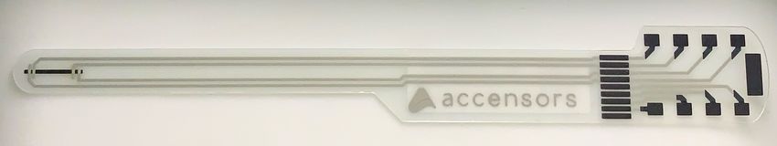
4.1 the sensors
The sensors used are so-called foil sensors, as shown in Figure 4. Their
flexibility and thickness will simplify the integration into a dressing.
A foil sensor is a substrate where conductive elements are applied.
The foil sensor is built in layers that can merge multiple sensors and
form the sensor, making it suitable for the application. When integrat-
ing sensors in wound dressings, it is required that the selected sensor
type is noninvasive, and it must be made of biocompatible materials
to ensure avoidance of creating discomfort for the patient[7]. Temper-
ature and pH will be monitored in the wound, and the sensors are
bought from a German sensor company called Accensors. The com-
pany has several sensors for different types of uses, one of them being
medical. For this reason, these sensors are suitable for this project. To
protect the hardware connected to the dressing, a case will be de-
signed in Fusion 360 and 3D-printed.
Figure 4: The temperature sensor
4.2 temperature measurements
Resistance Temperature Device (RTD) measures temperature through
the change of metal resistance with temperature. The principle be-
hind this is when the temperature of the metal increases, its resis-
tance to the current of electricity increases. The type of metal in the
sensor that is the actual measuring element can vary; however, plat-
inum is the most widely used metal for RTD components. A few of
the platinum’s factors are its correlation between temperature and re-
sistance: linear, stability, and chemical inertness. The RTD elements
can be placed in thin films or in a glass bobbin, depending on their
use. To communicate with the RTD element and get the temperature,
wires are attached and connected to measure. The amount of wires
can vary depending on the sensor. Yet, four wires are used to get
the most accurate measurement. With four wires, it measures the re-
sistance between four different points on the sensor element. This is
done by powering the sensor element between two anodes and two
1314 method and materials
cathodes[30].
The temperature sensor used in this project is an RTD001 with a
platinum-based element, a very flexible and thin model that allows
it to fit almost anywhere without noticing it. The temperature sen-
sor has a response time lower than one second, which is ideal for
real-time monitoring. When measuring temperature in wounds, all
decimals are crucial; with the sensor having an accuracy of +/- 0.2,
the patient would see almost every temperature change. The range
that will be measured is 25°C to 35°C, and the element can measure
between -10°C and 100°C[31].
4.3 ph measurements
A pH sensor can detect the amount of alkalinity and acidity in a va-
riety of solutions. The standard pH scale is usually expressed by a
number that ranges from 0 to 14. A material is called neutral when
it has a pH value of seven. A pH value greater than seven indicates
a higher level of alkalinity, whereas a pH value less than seven indi-
cates that the substance is more acidic. There are different pH sensors
depending on their use, such as combination, process, laboratory, and
differential. The combination pH sensor is the most common sensor
on the market, owing to its ability to serve as the foundation for de-
veloping laboratory and process sensors. This electrochemical sensor
has two electrodes: a reference electrode and a measuring electrode.
The measuring electrode can determine whether there have been any
changes in the pH level, while the reference electrode focuses on keep-
ing the signal constant while recording the pH level[32].
The pH sensor is potentiometric and foil-based and provides a life-
time of 8 hours. The Ion selective electrode is an electrical potential
sensor that converts the action of a particular ion dissolved in a solu-
tion. According to the Nernst equation seen in Equation 1, the volt-
age is proportional to the logarithm of the ionic activity. The refer-
ence electrode is a solid-state electrolyte coated with Ag/AgCl. Solid
electrolytes possess a much higher thermal stability. It also allows
accurate determination of pH in samples regardless of chloride con-
centration. The pH sensor has an accuracy of +/- 0.3 when used less
than 60 minutes; however, it has an accuracy of +/- 0.2 when used
for longer. And knowing the dressing will be on for longer than 60
minutes, the sensor’s accuracy is suitable for this project. It has a
pH range between 5.5-10, which is said to be widened in the second
prototype.
RT
Eise = E0 − ( )ln(ai) (1)
ziF4.4 connection of the temperature sensor 15
4.4 connection of the temperature sensor
The circuit to measure the voltage is shown in Figure 5. The resis-
tor was calculated by Ohms law, as seen in Equation 2. Knowing
the voltage is 3.3 and the current set to 100 microamperes from the
temperature sensor datasheet, the resistance could be calculated to
33 kiloohms. The power source pins on the sensor were connected
to 3.3V on the Arduino board and ground. A resistor of 33k placed
between the sensor and power controls the flow of current to the sen-
sor. There are voltage measurement pins on the sensor placed over
the ground and where the resistor connects to the sensor. To get the
value of the voltage, a wire was connected between an analog pin and
where the resistor and sensor connect.
U = R×I (2)
Figure 5: The circuit for the sensor
4.5 values in arduino ide
To collect data from the temperature sensor, the sensor is connected to
an analog pin. Using the command analogRead(), the measured value
is displayed in the Serial Monitor in the Arduino IDE. A multichannel,
10-bit analog to digital converter is included on Arduino boards. This
means that input voltages between 0 and the operating voltage, 3.3V
in this case, would be translated into integer values between 0 and
1023.
Since the temperature sensor is a variable resistor, the resistance
must be tested before the temperature can be calculated. Although
Arduino can only calculate voltage and not resistance, the voltage
between the sensor and a known resistor will be measured by the Ar-
duino. For this calculation, Equation 3, which is of a voltage divider,16 method and materials
was modified and simplified to get the R2 resistance of the tempera-
ture sensor as resulted in Equation 4.
R2
Vout = Vin( ) (3)
R2 + R1
Vin
R2 = ( + 1) (4)
Vout
When the resistance was measured the Steinhart-Hart formula as
seen Equation 5 is used to convert the resistance of the sensor to a
temperature reading[33]. Where C1, C2 and C3 are given constants
from the data sheet of the temperature sensor.
1
= C1 + C2(lnR2) + C3(lnR2)3 (5)
T
The value is then subtracted by 273.15 to have it presented in Cel-
sius. See Appendix B for the full code.
4.6 wireless transmitting device
Since it was required to have continuous monitoring of the selected
biomarkers, not requiring an active action to retrieve and display data,
wireless transmission via Bluetooth was decided to be used. The Blue-
tooth module HC-05 will be used to connect with the Arduino. In the
Arduino IDE, a library is available, called SoftwareSerial, to include
in the sketch for initializing and accessing the Bluetooth modules.
4.7 development of the smartphone application
The next step is to present the data in a readable way using a smart-
phone application. The first step is to determine for what Operating
System to develop the application for, meaning what smartphone the
application will be compatible with, either iPhone or Android. Due to
the time limitations, the decision was made to proceed with Android
Studios to work with the more familiar programming language Java.
Further investigation also revealed that Android is more compatible
with the Arduino platform, easing the connection process.
To meet the aims of the project following three functions were fo-
cused on:
• Wireless connection with Arduino through Bluetooth
• An indicator to show the status of the wound
• Collect Sensor Data and visually display it4.8 the wound dressing 17
4.7.1 Wireless Connection
The Android platform comprises a Bluetooth API which enables the
application to have a Bluetooth connection. This API has been used
to develop the Bluetooth connecting.[34]. By implementing this API
following functions was enabled:
• Scan for nearby Bluetooth devices
• Find the remote Bluetooth Devices by querying the list of paired
devices
• Create an RFCOMM channel, short for Radiofrequency com-
munication, a Bluetooth protocol working with a simple set of
transport protocols.
• Connect to other devices
• Send and receive data
• It can also manage multiple connections, but this will not be
necessary for this project.
4.7.2 Collection of Data
When the Bluetooth connection is established, the data transfer is en-
abled. To get the application to receive data from the Bluetooth chan-
nel, the subclass Inputstream was used. InputStream is an abstract
class; it is a superclass of classes that handles input streams of bytes.
By connecting the InputStream with the BluetoothSocket, a channel
between the Bluetooth device and Android application is created, and
the application can receive data.
4.7.3 Wound Status Indicator
The idea of the application is to make it easy to understand; the user
must be able to open the application and get a clear view of the sta-
tus of the wound. To increase the clarity in the application, a status
bar was implemented. By designing a status bar with three positions,
green, yellow, red, as images, an image view was used to show each
image depending on the sensor data.
4.8 the wound dressing
An advanced wound care dressing consists of several layers with dif-
ferent functions. The top layer consists of a breathable polyurethane
film called back film, as in Figure 6. The purpose of the back film is to
prevent external bacteria and viruses from entering the wound. The18 method and materials
back film is not waterproof but, to a certain extent water-resistant,
therefore, it is possible to shower with the dressing on. It is an impor-
tant function that the dressing is breathable due to the evaporation
of moisture in the wound bed to prevent maceration. The second
layer in the advanced dressing is a composite layer containing three
different materials. The first material under the back film is a non-
woven spreading layer followed by a super absorbent layer and a
polyurethane foam. Finally, closest to the wound bed is the so-called
Safetac silicone adhesive layer. Adhesive accounts for the stay-on abil-
ity of the dressing. The function of the foam layer is to transport fluids
away from the wound up to the super absorbent layer. The nonwoven
spreading layer distributes and retains fluids to prevent that liquid is
pressed back into the wound bed[35].
A wound dressing needs to have good stay-on abilities and be flexi-
ble. Regarding that this advanced dressing is built in layers, there are
many options for integrating sensors. The temperature sensor needs
to be placed as close to the wound as possible, and the pH sensor
needs to be placed where the dressing absorbs and retains the exu-
date to enable an accurate pH value measurement. The most optimal
placement of the temperature sensor would be between the Safetac
and polyurethane foam layers.
Figure 6: Example of layers in a advanced dressing.4.9 prototype test and evaluation 19 4.9 prototype test and evaluation The functionality of the Android smartphone application will be tested by connecting to the Bluetooth module, and data will be read and transmitted from two separate sensors. The test’s purpose is to see if the Smartphone application can receive and display data and if the Wound status bar responds to changes in an accurate way. The sensors tests will be simulated by using liquids with different pH values and a heating pad for the temperature sensor and not on actual chronic wounds. This would also mean there is no certainty that the simulated tests will reflect reality. The human factor will af- fect the results in consideration of the performance of tests. The rea- soning being that the liquid and heat will manually be applied. The placing of the sensors in the dressing could also be a factor in mea- surement errors. It is essential to have them cover most of the ground dressing for the most accurate monitoring. The main purpose of the testing is to verify that the communication interfaces are functioning.
R E S U LT S
5
A functional conceptual wound monitoring device and data display-
ing Android application has been developed. The device connects
via Bluetooth to the Android Smartphone application. Sensor data
is being transmitted, read and displayed in the applications monitor-
ing screen. Tests show that the Wound Status Bar responds correctly,
meaning, moves to the correct color field based on the input sensor
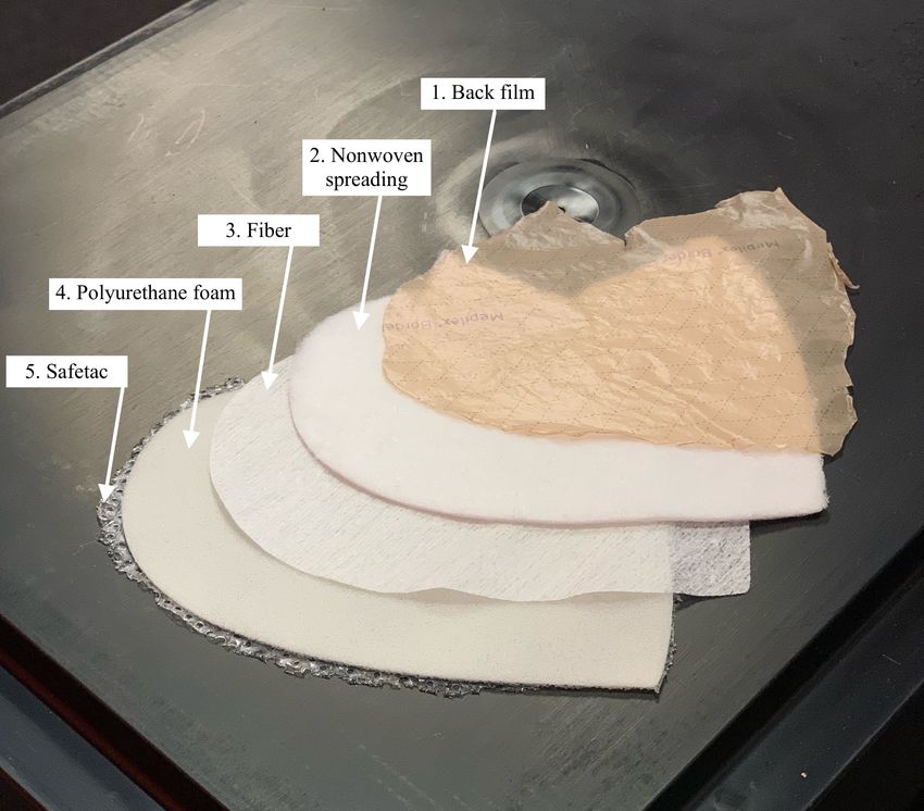
values, see section 5.3. A case protecting hardware has been designed,
and 3D printed, see section 5.2. In Figure 7 and 8 the sensors are in-
tegrated in a multilayered dressing and a wire is connected to the
hardware mounted in its casing is presented. The casing can be kept
in a pocket or clipped on clothes. The first version of an optimized
circuit board has been designed in Figure 9, although it needs further
development to print it out.
Figure 7: The setup of the prototype
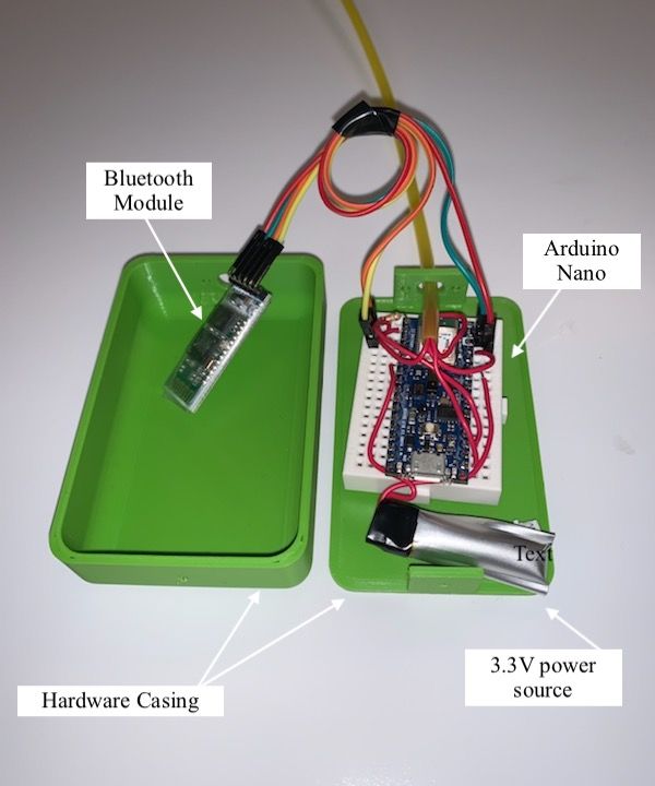
2122 results
Figure 8: The 3D printed case with the electronics
5.1 schematic diagram
The purpose of designing a circuit board is to reduce the form factor.
Only the essential components and pins should be present on this
circuit board. This is for it not to disturb the patient or cause any
unnecessary discomfort. It will be placed in the 3D printed box for
minimal damage. The schematic diagram is made in OrCAD, where
printing it to a circuit board is possible. As seen in Figure 9, the
schematic of the circuit is shown. The pins and components placed
out on this schematic is somewhat different from the original Arduino
Nano since the components that are to no use are not included in the
schematic resulting in fewer pins used.
A USB port is crucial to export the code to the board; it is via the
micro-controller it gets the instructions on how to measure. The re-
set switch is also added for quick fixes when coding the board and
reusing it on other patients. There is an option of using the cryptogra-
phy authentication chip, which will ensure extra security around the
data. When handling patient data, it is always important to guaran-
tee that their values will not be disclosed to anyone if they do not say
otherwise. Instead of having an external Bluetooth module, it will be
an additional component on the board which connects to RX and TX.
The only outer part of the hardware will be the ZiF-connector inte-
grated into the dressing with the sensors, which can also be placed
onto the circuit board for future developments.5.2 hardware casing 23
Figure 9: The schematic diagram for the circuit board
5.2 hardware casing
The finalized hardware casing. Figure 10 presents the CAD-designed
case, and Figure 11 shows the 3D printed hardware casing.
Figure 10: The CAD-version of the hardware casing
Figure 11: The 3D-printed hardware case24 results
5.3 android application
In Figure 12-16, a presentation of the finalized application will be
presented. In the images, there are a number of icons will be used to
explain the functions of the application.
Figure 12: This is the start screen of application.
1. For controlling the local Bluetooth on Smart Phone.
2. Scan button to search for nearby bluetooth devices.5.3 android application 25
Figure 13: This is when the scanning process is done, and nearby Bluetooth
devices are visible. The list is clickable. When the device in the
list is pressed, the next activity will be executed and move on to
the next view.
3. The Bluetooth device nearby the dressing.
Figure 14: This is the monitoring view.
4. Wound status indicator with three different states.
5. Textview component to visually display the sensor data, pH
and Temperature.26 results
Figure 15: 6. Wound Status is on the verge of infection.
Figure 16: 7. Wound Status in an alarming state.DISCUSSION
6
The work has resulted in a functioning conceptual solution for a
wound monitoring dressing even though the results have not fully
reached the planned level of abilities in terms of robust sensor signals
and algorithms for data trending. It requires more investigative work
to develop an electronics solution optimized for the selected sensors
as well as defining strategies for alarm levels and trending algorithms.
The wound care community is still in discussions around accurate
biomarkers to monitor and how to interpret data. Since the high com-
plexity of the area, a large amount of time was spent understanding
the requirements of the sensor connection setup, accuracy, alarm lev-
els, data transmission, and design of a smartphone data management
application. One of the challenges within the project has been to in-
tegrate sensors in a hardware solution and calibrate sensors to get
robust signals. Calibration is done so that the measured value can
be useful; this is done before measuring. The process of it occurs at
a temperature that is known, often in a lab. With other sensors that
work accurately, the initial sensor will read how the output voltage
relates to the reference voltage. The sensor supplier company defined
in the project was relatively newly started and was still developing
sensors for the medical device market. Still, data from sensors were
retrieved, transmitted, and displayed even though final calibration
was not possible to perform.
Due to time constraints development of hardware was not possible,
meaning a circuit board. The Arduino platform was a good tool to
build up the sensor concept since components and software are suf-
ficient for creating and testing a conceptual model. To still develop,
test, and evaluate wireless communication from the electronics de-
vice, handle data signals that could be displayed, and develop the
prototype of a smartphone application, an off-the-shelf temperature
and humidity sensor was used.
Many initiatives and studies are in progress focusing on determin-
ing parameters for detecting infection in chronic wounds, still, no
products are released on the market. No product is released on the
market on account of the uncertainty around chronic wounds and
relevant biomarkers to control. For this reason, it was not possible
to compare the developed solution with others. However, the defined
parameters and alarm levels are well documented in medical research
publications The project has anyway pathed a way forward in defin-
2728 discussion
ing what questions and needs to be solved going forward towards
the next level of wound care monitoring device.
6.1 security
Regarding the security in the android application, the possibility of
an attack hazard is minimal. Since the application only asks permis-
sions to get access to the smartphone Bluetooth and not any personal
data, like location or credit card numbers. The intent used to navigate
in the application is the explicit intent, as mentioned in chapter 3.2 is
the intent that has the lowest risk of being attacked.
In this project, security has not been focused on since the data has
not been sensitive to patient data. It will be an important aspect to
consider for future development, given that patient data must be
highly protected.
6.2 ethics
The patient could feel uncomfortable having their data monitored
and recorded for various reasons, perhaps not knowing who actually
can access this information. The hospitals would need the data to de-
liver the best quality care; the researchers can use it to perform stud-
ies or insurers who believe that they require personal health records
to process claims and pay for treatment adequately. Due to a lack
of trust in the system’s security that holds their data, the patient
can withhold information. However, having their wound status moni-
tored, the data will only be used for what the patient signs up for. The
patients and those who care about their business know personal infor-
mation about them, their bodies, and their health status. Nobody else
would have access to the data until they have given their permission
freely and informedly.CONCLUSION
7
In line with the project scope and aims, a conceptual prototype device
able to measure temperature and pH levels, transmitting measured
values wireless to an Android Smartphone application able to display
data and wound status, were to be developed. The following project
requirements were stated:
• Decide biological parameter to measure
• Enable wireless data transmission
• Enable live monitoring of selected parameters
The first requirement was to decide the biomarkers to be measured
together with applicable biosensors. The initial research resulted in
the selection of temperature and pH to be the monitored biomark-
ers. The second and third requirements solution were combined in
developing an android application receiving data via Bluetooth. The
application itself had the following requirements:
• Wireless connection with Arduino through Bluetooth
• An indicator to show the status of the wound
• Collect sensor data and visually display it
The requirements of the Android application were all fulfilled. Even
though the biosensors were not fully calibrated and able to measure
as accurately as intended, the process of selecting the biosensor and
understand the measurement techniques were highly educative. The
project gave insights into sensor functionality and the importance of
understanding the sensor characteristics and their impact on perfor-
mance. The project also brought knowledge in the programming of
applications for smartphones and wireless connectivity technologies.
7.1 future development
It still exists inconsistencies around treatment protocols for chronic
wound care. The lack of standardization often creates inefficient care.
Digitalization of health care, and in this case, chronic wound manage-
ment, is an excellent opportunity in chronic wound research to col-
lect data from a Smart Dressing to build knowledge in therapies and
treatments by developing decision algorithms using Big Data man-
agement and data mining strategies and by this create a foundation
2930 conclusion
for standardization of chronic wound care.
There are many ongoing initiatives, but still, no product is released
on the market. There still exists a large uncertainty and complexity
around chronic wounds and relevant biomarkers and interpretation
of measured values. Therefore, a chronic wound monitoring wear-
able would be vital for further research on wound healing and corre-
lated biomarkers by collecting a large amount of data and using data
mining principles to find patterns and parameters impacting chronic
wound healing.
To reduce complexity for users that might not have or can handle
smartphones, instead of using an android application as the commu-
nication system, an alternative solution could be connected to the
sensors as a wound status indicator. For some examples, integrating
LEDs in a bracelet or a patch attachable to clothes can indicate the
wound’s status. This means all the components such as sensors, mi-
crocontroller, and Bluetooth module is required; it is only the display-
ing device that is exchanged.
To make the Smart Dressing even more convenient, the option of
adding a ZiF-connector component straight onto the circuit board
will remove the trouble of having a wire to manage. The idea of hav-
ing it in a concealed casing would still be available; however, since it
will only be the ZiF-connector that is connected to the Smart Dress-
ing, the patient can detach it when showering and sleeping including
reattaching it when done. Although it is not seen as a significant is-
sue since the wire can easily be disclosed, the patient would feel more
comfortable without it.BIBLIOGRAPHY
[1] Patrick Lin. “Chapter 2 - From wearables to implantables—clinical
drive and technical challenges.” In: (2020), p. 660.
[2] Glucose monitor now available on the NHS is diabetes ‘game changer’.
Accessed: 2021-01-28.
[3] How medical engineering has changed our understanding of chronic
wounds and future prospectsDowload Xcode. Accessed: 2021-04-01.
[4] The quality of life of people who have chronic wounds and who self-
treat. Accessed: 2021-01-26.
[5] How Digitizing Wound Care Empowers Clinicians and Engages Pa-
tients. Accessed: 2021-04-01.
[6] Wearable Technology for Chronic Wound Monitoring: Current Dress-
ings, Advancements, and Future Prospects. Accessed: 2021-01-27.
[7] A flexible and low power telemetric sensing and monitoring system
for chronic wound diagnostics. https://biomedical-engineering-
online.biomedcentral.com/articles/10.1186/s12938- 015-
0011-y. Accessed: 2021-01-27.
[8] Human Wounds and Its Burden: An Updated Compendium of Esti-
mates. Accessed: 2021-01-28.
[9] How Digitizing Wound Care Empowers Clinicians and Engages Pa-
tients. Accessed: 2021-03-01.
[10] Introduction to biosensors. Accessed: 2021-03-04.
[11] Bin LIU and Ben Zhong TANG. “Biosensors.” In: Macromolecu-
lar rapid communications. 34.9 (2013). issn: 1022-1336.
[12] Effectiveness of biofilm-based wound care system on wound healing
in chronic wounds. Accessed: 2021-01-27.
[13] Alessandro D’Ausilio and Alessandro D’Ausilio. “Arduino: A
low-cost multipurpose lab equipment.” In: Behavior research meth-
ods 44.2 (2012), pp. 305–313. issn: 1554-3528.
[14] Gehlot Anita. Singh Rajesh. Singh Bhupendra. Choudhury Sushab-
han. In: Macromolecular rapid communications. (2018).
[15] Wireless and Mobile Technologies for the Internet of Things. Accessed:
2021-03-01.
[16] Bluetooth LE Finds Its Niche. Accessed: 2021-03-01.
[17] The Survey on Near Field Communication. https : / / www . mdpi .
com/1424-8220/15/6/13348/htm. Accessed: 2021-03-01.
3132 bibliography
[18] Comparative analysis of Android and iOS from security viewpoint.
https : / / www - sciencedirect - com . ezproxy . bib . hh . se /
science/article/pii/S1574013721000125. Accessed: 2021-04-
01.
[19] Android Definition. https://techterms.com/definition/android.
Accessed: 2021-04-01.
[20] Kernel Definition. https://techterms.com/definition/kernel.
Accessed: 2021-04-01.
[21] Dowload Android Studios. https : / / developer . android . com /
studio?gclid=Cj0KCQiA1pyCBhCtARIsAHaY_5e-xFojsCyXplqLbySdb14y5F7IM-
SdV4I_j1thgL8SuO7p6IUHAPEaAtyeEALw_wcB&gclsrc=aw.dsDownload
Android Studios. Accessed: 2021-03-09.
[22] Dowload Xcode. https : / / developer . apple . com / xcode/. Ac-
cessed: 2021-03-09.
[23] Fusion 360. https : / / www . autodesk . se / products / fusion -
360/subscribe?plc=F360&term=1- YEAR&support=ADVANCED&
quantity=1. Accessed: 2021-04-01.
[24] OrCAD Download. https://www.orcad.com/resources/orcad-
downloads. Accessed: 2021-04-01.
[25] pH-responsive materials for optical monitoring of wound status. https:
//www.sciencedirect.com/science/article/pii/S0925400519311657.
Accessed: 2021-01-28.
[26] Permission based Android security: Issues and countermeasures. https:
/ / www - sciencedirect - com . ezproxy . bib . hh . se / science /
article/pii/S0167404814000261. Accessed: 2021-04-01.
[27] APSET, an Android aPplication SEcurity Testing tool for detecting
intent-based vulnerabilities. https://link-springer-com.ezproxy.
bib.hh.se/article/10.1007/s10009- 014- 0303- 8. Accessed:
2021-04-01.
[28] Intents and Intent Filters. https : / / developer . android . com /
guide/components/intents-filters. Accessed: 2021-04-01.
[29] Permissions on Android. https : / / developer . android . com /
guide/topics/permissions/overview. Accessed: 2021-04-01.
[30] Application of RTD Sensor in the Real Time Measurement and Wire-
less Transmission. https : / / ieeexplore . ieee . org / abstract /
document/6995110?casa_token=-wy_Ze4iDDwAAAAA:WiMIozKQgW4Jhd8CzUDp2ExQWuq
FR-pOV-aqAMK6-xCrKO. Accessed: 2021-04-01.
[31] Datasheet Temperature. https : / / accensors . com / wp - content /
uploads/2020/04/accensors_Datasheet_Temperature_RTD001Pt70-
PET200-IDP322B20_V0.4.pdf. Accessed: 2021-03-04.
[32] A Solid-State Thin-Film Ag/AgCl Reference Electrode Coated with
Graphene Oxide and Its Use in a pH Sensor. Accessed: 2021-04-05.bibliography 33
[33] Temperature Measurement in Dimensional Metrology – Why the Steinhart-
Hart Equation works so well. https : / / www . kalorimetrietage .
ptb.de/fileadmin/documents/macroscale/proceedings/2011/
8_2011_Matus__M.pdf. Accessed: 2021-03-03.
[34] Bluetooth overview. https : / / developer . android . com / guide /
topics/connectivity/bluetooth. Accessed: 2021-03-05.
[35] Produkter med Safetac teknologi. https://ipaper.ipapercms.dk/
Molnlycke / se / Wound / produktkatalog - saar - 2013 / ?page = 24.
Accessed: 2021-03-03.ANDROID CODE
A
Figure 17: Psuedo code Application, the MainActivity.class
3536 bibliography
Figure 18: Psuedo code Application (part 1), the Monitor.class
Figure 19: Psuedo code Application (part 2), the Monitor.classARDUINO CODE
B
Figure 20: The code in the Arduino IDE
37Julia Anderberg, Alina Uddin, PO Box 823, SE-301 18 Halmstad Phone: +35 46 16 71 00 E-mail: registrator@hh.se www.hh.se
You can also read