Biffi ICON3000 Modbus RTU Module - Biffi Actuators
←
→
Page content transcription
If your browser does not render page correctly, please read the page content below
Installation, Operation and Maintenance Manual
                                                                                                                                                                         MDE 250 Rev. 7
                                                                                                                                                                           March 2021

Biffi ICON3000
Modbus RTU Module

Copyright © Biffi. The information in this document is subject to change without notice. Updated data sheets can be obtained from our website www.biffi.it or from your nearest Biffi Center:
Biffi Italia s.r.l. - Strada Biffi 165, 29017 Fiorenzuola d'Arda (PC) – Italy PH: +39 0523 944 411 – biffi_italia@biffi.it
Revision Details                                       Installation, Operation and Maintenance Manual
March 2021                                                                                    MDE 250 Rev. 7

Revision Details

 Rev.        Date                       Description                   Prepared      Checked     Approved
  7       March 2021     General update (Migration to new template)
  6        May 2019                    Seventh Issue                  L. Piacenti                C. Doglio
  5      October 2018                   Sixth Issue                   L. Piacenti               A. Battaglia
  4       April 2018                     Fifth Issue                  L. Piacenti               A. Battaglia
  3      February 2018                  Fourth Issue                  L. Piacenti               A. Battaglia
  2      February 2018                  Third Issue                   L. Piacenti               A. Battaglia
  1      February 2018                 Second Issue                   L. Piacenti               A. Battaglia
  0      January 2018                    First Issue                  L. Piacenti               A. Battaglia

                                                                                                Revision Details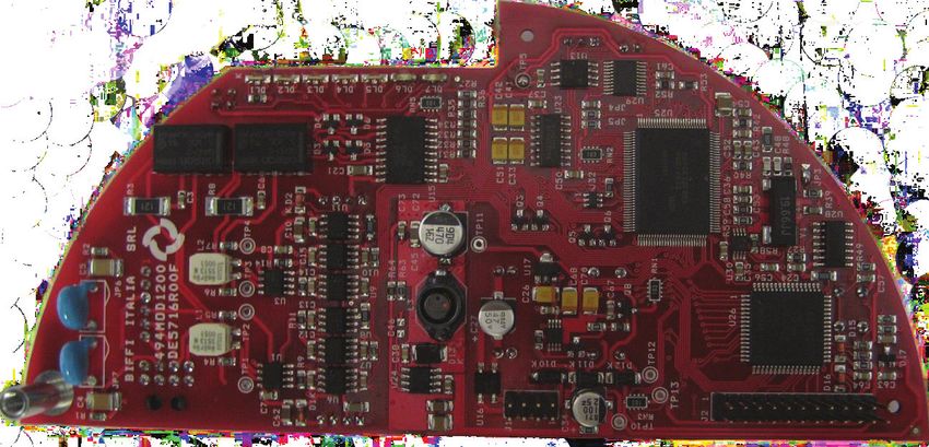
Installation, Operation and Maintenance Manual                                                                        Table of Contents
MDE 250 Rev. 7                                                                                                                       March 2021

Table of Contents
                    Section 1:      Introduction
                          1.1     References..................................................................................................... 1
                          1.2     Modbus RTU or ASCII..................................................................................... 1

                    Section 2:      Operation and Storage
                          Operation and Storage..............................................................................................2

                    Section 3:      Communication Features
                          Communication Features..........................................................................................3

                    Section 4:      Modbus RTU Module
                          4.1     On Board Indications and Jumpers.................................................................. 5

                    Section 5:      Modbus RTU Protocol Description
                          Modbus RTU Protocol Description............................................................................6

                    Section 6:      Modbus Wirings
                          6.1     RS485 Transmission Mode............................................................................. 7

                    Section 7:      Modbus I/O List
                          7.1     Discrete Inputs............................................................................................. 10
                          7.2     Coils............................................................................................................. 11
                          7.3     Analog Inputs............................................................................................... 13
                          7.4     Holding Registers......................................................................................... 20

                    Section 8:      Modbus Function Description
                          8.1  Function Code 01 (0x01) Read Coils Status................................................... 34
                          8.2  Function Code 16 (0x10) Write Multiple Registers....................................... 35
                          8.3  Function Code 03 (0x03) Read Holding Registers......................................... 36
                          8.4  Function Code 04 (0x04) Read Input Registers............................................. 37
                          8.5  Function Code 05 (0x05) Write Single Coil................................................... 38
                          8.6  Function Code 06 (0x06) Write Single Register............................................. 39
                          8.7  Function Code 08 (0x08) Diagnostic............................................................ 40
                               8.7.1 Sub-Function 00 (0x0000) Return Query Data................................... 40
                               8.7.2 Sub-Function 11 (0x000B) Return Bus Message Count....................... 40
                               8.7.3 Sub-Function 12 (0x000C) Return Bus Communication Error Count.. 40
                               8.7.4 Sub-Function 13 (0x000D) Return Bus Exception Error Count............ 41
                               8.7.5 Sub-Function 14 (0x000E) Return Slave Message Count.................... 41
                               8.7.6 Sub-Function 17 (0x0011) Return Slave Busy Count.......................... 41
                               8.7.7 Sub-Function 18 (0x0012) Return Bus Character Overrun Count....... 41
                          8.8 Function Code 15 (0x0F) Write Multiple Coils............................................... 42
                          8.9 Function Code 16 (0x10) Write Multiple Registers........................................ 43
                          8.10 Function Code 17 (0x11) Report Slave ID...................................................... 44
                          8.11 Exception Codes........................................................................................... 45

Table of Contents                                                                                                                                         i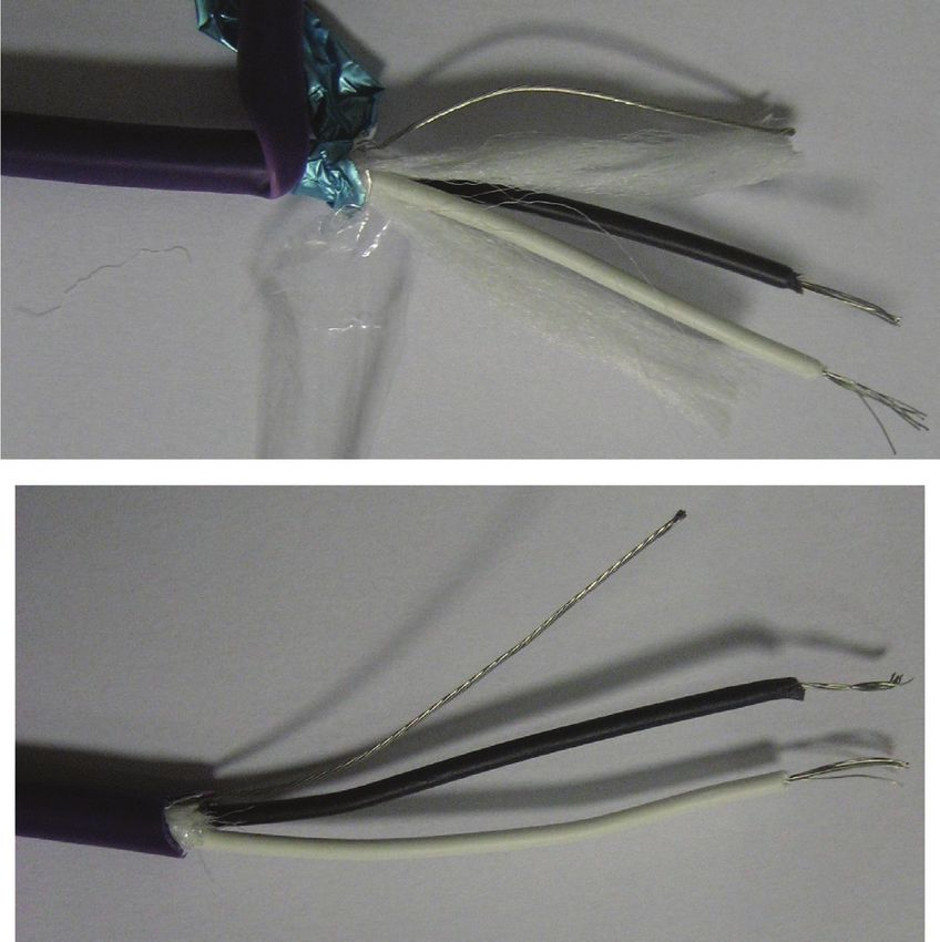
Table of Contents                                 Installation, Operation and Maintenance Manual
March 2021                                                                                                           MDE 250 Rev. 7

             Section 9:      Configuration via Local Interface of ICON3000
                    9.1    BUS Control.................................................................................................. 46
                    9.2    Positioner Function...................................................................................... 48
                    9.3    Fail Safe Function......................................................................................... 49
                    9.4    Viewing Transmission Info............................................................................ 50
                    9.5    BUS Signal Failure Indication........................................................................ 50
                    9.6    Actuator Terminal Board.............................................................................. 51

             Section 10: Annex A
                    10.1 Replacement of 494MOD1000 with 494MOD1200...................................... 52

             Section 11: Annex B
                    11.1 Multiple Functionality of ESD Command and Status..................................... 54

ii                                                                                                                      Table of Contents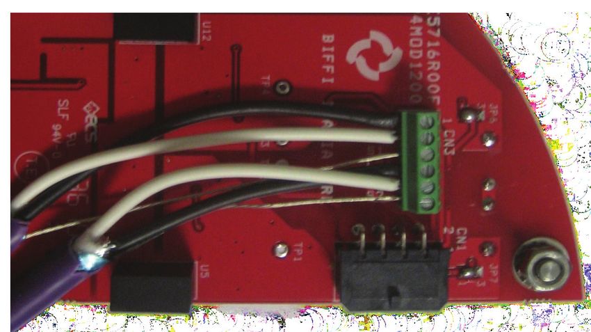
Installation, Operation and Maintenance Manual                                          Section 1: Introduction
MDE 250 Rev. 7                                                                                              March 2021

Section 1: Introduction
                 The ICON3000 Modbus RTU is an electronic module that allows connecting the Biffi electrical
                 actuator ICON3000 to a Modbus RTU serial communication line. The module has its microprocessor,
                 it is controlled by a program stored internally, it works as a pure BUS interface and does not affect the
                 actuator control integrity. It is installed inside the actuator housing and takes the electrical power
                 from the actuator power supply module. The RS485 interface is located on the module board.
                 The data lines are fully isolated from the actuator electronics.
                 All features described in this document are applicable for software revision 2.01 or subsequently.
                 ICON3000 Modbus RTU module can be mounted only on base card revision 9.00 or higher.

1.1              References
                 Modbus over serial line specification and implementation guide V1.02.
                 Available from www.modbus.org.
                 Modbus application protocol specification V1.1b3. Available from www.modbus.org.
                 ICON3000 Installation, Operation and Maintenance Manual, VCIOM-14675-EN.

1.2              Modbus RTU or ASCII
                 Modbus protocol is currently supported by most Programmable Logic Controllers (PLCs).
                 Modbus is a very simple Master/Slave serial protocol. It supports both ASCII (rarely used) and
                 Binary (RTU) form of transmission. In ASCII transmission mode each 8-bit byte in a message is sent
                 as 2 ASCII characters. In RTU transmission mode each 8-bit byte is sent as 2 four-bit hexadecimal
                 characters. The main advantage of RTU mode is that it allows greater character density than in ASCII
                 mode at the same baud rate.
                 The structure of a Modbus message is shown below.

                          Address                  Function                     Data                   Checksum

Introduction                                                                                                             1
Section 2: Operation and Storage             Installation, Operation and Maintenance Manual
March 2021                                                                                     MDE 250 Rev. 7

Section 2: Operation and Storage
              The module is designed to work and to be stored in the same environment of the actuator.

2                                                                                           Operation and Storage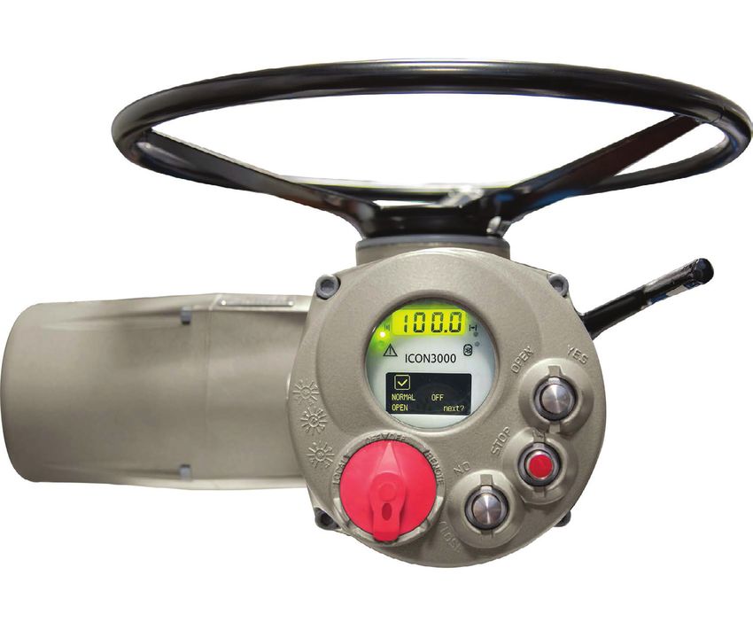
Installation, Operation and Maintenance Manual Section 3: Communication Features
MDE 250 Rev. 7                                                                                         March 2021

Section 3: Communication Features
                    Communication Protocol:    Modbus RTU
                    Transmission Technology:   RS485, half duplex
                    Network Topology:		        Line (BUS) structure
                    Transmission Medium:		     Twisted, screened copper cable
                    Data Rate:			              600, 1200, 2400, 4800, 9600, 19200, 38400 bit/s
                    Device Number:             Maximum 32 devices per segment. If more than 32 devices are
                    				                       present on the BUS, repeaters should be used
                    Slave Address:			          From 1 to 247 (address 0 reserved for broadcast messages),
                    				                       configurable via local operator interface of actuator
                    BUS Access:			             Polling between masters and slaves
                    Electrical Power:		        Actuator powered
                    BUS Termination:		 Available on board, configurable via local operator
                    				interface of actuator
                    Temperature:   		          -40 °C, +85 °C
                    Fieldbus Redundancy:		     Available by setting the MODE function (CH1, CH2, AUTO)
                    Auto Baud Rate:            Available by setting “Baud Rate = AUTO”
                    EMC Protections:		         EN 50081-2 and EN 50082-2
                    Baud Rate:			              Configurable via local operator interface of actuator
                    Addressing:			             Configurable via local operator interface of actuator
                    Coding System:		           8 bits binary, hexadecimal 0-9, A-F. Two hexadecimal
                    				                       characters contained in each 8-bit field of the message
                    Bits per byte:			          1 start bit
                    		                		       8 data bits, least significant bit sent first
                    		 		                      1 bit for Even/Odd parity; no bit for no parity; configurable
                    				                       via local operator interface of actuator
                    		                		       1 stop bit with parity; 2 Stop bits without parity
                    Error Check Field:		       Cyclical Redundancy Check (CRC)

Communication Features                                                                                          3
Section 4: Modbus RTU Module Installation, Operation and Maintenance Manual
March 2021 MDE 250 Rev. 7
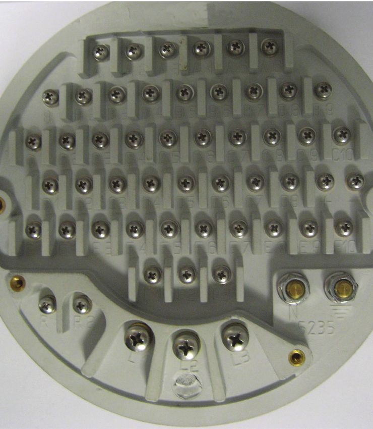
Section 4: Modbus RTU Module
The module consists in a single PCB that is installed inside the actuator housing. It is connected to the
ICON3000 base card via strip connector.
The internal wiring connects the RS485 data lines to the actuator terminal board.
Figure 1 Top Side
Figure 2 Bottom Side
4 Modbus RTU Module
Installation, Operation and Maintenance Manual                              Section 4: Modbus RTU Module
MDE 250 Rev. 7                                                                                             March 2021

4.1                 On Board Indications and Jumpers
                    Seven LEDs are mounted on the Modbus RTU module to give the following indications for the field
                    service. LEDs indicators are active only when jumper JP1 is closed.
                    DL1 (green) Power Supply: 		                ON: When the Modbus RTU module is correctly
                    					                                       powered from the main power supply
                    					                                       OFF: When the Modbus RTU module is not correctly
                    					                                       powered from the power supply
                    DL2 (green) CH1 Comm. Status:		             ON: Data Message received or transmit from
                    					Modbus RTU interface
                    					                                       OFF: Silence between Data Modbus messages
                    					                                       BLINK: Auto Baud Rate Running
                    DL3 (green) CH2 Comm. Status:		             ON: Data Message received or transmit from
                    					Modbus RTU interface
                    					                                       OFF: Silence between Data Modbus messages
                    					                                       BLINK: Auto Baud Rate Running
                    DL4 (green) Termination CH1:		              ON: Termination Resistance Active on CH1
                    					                                       OFF: Termination Resistance Not Active on CH1
                    DL5 (green) Termination CH2:		              ON: Termination Resistance Active on CH2
                    					                                       OFF: Termination Resistance Not Active on CH2
                    DL6 (red) Base Card Comm. Status:           ON: Communication Errors
                         		                                     OFF: Not Communication Errors
                    DL7 (red) Data Area Empty:		                ON: When Data Area on interface card is not yet loaded
                    					                                       OFF: When Data Area is completely loaded
                         		                                     BLINK: When Data Area is being read from base card
                    JP1: LEDs jumper. Short this jumper to power LEDs (default OFF).
                    JP2: Program jumper. Used to download new firmware on microcontroller (manufacturer use only).

Modbus RTU Module                                                                                                        5
Section 5: Modbus RTU Protocol Installation, Operation and Maintenance Manual
March 2021 MDE 250 Rev. 7
Section 5: Modbus RTU Protocol Description
Modbus protocol is a messaging structure, used in a wide range of application in process automation
to establish master-slave communication between intelligent devices. Since Modbus is only a
messaging structure, it is independent from the physical layer. It is traditionally implemented using
RS232 or RS422 or RS485. The central controllers (as PLC) communicate via serial connection
with field devices (as sensors, actuators). The central controller (called master) reads the input
information from the field devices (called slaves) and writes the output information to the slaves.
The master initiates the transmission which is called “query.” The slave devices answer by sending the
requested data (called “response”) and performing the action requested in the query. The master can
address individual slaves or can send a broadcast message to all slaves.
The figure below shows a query-response cycle.
Figure 3
Address Function Data Checksum
query
response
Address Function Data Checksum
No response from slaves is done in case of broadcast message. Address 0 is used for the
broadcast message.
If a slave receives the request, but detects a communication error (parity, CRC, etc.) no response
is returned.
If a slave receives the request without a communication error, but cannot handle it (for example,
if the request is to read a non-existent output or register), the slave will return an exception response
informing the master of the nature of error.
6 Modbus RTU ProtocolInstallation, Operation and Maintenance Manual Section 6: Modbus Wirings
MDE 250 Rev. 7 March 2021
Section 6: Modbus Wirings
The maximum number of master and slave devices in a BUS segment is 32 without repeaters.
The maximum cable length depends on the speed of transmission. Higher is the speed shorter should
be the cable length.
The figure below shows a Modbus RTU configuration with 1 master device and different slave devices.
Figure 4
PLC Master Device
General I/O Transmitter
Slave Devices
Actuator Actuator
6.1 RS485 Transmission Mode
The ICON3000 Modbus RTU module uses a half-duplex, multidrop, serial communication line RS485.
The module communicates with the masters via RS485 interface and the transmission media consists
in a shielded twisted pair cable. Transmission speed from 600 bit/s to 38400 bit/s is available.
One unique transmission speed is allowed for all devices on the BUS when the system works.
All devices are connected in a BUS structure. Up to 32 stations (master and slaves) can be connected
in one segment. Repeaters should be used to extend the number of devices on one BUS.
Addresses range is from 1 to 247. Address 0 is reserved for broadcast messages.
The BUS must be terminated by a resistor of 120 Ω at the beginning and at the end of each segment.
Only two terminations in one BUS segment must be provided. To ensure error-free operation and to
increase driving capability, pull-up and pull-down resistors should be provided on the termination
network. The maximum cable length depends on the transmission speed.
The data lines must not be reversed. To avoid polarity inversion, it is suggested to use different
colours for each data line. Use of shielded cable is mandatory for having high system immunity
against electromagnetic distFurbs. The data lines should be kept separate from all other cables.
It should be laid in separate, conductive and earthed cable trunking. It must be ensured that there is
no voltage difference between individual nodes of BUS.
Modbus Wirings 7Section 6: Modbus Wirings Installation, Operation and Maintenance Manual
March 2021 MDE 250 Rev. 7
Figure 5
Device 1 Device 2
RxD/TxD-P Data Line
RxD/TxD-P
RxD/TxD-N RxD/TxD-N
Data Line 120 Ω
shielding
BUS
Cable
Termination
Ground Ground
The ICON3000 Modbus RTU module takes its electrical supply from the actuator power supply
module. The RS485 BUS transceiver is isolated from the actuator electronics. The BUS termination,
located inside the actuator, should be used only if the actuator is at the beginning or at the end of the
BUS segment and if there is no external termination.
The BUS terminations can be switched on the data lines by means of 2 links, configurable via local
operator interface.
The figure below shows the wiring in case of single BUS cable.
Figure 6
Terminal Board
ICON3000 Modbus RTU
VP
Module
47 KΩ Rx/Tx-P-in
Data Line
Rx/Tx-P-out
RS485 Termination
control 120 Ω
transceiver Rx/Tx-N-in
Data Line
Rx/Tx-N-out
47 KΩ Ground
DGND
Ground
8 Modbus WiringsInstallation, Operation and Maintenance Manual Section 6: Modbus Wirings
MDE 250 Rev. 7 March 2021
The figure below shows the BUS with an actuator at the end of the BUS segment.
Figure 7
PLC
MAINS MAINS MAINS
Termination No No Termination
on data line Termination Termination on data line
BUS cable
The ICON3000 Modbus RTU module is provided with 2 RS485 transceivers and 2 BUS terminations for
application with redundant cable. The BUS terminations can be switched on the data lines by means
of 2 links, configurable via local operator interface. One channel at time works, according to the
configuration received from BUS or via local operator interface. The figure below shows the wiring
necessary in case of redundant BUS cable. The termination must be linked to the data lines only if the
actuator is at the beginning or at the end of the BUS segment.
Figure 8
BUS in BUS out
VP1 47 KΩ RxD/TxD-P
Data line
ICON3000_MOD_TRU
Termination Channel 1
120 Ω
control 1
RxD/TxD-N
Data line
DGND1 47 KΩ Ground
Ground
VP2 47 KΩ
Data line
RxD/TxD-P
Termination 120 Ω Channel 2
control 2
RxD/TxD-N
Data line
DGND2 47 KΩ
Terminal
board
Modbus Wirings 9Section 7: Modbus I/O List Installation, Operation and Maintenance Manual
March 2021 MDE 250 Rev. 7
Section 7: Modbus I/O List
The following paragraph describes the I/O composition of the Modbus interface implemented
in the ICON3000 Modbus RTU module. The ICON3000 Modbus RTU module concentrates all the
available data in the Holding Register Data Area, but to grant the backward compatibility with the
ICON2000v4, it maintains also the former data structure.
The Modus interface is divided in four areas and each area is accessible via the specific Modbus
Function Code as described in Section 8.
7.1 Discrete Inputs
In the Discrete Input Data Area, the ICON3000 Modbus RTU module implements the same 32
discrete inputs available on ICON2000v4.
Status of discrete inputs is indicated as 1 = ON and 0 = OFF.
The following table shows the discrete inputs implemented in the ICON3000 Modbus RTU module:
Table 1.
ICON2000v4 legacy data block
Input Status Number Input Status Address Description
1 0 Close Limit
2 1 Open Limit
3 2 Actuator Moving
4 3 Monitor Relay
5 4 Selector in LOCAL
6 5 Selector in REMOTE
7 6 Alarm
8 7 Warning
9 8 DIN1 (See Note 1)
10 9 DIN2 (See Note 1)
11 10 DIN3 (See Note 1)
12 11 DIN4 (See Note 1)
13 12 DIN5 (See Note 1)
14 13 DIN6 (See Note 1)
15 14 Interlock Open
16 15 Interlock Close
17 16 Fail Safe Action
18 17 Actuator Opening
19 18 Actuator Closing
20 19 Selector in OFF
21 20 ESD/PST Control (see Section 11.1 for details)
22 21 Hardwired Remote Mode
23 22 Positioner Mode
24 23 Motor Operation Inhibited
25 24 Channel 1 Active
26 25 Hardwired Open Command
27 26 Hardwired Close Command
28 27 Hardwired Stop Command
29 28 Hardwired BUS-on
30 29 Base Card Communication Error (Reserved)
31 30 Reserved (always 0)
32 31 Reserved (always 0)
10 Modbus I/O ListInstallation, Operation and Maintenance Manual Section 7: Modbus I/O List
MDE 250 Rev. 7 March 2021
NOTE:
DIN1, DIN2, DIN3, DIN4, DIN5, and DIN6:
Via local operator interface of the actuator, the bits DIN1, DIN2, DIN3, DIN4, DIN5, and DIN6 can
be individually configured to be set to “1” if one of the following condition occurs: open limit, close
limit, position >= xx%, positionSection 7: Modbus I/O List Installation, Operation and Maintenance Manual
March 2021 MDE 250 Rev. 7
NOTE:
1. Open Command, Close Command, Stop Command:
“Open” and “Close” commands are self-maintained.
If “Open command” is active and “Close command” is received, the movement is reversed and
“Open command” is cleared.
If “Close command” is active “Open command” is received, the movement is reversed and
“Close command” is cleared.
If “Stop Command” is received, “Open command” and “Close command” will be ignored.
When “Stop Command” return to 0, “Open command” and “Close command” can be carried out.
To clear “Open command” it’s necessary to set “Stop Command” to ON and to set “Open command”
to OFF.
To clear “Close command” it’s necessary to set “Stop Command” to ON and to set “Close command”
to OFF.
2. Open, Close, Stop, ESD, Positioner mode:
“Local Stop pressed,” “Selector in OFF,” “Selector in REMOTE” stops temporarily all commands;
when the local STOP is depressed, or the selector returns in REMOTE position, the previous command
is restored.
3. ESD/PST Command:
If the value is ON, an ESD/PST command is generated. When the signal returns to OFF, the ESD/PST
command is cleared. See Section 11.1 for details.
4. Positioner Mode:
“Positioner Mode” command is available only in modulating actuators.
If its value is ON, the positioner function is enabled, and the actuator will position according to the
content of position request register (Holding Register address 1).
12 Modbus I/O ListInstallation, Operation and Maintenance Manual Section 7: Modbus I/O List
MDE 250 Rev. 7 March 2021
7.3 Analog Inputs
In the Analog Input Data Area, the ICON3000 Modbus RTU module implements the same 369 input
registers available on ICON2000v4.
The following table shows the input registers implemented in the ICON3000 Modbus RTU module:
Table 3.
ICON2000v4 legacy data block
Input Register Input Register
Range Value Description
Number Address
1 0 0 - 1000 Actuator Position (0=0.0%, 1000=100.0%)
2 1 -100 - 100 Output Torque (See Note 1)
3 2 0 - 65535 Warnings (See Note 2)
4 3 0 - 65535 Alarms1 (See Note 3)
5 4 0 - 65535 Alarms2 (See Note 4)
6 5 0 - 65535 Opening Time (s)
7 6 0 - 65535 Closing Time (s)
8 7 0 - 65535 Contactor Cycles (1/2) (See Note 5)
9 8 0 - 65535 Contactor Cycles (2/2) (See Note 5)
10 9 0 - 65535 Motor Run Time (1/2) (See Note 6)
11 10 0 - 65535 Motor Run Time (2/2) (See Note 6)
12 11 0 - 65535 Time without electrical power (1/2) (See Note 6)
13 12 0 - 65535 Time without electrical power (2/2) (See Note 6)
14 13 0 - 100 Reserved - Util. Rate (0=0%, 100=100%)
15 14 - Test Date (1/2) (See Note 7)
16 15 - Test Date (2/2) (See Note 7)
17 16 - Recent Log Date (1/2) (See Note 7)
18 17 - Recent Log Date (2/2) (See Note 7)
19 18 0 - 65535 Recent Contactor Cycles (1/2) (See Note 5)
20 19 0 - 65535 Recent Contactor Cycles (2/2) (See Note 5)
21 20 0 - 65535 Recent Motor Run Time (1/2) (See Note 6)
22 21 0 - 65535 Recent Motor Run Time (2/2) (See Note 6)
23 22 0 - 65535 Recent time without electrical power (1/2) (See Note 6)
24 23 0 - 65535 Recent time without electrical power (2/2) (See Note 6)
25 24 0 - 100 Reserved - Recent Util. Rate (0=0%, 100=100%)
26 25 0 - 65535 Torque profile in OP - Break Out
27 26 0 - 65535 Torque profile in OP - Peak
28 27 0 - 65535 Torque profile in OP - Ending
29 28 - Date of last torque profile in OP (1/2) (See Note 7)
30 29 - Date of last torque profile in OP (2/2) (See Note 7)
31 30 0 - 65535 Torque profile in CL - Break Out
32 31 0 - 65535 Torque profile in CL - Peak
33 32 0 - 65535 Torque profile in CL - Ending
Modbus I/O List 13Section 7: Modbus I/O List Installation, Operation and Maintenance Manual
March 2021 MDE 250 Rev. 7
ICON2000v4 legacy data block
Input Register Input Register
Range Value Description
Number Address
34 33 - Date of last torque profile in CL (1/2) (See Note 7)
35 34 - Date of last torque profile in CL (2/2) (See Note 7)
36 35 0 - 65535 Torque reference in OP - Break Out
37 36 0 - 65535 Torque reference in OP - Peak
38 37 0 - 65535 Torque reference in OP - Ending
39 38 - Date of torque reference in OP (1/2) (See Note 7)
40 39 - Date of torque reference in OP (2/2) (See Note 7)
41 40 0 - 65535 Torque reference in CL - Break Out
42 41 0 - 65535 Torque reference in CL - Peak
43 42 0 - 65535 Torque reference in CL - Ending
44 43 - Date of torque reference in CL (1/2) (See Note 7)
45 44 - Date of torque reference in CL (2/2) (See Note 7)
46-47-48-49-50 45-46-47-48-49 - Alarms1 Code, date, time (See Note 8)
51-52-53-54-55 50-51-52-53-54 - Alarms2 Code, date, time (See Note 8)
56-57-58-59-60 55-56-57-58-59 - Alarms3 Code, date, time (See Note 8)
61-62-63-64-65 60-61-62-63-64 - Alarms4 Code, date, time (See Note 8)
66-67-68-69-70 65-66-67-68-69 - Alarms5 Code, date, time (See Note 8)
71-72-73-74-75 70-71-72-73-74 - Warning1 Code, date, time (See Note 9)
76-77-78-79-80 75-76-77-78-79 - Warning2 Code, date, time (See Note 9)
81-82-83-84-85 80-81-82-83-84 - Warning3 Code, date, time (See Note 9)
86-87-88-89-90 85-86-87-88-89 - Warning4 Code, date, time (See Note 9)
91-92-93-94-95 90-91-92-93-94 - Warning5 Code, date, time(See Note 9)
96 95 - Nominal Torque/Thrust (1/4) (See Note 10)
97 96 - Nominal Torque/Thrust (2/4) (See Note 10)
98 97 - Nominal Torque/Thrust (3/4) (See Note 10)
99 98 - Nominal Torque/Thrust (4/4) (See Note 10)
100 99 -127 - 127 Min. temperature of base card (°C)
101 100 -127 - 127 Max. temperature of base card (°C)
102 101 -127 - 127 Min. temperature of terminal board (°C)
103 102 -127 - 127 Max. temperature of terminal board (°C)
104 103 -127 - 127 Max. temperature of motor (°C)
105 104 0 - 65535 Number of motor alarm
106 105 0 - 65535 Number of torque alarm
14 Modbus I/O ListInstallation, Operation and Maintenance Manual Section 7: Modbus I/O List
MDE 250 Rev. 7 March 2021
ICON2000v4 legacy data block
Input Register Input Register
Range Value Description
Number Address
107 106 -127 - 127 Recent min. temperature of base card (°C)
108 107 -127 - 127 Recent max. temperature of base card (°C)
109 108 -127 - 127 Recent min. temperature of terminal board (°C)
110 109 -127 - 127 Recent max. temperature of terminal board (°C)
111 110 -127 - 127 Recent max. temperature of motor (°C)
112 111 0 - 65535 Recent number of motor alarm
113 112 0 - 65535 Recent number of torque alarm
114 - 177 113 - 176 - Last Close Torque Curve (See Note 11)
178 - 241 177 - 240 - Reference Close Torque Curve (See Note 11)
242 - 305 241 - 304 - Last Open Torque Curve (See Note 11)
306 - 369 305 - 368 - Reference Open Torque Curve (See Note 11)
NOTE:
1. Output Torque:
This register assumes negative values for torque in opening direction and positive values for torque
in closing direction. The engineering unit is percent.
2. Warnings:
This is a bit-enumerated register. The possible values are:
Values Description
b0 1 = Hi-Hi Torque in open direction
b1 1 = Hi-Hi Torque in close direction
b2 1 = Hi-Hi Temperature
b3 1 = Main Voltage
b4 1 = Contactor Cycles
b5 1 = Maintenance Request
b6 1 = Motor Current
b7 1 = Wrong Stroke Limit
b8 1 = PST Error - Max. T1
b9 1 = PST Error - Max. T2
b10 1 = PST Error - Over Travel
b11 1 = PST Error - PST Failed
b12 Spare - Not Used
b13 Spare - Not Used
b14 Spare - Not Used
b15 1 = General Warning
Modbus I/O List 15Section 7: Modbus I/O List Installation, Operation and Maintenance Manual
March 2021 MDE 250 Rev. 7
3. Alarms1:
This is a bit enumerated register. The possible values are:
Values Description
b0 1 = Motor Thermostat
b1 1 = Hi-Hi Torque in open direction
b2 1 = Hi-Hi Torque in close direction
b3 1 = Blocked in open
b4 1 = Blocked in close
b5 1 = Hi-Hi Temperature
b6 1 = Positioner Sensor
b7 1 = Speed Sensor
b8 1 = Main Voltage
b9 1 = K1 Contactor
b10 1 = K2 Contactor
b11 1 = Configuration Error
b12 1 = Hardware Error
b13 1 = Low Battery
b14 1 = Lost Phase
b15 1 = Request Signal
4. Alarms2:
This is a bit enumerated register. The possible values are:
Values Description
b0 1 = Max. torque intermediate position
b1 1 = Jammed in close
b2 1 = Jammed in open
b3 1 = Direction test fail
b4 1 = Mid travel in open
b5 1 = Mid travel in close
b6 - b15 Spare - Not used
5. Contactor Cycles, Recent Contactor Cycles:
These data are contained in two registers. The first register contains high order bits, the second
contains the low order bits. Resolution data: 100 cycles.
6. Motor Run Time, Recent Motor Run Time, Time without electrical power,
Recent time without electrical power:
These data are contained in two registers. The first register contains high order bits, the second
contains the low order bits. Engineering unit: hours.
7. Test Date, Recent Log Date, Date of last torque profile in OP, Date of last torque profile in CL,
Date Of Torque Reference In OP, Date Of Torque Reference in Close:
These registers contain date data that are represented in BCD format. The first register contains the
day (in the first byte) and the month (in the second byte); the second register contains the year.
Example: Test Date (I. Registers 15, 16 - Address 14, 15)
Input Register 14 = 0x1210 Day: 12, Month: 10 (October)
Input Register 15 = 0x2008 Year: 2008
16 Modbus I/O ListInstallation, Operation and Maintenance Manual Section 7: Modbus I/O List
MDE 250 Rev. 7 March 2021
8. Alarm Log:
These registers contain several types of data: the first register is an enumerated register and contains
the alarm code; the second and the third registers contain the date of the alarm; the forth and the
fifth registers contain the time of the alarm.
Time registers are represented in BCD format; the first register contains the hours; the second
contains the minutes (in the first byte) and the seconds (in the second byte).
Also, date registers are represented in BCD format, see Note 7 for details.
Registers from address 45 to 49 contain data of the most recent alarm; registers from address 50 to
54 contain data of the second recent alarm; registers from address 55 to 59 contain data of the third
recent alarm; registers from address 60 to 64 contain data of the forth recent alarm; registers from
address 65 to 69 contain data if the fifth recent alarm.
The table below shows the possible values of the alarm code:
Values Description
0 None
1 Configuration Error
2 Motor Thermostat
3 Hi-Hi Temperature
4 Low Battery
5 Hi-Hi Torque in close direction
6 Hi-Hi Torque in open direction
7 Valve Jammed in close
8 Valve Jammed in open
9 Position Sensor
10 Speed Sensor or Direction
11 Main Voltage
12 Lost Phase
13 K1 Contactor
14 K2 Contactor
15 Mid travel alarm in close
16 Mid travel alarm in open
17 Hardware 1
18 Request Signal
19 Direction Test
20 Hardware 2
21 Hardware 3
22 Hardware 4
23 Hardware 5
24 Hardware 6
25 Hardware 7
26 Hardware 8
27 Hardware 9
28 Hardware 10
29 EFS Mid Travel
30 Hardware 11
31 Hardware 12
Modbus I/O List 17Section 7: Modbus I/O List Installation, Operation and Maintenance Manual
March 2021 MDE 250 Rev. 7
9. Warning Log:
These registers contain several types of data: the first register is an enumerated register and contains
the warning code; the second and the third registers contain the date of the warning; the forth and
the fifth registers contain the time of the warning.
Date and time are represented in BCD format, see Notes 6 and 7 for details.
Registers from address 65 to 69 contain data of the most recent warning; registers from address
70 to 74 contain data of the second recent warning; registers from address 75 to 79 contain data of
the third recent warning; registers from address 80 to 84 contain data of the forth recent warning;
registers from address 85 to 89 contain data if the fifth recent warning.
The table below shows the possible values of the warning code:
Values Description
b0 1 = Hi-Hi Torque in open direction
b1 1 = Hi-Hi Torque in close direction
b2 1 = Hi-Hi Temperature
b3 1 = Main Voltage
b4 1 = Contactor Cycles
b5 1 = Maintenance Request
b6 1 = Motor Current
b7 1 = Wrong Stroke Limit
b8 1 = PST Error - Max. T1
b9 1 = PST Error - Max. T2
b10 1 = PST Error - Over Travel
b11 1 = PST Error - PST Failed
b12 Spare - Not Used
b13 Spare - Not Used
b14 Spare - Not Used
b15 1 = General Warning
10. Nominal Torque/Thrust:
These registers contain two type of data. The first register (address 95) contains the torque/thrust
engineering unit in the first byte and an ASCII character in the second byte.
Other registers contain ASCII character, one character for each byte.
The table below shows the engineering unit codes:
Values Description
0 lbf
1 Nm
2 lb
3 KN
18 Modbus I/O ListInstallation, Operation and Maintenance Manual Section 7: Modbus I/O List
MDE 250 Rev. 7 March 2021
11. Last Close Torque Curve, Reference Close Torque Curve, Last Open Torque Curve,
Reference Open Torque Curve:
These registers contain several types of data; the combination of this data is described, byte per byte,
in the table below:
Values Description
1st - 101st Torque Samples* (One sample for each byte)
102nd Date of torque curve (BCD format): Day
103rd Date of torque curve (BCD format): Month
104th Date of torque curve (BCD format): Year minus 2000
105th Time of torque curve (BCD format): seconds
106th Time of torque curve (BCD format): minutes
107 th
Time of torque curve (BCD format): hours
108th Electronic temperature (signed char, engineering unit: °C)
109th Terminal board temperature (signed char, engineering unit: °C)
110th Mot/speed temperature (signed char, engineering unit: °C)
111th- 112th Voltage. First byte contains most significant bits. (engineering unit: V)
113th - 114th Closing/Opening time. First byte contains most significant bits (engineering unit: seconds)
115th - 128th Reserved data
Each register contains 2 bytes of torque curve data.
*The index of these bytes indicates the actuator position.
Example: index 1 indicates the output torque on the position 0%; index 2 indicates the output torque
on the position 1%, and so on).
Modbus I/O List 19Section 7: Modbus I/O List Installation, Operation and Maintenance Manual
March 2021 MDE 250 Rev. 7
7.4 Holding Registers
In the Holding Register Data Area, the ICON3000 Modbus RTU module implements the same
Holding Registers available on ICON2000v4 and starting from Holding Register number 23,
the new set of data.
For each register is declared the access in only reading (R) or in reading and writing (RW).
The following table shows the coils implemented in the ICON3000 Modbus RTU module.
Table 4.
ICON2000v4 legacy data block
Input Register Input Register Range
RW Description
Number Address Value
1 0 RW 0-5 Actuator Commands (See Note 9)
2 1 RW 0 - 1000 Position Request (0=0.0%, 1000=100.0%)
3 2 RW 1 - 255 Deadband (1=0.1%, 255=25.5%)
4 3 RW 1 - 255 Motion Inhibit Time (seconds)
5 4 R - Reserved (always 0)
6 5 R - Reserved (always 0)
7 6 R - Reserved (always 0)
8 7 RW 0-4 Safety Behaviour (See Note 1)
9 8 RW 0 - 255 Delay before initiating safe action (seconds)
10 9 RW 0 - 100 Safe position (0=0%, 100=100%)
11 10 R - Reserved (always 0)
12 11 RW - Next Maintenance Date (1/2) (See Note 2)
13 12 RW - Next Maintenance Date (2/2) (See Note 2)
14 13 RW - Last Maintenance Date (1/2) (See Note 2)
15 14 RW - Last Maintenance Date (2/2) (See Note 2)
16 15 RW - Date Sync (1/2 - Reserved)
17 16 RW - Date Sync (2/2 - Reserved)
18 17 RW - Time Sync (1/2 - Reserved)
19 18 RW - Time Sync (2/2 - Reserved)
20 19 RW - Start Up Date (1/2) (See Note 2)
21 20 RW - Start Up Date (2/2) (See Note 2)
22 21 RW 0-2 Channel mode (See Note 3)
20 Modbus I/O ListInstallation, Operation and Maintenance Manual Section 7: Modbus I/O List
MDE 250 Rev. 7 March 2021
ICON2000v4 legacy data block
Input Register Input Register Range
RW Description
Number Address Value
23 - 44 22 to 43 R - Reserved (always 0)
45 44 R - Actuator ID (always 0x9000)
46 45 R - Compatibility Number (always 0x0001)
47 - 3000 46 to 2999 R - Reserved (always 0)
3001 3000 R - ICON3000 Identifier (always 0x9000)
3002 3001 R 0 - 65535 Actuator Status 1 (See Note 4)
3003 3002 R 0 - 65535 Actuator Status 2 (See Note 5)
3004 3003 R 0 - 65535 Actuator Status 3 (See Note 6)
3005 3004 R 0 - 1000 Current Position (0 = 0.0%, 1000 = 100.0%)
3006 3005 R -100 - 100 Output Torque (See Note 7)
3007 3006 RW - Actuator Commands 1 (See Note 8)
3008 3007 RW 0 - 1000 Set Point (0=0.0%, 1000=100.0%)
3009 3008 RW 0-5 Actuator Commands 2 (See Note 9)
3010 3009 R 0 - 65535 Warnings (See Note 10)
3011 3010 R 0 - 65535 Alarms1 (See Note 11)
3012 3011 R 0 - 65535 Alarms2 (See Note 12)
3013 3012 R 0 - 65535 Aux. Analog Input mA (1 = 0.01 mA)
3014 3013 R 0 - 4095 Aux. Analog Input 12 bit (1 = 0.024%, See Note 19)
3015 3014 RW 0-1 Clear Alarms and Warnings Log (See Note 20)
3016 3015 RW 0-1 Reset Alarms and Warnings (See Note 21)
3017 3016 R - Spare - Not Used
3018 3017 RW 1 - 255 Deadband (1=0.1%, 255=25.5%)
3019 3018 RW 1 - 255 Motion Inhibit Time (s)
3020 3019 RW 0-4 Safety Behaviour (See Note 1)
3021 3020 RW 0 - 255 Delay before initiating safe action (s)
3022 3021 RW 0 - 100 Safe position (0=0%, 100=100%)
3023 3022 RW 0-2 Channel mode (See Note 3)
3024 3023 RW - Date Sync (1/2 - Reserved)
3025 3024 RW - Date Sync (2/2 - Reserved)
3026 3025 RW - Time Sync (1/2 - Reserved)
3027 3026 RW - Time Sync (2/2 - Reserved)
Interlock Mode (0=Standard, 1=Interlock).
3028 3027 R 0-1
See Section 11.1 for details.
ESD Input Mode (0=PST-EFS, 1=EFS)
3029 3028 R 0-1
See Section 11.1 for details.
3030 3029 R - Spare - Not Used
3031 3030 R - Spare - Not Used
3032 3031 R - Spare - Not Used
Modbus I/O List 21Section 7: Modbus I/O List Installation, Operation and Maintenance Manual
March 2021 MDE 250 Rev. 7
ICON2000v4 legacy data block
Input Register Input Register Range
RW Description
Number Address Value
3033 3032 R - Spare - Not Used
3034 3033 R - Spare - Not Used
3035 3034 R - Actuator Identifier (ASCII, 1/8 - MSB)
3036 3035 R - Actuator Identifier (ASCII, 2/8)
3037 3036 R - Actuator Identifier (ASCII, 3/8)
3038 3037 R - Actuator Identifier (ASCII, 4/8)
3039 3038 R - Actuator Identifier (ASCII, 5/8)
3040 3039 R - Actuator Identifier (ASCII, 6/8)
3041 3040 R - Actuator Identifier (ASCII, 7/8)
3042 3041 R - Actuator Identifier (ASCII, 8/8 - LSB)
3043 3042 R - Actuator Serial Number (ASCII, 1/14 - MSB)
3044 3043 R - Actuator Serial Number (ASCII, 2/14)
3045 3044 R - Actuator Serial Number (ASCII, 3/14)
3046 3045 R - Actuator Serial Number (ASCII, 4/14)
3047 3046 R - Actuator Serial Number (ASCII, 5/14)
3048 3047 R - Actuator Serial Number (ASCII, 6/14)
3049 3048 R - Actuator Serial Number (ASCII, 7/14)
3050 3049 R - Actuator Serial Number (ASCII, 8/14)
3051 3050 R - Actuator Serial Number (ASCII, 9/14)
3052 3051 R - Actuator Serial Number (ASCII, 10/14)
3053 3052 R - Actuator Serial Number (ASCII, 11/14)
3054 3053 R - Actuator Serial Number (ASCII, 12/14)
3055 3054 R - Actuator Serial Number (ASCII, 13/14)
3056 3055 R - Actuator Serial Number (ASCII, 14/14 - LSB)
3057 3056 R - Valve Tag Name (ASCII, 1/14 - MSB)
3058 3057 R - Valve Tag Name (ASCII, 2/14)
3059 3058 R - Valve Tag Name (ASCII, 3/14)
3060 3059 R - Valve Tag Name (ASCII, 4/14)
3061 3060 R - Valve Tag Name (ASCII, 5/14)
3062 3061 R - Valve Tag Name (ASCII, 6/14)
3063 3062 R - Valve Tag Name (ASCII, 7/14)
3064 3063 R - Valve Tag Name (ASCII, 8/14)
22 Modbus I/O ListInstallation, Operation and Maintenance Manual Section 7: Modbus I/O List
MDE 250 Rev. 7 March 2021
ICON2000v4 legacy data block
Input Register Input Register Range
RW Description
Number Address Value
3065 3064 R - Valve Tag Name (ASCII, 9/14)
3066 3065 R - Valve Tag Name (ASCII, 10/14)
3067 3066 R - Valve Tag Name (ASCII, 11/14)
3068 3067 R - Valve Tag Name (ASCII, 12/14)
3069 3068 R - Valve Tag Name (ASCII, 13/14)
3070 3069 R - Valve Tag Name (ASCII, 14/14 - LSB)
3071 3070 R - Base Card SW Version (ASCII, 1/2 - MSB)
3072 3071 R - Base Card SW Version (ASCII, 2/2 - LSB)
3073 3072 R - Modbus Interface SW Version (ASCII, 1/2 - MSB)
3074 3073 R - Modbus Interface SW Version (ASCII, 2/2 - LSB)
3075 3074 R - Nominal Torque/Thrust (See Note 13)
3076 3075 R - Nominal Torque/Thrust (See Note 13)
3077 3076 R - Nominal Torque/Thrust (See Note 13)
3078 3077 R - Nominal Torque/Thrust (See Note 13)
3079 3078 R - Test Date (1/2) (See Note 2)
3080 3079 R - Test Date (2/2) (See Note 2)
3081 3080 R - Spare - Not Used
3082 3081 R - Spare - Not Used
3083 3082 RW - Start Up Date (1/2) (See Note 2)
3084 3083 RW - Start Up Date (2/2) (See Note 2)
3085 3084 RW - Next Maintenance Date (1/2) (See Note 2)
3086 3085 RW - Next Maintenance Date (2/2) (See Note 2)
3087 3086 RW - Last Maintenance Date (1/2) (See Note 2)
3088 3087 RW - Last Maintenance Date (2/2) (See Note 2)
3089 3088 R - Recent Log Date (1/2) (See Note 2)
3090 3089 R - Recent Log Date (2/2) (See Note 2)
3091-3095 3090 - 3094 R - Alarms1 Code, date, time (See Note 15)
3096-3100 3095 - 3099 R - Alarms2 Code, date, time (See Note 15)
3101-3105 3100 - 3104 R - Alarms3 Code, date, time (See Note 15)
3106-3110 3105 - 3109 R - Alarms4 Code, date, time (See Note 15)
3111-3115 3110 - 3114 R - Alarms5 Code, date, time (See Note 15)
3116-3120 3115 - 3119 R - Warning1 Code, date, time (See Note 16)
3121-3125 3120 - 3124 R - Warning2 Code, date, time (See Note 16)
Modbus I/O List 23Section 7: Modbus I/O List Installation, Operation and Maintenance Manual
March 2021 MDE 250 Rev. 7
ICON2000v4 legacy data block
Input Register Input Register Range
RW Description
Number Address Value
3126-3130 3125 - 3129 R - Warning3 Code, date, time (See Note 16)
3131-3135 3130 - 3134 R - Warning4 Code, date, time (See Note 16)
3136-3140 3135 - 3139 R - Warning5 Code, date, time (See Note 16)
3141 3140 R - Spare - Not Used
3142 3141 R - Spare - Not Used
3143 3142 R - Spare - Not Used
3144 3143 R - Spare - Not Used
3145 3144 R - Spare - Not Used
3146 3145 R 0 - 65535 Opening Time (s)
3147 3146 R 0 - 65535 Closing Time (s)
3148 3147 R 0 - 65535 Contactor Cycles (1/2) (See Note 14)
3149 3148 R 0 - 65535 Contactor Cycles (2/2) (See Note 14)
3150 3149 R 0 - 65535 Motor Run Time (1/2) (See Note 17)
3151 3150 R 0 - 65535 Motor Run Time (2/2) (See Note 17)
3152 3151 R 0 - 65535 Time without electrical power (1/2) (See Note 17)
3153 3152 R 0 - 65535 Time without electrical power (2/2) (See Note 17)
3154 3153 R 0 - 100 Reserved - Utilization Rate (0=0%, 100=100%)
3155 3154 R 0 - 65535 Recent Contactor Cycles (1/2) (See Note 14)
3156 3155 R 0 - 65535 Recent Contactor Cycles (2/2) (See Note 14)
3157 3156 R 0 - 65535 Recent Motor Run Time (1/2) (See Note 17)
3158 3157 R 0 - 65535 Recent Motor Run Time (2/2) (See Note 17)
3159 3158 R 0 - 65535 Recent time without electrical power (1/2) (See Note 17)
3160 3159 R 0 - 65535 Recent time without electrical power (2/2) (See Note 17)
3161 3160 R 0 - 100 Reserved - Recent Util. Rate (0=0%, 100=100%)
3162 3161 R -127 - 127 Min. temperature of base card (°C)
3163 3162 R -127 - 127 Max. temperature of base card (°C)
3164 3163 R -127 - 127 Min. temperature of terminal board (°C)
3165 3164 R -127 - 127 Max. temperature of terminal board (°C)
3166 3165 R -127 - 127 Max. temperature of motor (°C)
3167 3166 R 0 - 65535 Number of motor alarm
3168 3167 R 0 - 65535 Number of torque alarm
3169 3168 R -127 - 127 Recent min. temperature of base card (°C)
24 Modbus I/O ListInstallation, Operation and Maintenance Manual Section 7: Modbus I/O List
MDE 250 Rev. 7 March 2021
ICON2000v4 legacy data block
Input Register Input Register Range
RW Description
Number Address Value
3170 3169 R -127 - 127 Recent max. temperature of base card (°C)
3171 3170 R -127 - 127 Recent min. temperature of terminal board (°C)
3172 3171 R -127 - 127 Recent max. temperature of terminal board (°C)
3173 3172 R -127 - 127 Recent max. temperature of motor (°C)
3174 3173 R 0 - 65535 Recent number of motor alarm
3175 3174 R 0 - 65535 Recent number of torque alarm
3176 3175 R - Spare - Not Used
3177 3176 R - Spare - Not Used
3178 3177 R - Spare - Not Used
3179 3178 R - Spare - Not Used
3180 3179 R - Spare - Not Used
3181 3180 R 0 - 65535 Torque profile in OP - Break Out
3182 3181 R 0 - 65535 Torque profile in OP - Peak
3183 3182 R 0 - 65535 Torque profile in OP - Ending
3184 3183 R - Date of last torque profile in OP (1/2) (See Note 2)
3185 3184 R - Date of last torque profile in OP (2/2) (See Note 2)
3186 3185 R 0 - 65535 Torque profile in CL - Break Out
3187 3186 R 0 - 65535 Torque profile in CL - Peak
3188 3187 R 0 - 65535 Torque profile in CL - Ending
3189 3188 R - Date of last torque profile in CL (1/2) (See Note 2)
3190 3189 R - Date of last torque profile in CL (2/2) (See Note 2)
3191 3190 R 0 - 65535 Torque reference in OP - Break Out
3192 3191 R 0 - 65535 Torque reference in OP - Peak
3193 3192 R 0 - 65535 Torque reference in OP - Ending
3194 3193 R - Date of torque reference in OP (1/2) (See Note 2)
3195 3194 R - Date of torque reference in OP (2/2) (See Note 2)
3196 3195 R 0 - 65535 Torque reference in CL - Break Out
3197 3196 R 0 - 65535 Torque reference in CL - Peak
3198 3197 R 0 - 65535 Torque reference in CL - Ending
3199 3198 R - Date of torque reference in CL (1/2) (See Note 2)
3200 3199 R - Date of torque reference in CL (2/2) (See Note 2)
3201-3264 3200 - 3263 R - Last Close Torque Curve (See Note 18)
3265-3328 3264 - 3327 R - Reference Close Torque Curve (See Note 18)
3329-3392 3328 - 3391 R - Last Open Torque Curve (See Note 18)
3393-3456 3392 - 3455 R - Reference Open Torque Curve (See Note 18)
Modbus I/O List 25Section 7: Modbus I/O List Installation, Operation and Maintenance Manual
March 2021 MDE 250 Rev. 7
ICON2000v4 legacy data block
Input Register Input Register Range
RW Description
Number Address Value
3457 3456 R - Reserved
3458 3457 R - Reserved
3459 3458 R - Reserved
3460 3459 R - Spare - Not Used
3461 3460 R - Actuator Type (ASCII, 1/14 - MSB) (See Note 22)
3462 3461 R - Actuator Type (ASCII, 2/14) (See Note 22)
3463 3462 R - Actuator Type (ASCII, 3/14) (See Note 22)
3464 3463 R - Actuator Type (ASCII, 4/14) (See Note 22)
3465 3464 R - Actuator Type (ASCII, 5/14) (See Note 22)
3466 3465 R - Actuator Type (ASCII, 6/14) (See Note 22)
3467 3466 R - Actuator Type (ASCII, 7/14) (See Note 22)
3468 3467 R - Actuator Type (ASCII, 8/14) (See Note 22)
3469 3468 R - Actuator Type (ASCII, 9/14) (See Note 22)
3470 3469 R - Actuator Type (ASCII, 10/14) (See Note 22)
3471 3470 R - Actuator Type (ASCII, 11/14) (See Note 22)
3472 3471 R - Actuator Type (ASCII, 12/14)(See Note 22)
3473 3472 R - Actuator Type (ASCII, 13/14) (See Note 22)
3474 3473 R - Actuator Type (ASCII, 14/14 - LSB) (See Note 22)
26 Modbus I/O ListInstallation, Operation and Maintenance Manual Section 7: Modbus I/O List
MDE 250 Rev. 7 March 2021
NOTE:
1. Safety Behavior:
It’s an enumerated register, the possible values are:
Values Description
0 Off
1 Close Command
2 Open Command
3 Stay Put
4 Go to xx%
2. Next Maintenance Date, Last Maintenance Date, Start Up Date, Test Date,
Recent LogDate, Date of last torque profile in OP, Date of last torque profile in CL,
Date of torque reference in OP, Date of torque reference in CL:
These registers contain date data that are represented in BCD format. The first register contains the
day (in the first byte) and the month (in the second byte); the second register contains the year.
Example: Next Maintenance Date (H. Registers 13, 14 - Address 12, 13)
Holding Register 12 = 0x1511 Day: 15, Month: 11 (November)
Holding Register 13 = 0x2008 Year: 2008
3. Channel Mode:
It’s an enumerated register, the possible values are:
Values Description
0 Channel1 Enabled, Channel2 Disabled
1 Channel2 Enabled, Channel1 Disabled
2 Auto: Channel1 Enabled, Channel2 Enabled
4. Actuator Status 1:
This is a bit enumerated register. The possible values are:
Values Description
b0 1 = Close Limit
b1 1 = Open Limit
b2 1 = Actuator Moving
b3 1 = Monitor Relay
b4 1 = Selector in LOCAL
b5 1 = Selector in REMOTE
b6 1 = Alarm
b7 1 = Warning
b8 1 = DIN1
b9 1 = DIN2
b10 1 = DIN3
b11 1 = DIN4
b12 1 = DIN5
b13 1 = DIN6
b14 1 = Interlock Open
b15 1 = Interlock Close
Modbus I/O List 27Section 7: Modbus I/O List Installation, Operation and Maintenance Manual
March 2021 MDE 250 Rev. 7
5. Actuator Status 2:
Values Description
b0 1 = Fail Safe Action
b1 1 = Actuator Opening
b2 1 = Actuator Closing
b3 1 = Selector in OFF
b4 1 = ESD/PST Control
b5 1 = Hardwired Remote Mode
b6 1 = Positioner Mode
b7 1 = Motor Operation Inhibited
b8 1 = Channel1 Active
b9 1 = Hardwired Open Command
b10 1 = Hardwired Close Command
b11 1 = Hardwired Stop Command
b12 1 = Hardwired BUS-on
b13 1 = Base Card Communication Error (Reserved)
b14 1 = ESD in progress
b15 1 = PST in progress
This is a bit enumerated register. The possible values are:
6. Actuator Status 3:
Values Description
b0 1 = Last PST Aborted
b1 1 = Last PST Passed
b2 - b15 Spare - Not Used
This is a bit enumerated register. The possible values are:
7. Output Torque:
This register assumes negative values for torque in opening direction and positive values for torque in
closing direction. The engineering unit is percent.
8. Actuator Commands 1:
“Open” and “Close” commands are self-maintained.
“Local Stop pressed,” “Selector in OFF,” “Selector in LOCAL” stops temporarily “Open,” “Close,”
“Stop,” “ESD/PST,” “Positioner Mode” commands; when the local STOP is depressed, or the selector
returns in REMOTE position, the previous command is restored.
If “ESD/PST command” value is ON, an ESD/PST command is generated. When the signal returns to
OFF, the ESD/PST command is cleared. See Section 11.1 for details.
“Positioner Mode” command is available only in modulating actuators.
If its value is ON, the positioner function is enabled, and the actuator will position according to the
content of position request register (Holding Register address 1).
Values Description
b0 1 = Close Command
b1 1 = Open Command
b2 1 = Stop Command
b3 1 = ESD Command
b4 1 = Enable Positioner Mode
28 Modbus I/O ListInstallation, Operation and Maintenance Manual Section 7: Modbus I/O List
MDE 250 Rev. 7 March 2021
The table below shows the possible values:
9. “Actuator Commands,” “Actuator Commands 2”:
It’s an enumerated register, the possible values are:
Values Description
0 Clear Commands
1 Generate Close Command
2 Generate Open Command
3 ESD Command (see See Section 11.1 for details)
4 Enable Positioner Mode
5 PST Command (see See Section 11.1 for details)
Each command is active until a new value of this register is received from the host.
“Open Command” and “Close Command” are also cleared in the following situations:
- Local STOP Pressed
- Local selector in OFF or LOCAL
- ESD/PST Command active
- Remote Hardwired controls active
- Alarm*
- End of travel
When “Enable Positioner Mode” command is sent to the Modbus interface, the actuator will position
according to content of “Position Request” register (holding register address 1).
The command “Enable Positioner Mode” and the register addressed from 1 to 3 are available only in
modulating actuators.
PST command is automatically cleared by the device.
The commands can be sent to the actuator also with Function Codes 05 (Write Single Coil) and 15
(Write Multiple Coils); it is recommended to verify the absence of conflict between commands from
coils and commands from registers.
*Starting from FW Revision 2.02, “Low Battery” alarm (HR 3010 “Alarms1,” bit 13) doesn’t clear
Open and Close commands.
10. Warnings:
Values Description
b0 1 = Hi Torque in open direction
b1 1 = Hi Torque in close direction
b2 1 = Hi Temperature
b3 1 = Main Voltage
b4 1 = Contactor Cycles
b5 1 = Maintenance Request
b6 1 = Motor Current
b7 1 = Wrong Stroke Limit
b8 1 = PST Error - Max T1
b9 1 = PST Error - Max T2
b10 1 = PST Error - Over Travel
b11 1 = PST Error - PST Failed
b12 Spare - Not Used
b13 Spare - Not Used
b14 Spare - Not Used
b15 1 = General Warning
Modbus I/O List 29Section 7: Modbus I/O List Installation, Operation and Maintenance Manual
March 2021 MDE 250 Rev. 7
This is a bit enumerated register. The possible values are:
11. Alarms1:
Values Description
b0 1 = Motor Thermostat
b1 1 = Hi-Hi Torque in open direction
b2 1 = Hi-Hi Torque in close direction
b3 1 = Blocked in open
b4 1 = Blocked in close
b5 1 = Hi-Hi temperature
b6 1 = Positioner Sensor
b7 1 = Speed Sensor
b8 1 = Main Voltage
b9 1 = K1 Contactor
b10 1 = K2 Contactor
b11 1 = Configuration Error
b12 1 = Hardware Error
b13 1 = Low Battery
b14 1 = Lost Phase
b15 1 = Request Signal
This is a bit enumerated register. The possible values are:
12. Alarms2:
Values Description
b0 1 = Max. Torque intermediate position
b1 1 = Jammed in close
b2 1 = Jammed in open
b3 1 = Direction Test fail
b4 1 = Mid travel in open
b5 1 = Mid travel in close
b6 Spare - Not Used
b7 Spare - Not Used
b8 Spare - Not Used
b9 Spare - Not Used
b10 Spare - Not Used
b11 Spare - Not Used
b12 Spare - Not Used
b13 Spare - Not Used
b14 Spare - Not Used
b15 Spare - Not Used
This is a bit enumerated register. The possible values are:
13. Nominal Torque/Thrust:
These registers contain two types of data. The first register (address 3074) contains the torque/
thrust engineering unit in the first byte and an ASCII character in the second byte.
Other registers contain ASCII character, one character for each byte.
Values Description
0 lbf
1 Nm
2 lb
3 KN
b4 1 = Enable Positioner Mode
30 Modbus I/O ListInstallation, Operation and Maintenance Manual Section 7: Modbus I/O List
MDE 250 Rev. 7 March 2021
The table below shows the engineering unit codes:
14. Contactor Cycles, Recent Contactor Cycles:
These data are contained in two registers. The first register contains high order bits, the second
contains the low order bits. Resolution data: 100 cycles.
15. Alarm Log:
These registers contain several types of data: the first register is an enumerated register and contains
the alarm code; the second and the third registers contain the date of the alarm; the forth and the
fifth registers contain the time of the alarm.
Time registers are represented in BCD format; the first register contains the hours; the second
contains the minutes (in the first byte) and the seconds (in the second byte).
Also, date registers are represented in BCD format, see Note 2 for details.
Registers from address 3090 to 3094 contain data of the most recent alarm; registers from address
3095 to 3099 contain data of the second recent alarm; registers from address 3100 to 3104 contain
data of the third recent alarm; registers from address 3105 to 3109 contain data of the forth recent
alarm; registers from address 3110 to 3114 contain data if the fifth recent alarm.
Values Description
0 None
1 Configuration Error
2 Motor Thermostat
3 Hi-Hi Temperature
4 Low Battery
5 Hi-Hi Torque in close direction
6 Hi-Hi Torque in open direction
7 Valve Jammed in close
8 Valve Jammed in open
9 Position Sensor
10 Speed Sensor or Direction
11 Main Voltage
12 Lost Phase
13 K1 Contactor
14 K2 Contactor
15 Mid travel alarm in close
16 Mid travel alarm in open
17 Hardware 1
18 Request Signal
19 Direction Test
20 Hardware 2
21 Hardware 3
22 Hardware 4
23 Hardware 5
24 Hardware 6
25 Hardware 7
26 Hardware 8
27 Hardware 9
28 Hardware 10
29 EFS Mid Travel
30 Hardware 11
31 Hardware 12
Modbus I/O List 31Section 7: Modbus I/O List Installation, Operation and Maintenance Manual
March 2021 MDE 250 Rev. 7
The table below shows the possible values of the alarm code:
16. Warning Log:
These registers contain several types of data: the first register is an enumerated register and contains
the warning code; the second and the third registers contain the date of the warning; the forth and
the fifth registers contain the time of the warning.
Time registers are represented in BCD format; the first register contains the hours; the second
contains the minutes (in the first byte) and the seconds (in the second byte).
Also, date registers are represented in BCD format, see Note 2 for details.
Registers from address 3115 to 3119 contain data of the most recent warning; registers from address
3120 to 3124 contain data of the second recent warning; registers from address 3125 to 3129
contain data of the third recent warning; registers from address 3130 to 3134 contain data of the
forth recent warning; registers from address 3135 to 3139 contain data if the fifth recent warning.
The table below shows the possible values of the warning code:
Values Description
0 None
1 Hi Torque in open direction
2 Hi Torque in close direction
3 Hi Temperature
4 Main Supply
5 Contactor Cycles
6 Maintenance Request
7 Motor Current
8 Wrong Stroke Limits
9 BUS Fail
10 PST Failed
11 PST Max T1
12 PST Max T2
13 PST Over Travel
17. Motor Run Time, Recent Motor Run Time, Time without electrical power,
Recent time without electrical power:
These data are contained in two registers. The first register contains high order bits, the second
contains the low order bits. Engineering unit: hours.
18. Last Close Torque Curve, Reference Close Torque Curve, Last Open Torque Curve,
Reference Open Torque Curve:
These registers contain several types of data; the combination of this data is described, byte per byte,
in the table below:
Values Description
1st - 101st Torque Samples* (One sample for each byte)
102nd Date of torque curve (BCD format): Day
103rd Date of torque curve (BCD format): Month
104th Date of torque curve (BCD format): Year minus 2000
105th Time of torque curve (BCD format): seconds
106th Time of torque curve (BCD format): minutes
107th Time of torque curve (BCD format): hours
108th Electronic temperature (signed char, range: -127 - +127, engeering unit: °C)
109th Terminal board temperature (signed char, range: -127 - +127, engeering unit: °C)
110th Mot/speed temperature (signed char, range: -127 - +127, engeering unit: °C)
111th - 112th Voltage. First byte contains most significant bits. (engineering unit: V)
113th - 114th Closing/Opening time. First byte contains most significant bits (engineering unit: s)
115th - 128th Reserved data
Each register contains 2 bytes of torque curve data.
* The index of these bytes indicates the actuator position.
Example: index 1 indicates the output torque on the position 0%; index 2 indicates the output torque
on the position 1%, and so on).
32 Modbus I/O ListYou can also read