Video Over IP User Guide - Xilinx
←
→
Page content transcription
If your browser does not render page correctly, please read the page content below
Video Over IP User Guide

UG463 (v2.0) January 20, 2009

                                R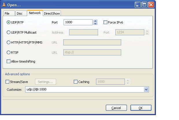
R

Disclaimer:
Xilinx is disclosing this user guide, manual, release note, and/or specification (the “Documentation”) to you solely for use in the development
of designs to operate with Xilinx hardware devices. You may not reproduce, distribute, republish, download, display, post, or transmit the
Documentation in any form or by any means including, but not limited to, electronic, mechanical, photocopying, recording, or otherwise,
without the prior written consent of Xilinx. Xilinx expressly disclaims any liability arising out of your use of the Documentation. Xilinx reserves
the right, at its sole discretion, to change the Documentation without notice at any time. Xilinx assumes no obligation to correct any errors
contained in the Documentation, or to advise you of any corrections or updates. Xilinx expressly disclaims any liability in connection with
technical support or assistance that may be provided to you in connection with the Information. THE DOCUMENTATION IS DISCLOSED TO
YOU “AS-IS” WITH NO WARRANTY OF ANY KIND. XILINX MAKES NO OTHER WARRANTIES, WHETHER EXPRESS, IMPLIED, OR
STATUTORY, REGARDING THE DOCUMENTATION, INCLUDING ANY WARRANTIES OF MERCHANTABILITY, FITNESS FOR A
PARTICULAR PURPOSE, OR NONINFRINGEMENT OF THIRD-PARTY RIGHTS. IN NO EVENT WILL XILINX BE LIABLE FOR ANY
CONSEQUENTIAL, INDIRECT, EXEMPLARY, SPECIAL, OR INCIDENTAL DAMAGES, INCLUDING ANY LOSS OF DATA OR LOST
PROFITS, ARISING FROM YOUR USE OF THE DOCUMENTATION.
© 2008–2009 Xilinx, Inc. All rights reserved.
XILINX, the Xilinx logo, the Brand Window, and other designated brands included herein are trademarks of Xilinx, Inc. All other trademarks
are the property of their respective owners.

Revision History
The following table shows the revision history for this document.

      Date             Version                                                         Revision
     2/22/08              1.0          Initial Xilinx release.
     5/2/08               1.1          Updated to Reflect V1.01 Hardware Platform
     5/27/08              1.2          Made content edits in Chapter 4; updated figure 4_2.
     1/20/09              2.0          Migrated to EDK tools; updated from MPMC2 to MPMC version4; added IGMP/Multicast.

Video Over IP User Guide                                         www.xilinx.com                              UG463 (v2.0) January 20, 2009
Table of Contents
Preface: About This Guide
Guide Contents . . . . . . . . . . . . . . . . . . . . . . . . . . . . . . . . . . . . . . . . . . . . . . . . . . . . . . . . . . . . . . . 7
Additional Resources . . . . . . . . . . . . . . . . . . . . . . . . . . . . . . . . . . . . . . . . . . . . . . . . . . . . . . . . . . 7
Conventions . . . . . . . . . . . . . . . . . . . . . . . . . . . . . . . . . . . . . . . . . . . . . . . . . . . . . . . . . . . . . . . . . . 7
Typographical . . . . . . . . . . . . . . . . . . . . . . . . . . . . . . . . . . . . . . . . . . . . . . . . . . . . . . . . . . . . . . 7
Online Document . . . . . . . . . . . . . . . . . . . . . . . . . . . . . . . . . . . . . . . . . . . . . . . . . . . . . . . . . . . 8
Chapter 1: Video Over IP Overview
Introduction . . . . . . . . . . . . . . . . . . . . . . . . . . . . . . . . . . . . . . . . . . . . . . . . . . . . . . . . . . . . . . . . . . 9
Video Over IP Fundamentals. . . . . . . . . . . . . . . . . . . . . . . . . . . . . . . . . . . . . . . . . . . . . . . . . . . 9
Network Protocols . . . . . . . . . . . . . . . . . . . . . . . . . . . . . . . . . . . . . . . . . . . . . . . . . . . . . . . . . . 9
Video Terms . . . . . . . . . . . . . . . . . . . . . . . . . . . . . . . . . . . . . . . . . . . . . . . . . . . . . . . . . . . . . . 10
EDK . . . . . . . . . . . . . . . . . . . . . . . . . . . . . . . . . . . . . . . . . . . . . . . . . . . . . . . . . . . . . . . . . . . . . . . . 11
Multiport Memory Controller (MPMC) . . . . . . . . . . . . . . . . . . . . . . . . . . . . . . . . . . . . . . . . 11
Port Configuration . . . . . . . . . . . . . . . . . . . . . . . . . . . . . . . . . . . . . . . . . . . . . . . . . . . . . . . . . 11
Configuring the MPMC . . . . . . . . . . . . . . . . . . . . . . . . . . . . . . . . . . . . . . . . . . . . . . . . . . . . . 11
Chapter 2: ASI to IP Bridge (Transmitter)
Introduction . . . . . . . . . . . . . . . . . . . . . . . . . . . . . . . . . . . . . . . . . . . . . . . . . . . . . . . . . . . . . . . . . 13
Features . . . . . . . . . . . . . . . . . . . . . . . . . . . . . . . . . . . . . . . . . . . . . . . . . . . . . . . . . . . . . . . . . . . . . 13
Functional Description. . . . . . . . . . . . . . . . . . . . . . . . . . . . . . . . . . . . . . . . . . . . . . . . . . . . . . . . 13
Version . . . . . . . . . . . . . . . . . . . . . . . . . . . . . . . . . . . . . . . . . . . . . . . . . . . . . . . . . . . . . . . . . . . . . . 13
Overview . . . . . . . . . . . . . . . . . . . . . . . . . . . . . . . . . . . . . . . . . . . . . . . . . . . . . . . . . . . . . . . . . . . . 14
Hardware Platform . . . . . . . . . . . . . . . . . . . . . . . . . . . . . . . . . . . . . . . . . . . . . . . . . . . . . . . . . . 14
Network Configuration . . . . . . . . . . . . . . . . . . . . . . . . . . . . . . . . . . . . . . . . . . . . . . . . . . . . . . . 14
IP Addresses . . . . . . . . . . . . . . . . . . . . . . . . . . . . . . . . . . . . . . . . . . . . . . . . . . . . . . . . . . . . . . 14
UDP Ports . . . . . . . . . . . . . . . . . . . . . . . . . . . . . . . . . . . . . . . . . . . . . . . . . . . . . . . . . . . . . . . . 14
MAC Addresses . . . . . . . . . . . . . . . . . . . . . . . . . . . . . . . . . . . . . . . . . . . . . . . . . . . . . . . . . . . 15
RS-232 Commands . . . . . . . . . . . . . . . . . . . . . . . . . . . . . . . . . . . . . . . . . . . . . . . . . . . . . . . . . . . 15
Identify Command: “?” . . . . . . . . . . . . . . . . . . . . . . . . . . . . . . . . . . . . . . . . . . . . . . . . . . . . . . 15
Read Command: “rAA” . . . . . . . . . . . . . . . . . . . . . . . . . . . . . . . . . . . . . . . . . . . . . . . . . . . . . 15
Write Command: “wAADD” . . . . . . . . . . . . . . . . . . . . . . . . . . . . . . . . . . . . . . . . . . . . . . . . . 15
Get Command: “g” . . . . . . . . . . . . . . . . . . . . . . . . . . . . . . . . . . . . . . . . . . . . . . . . . . . . . . . . . 15
Channel Specific Registers Definition . . . . . . . . . . . . . . . . . . . . . . . . . . . . . . . . . . . . . . . . . . 15
Base Address Map For Each Channel . . . . . . . . . . . . . . . . . . . . . . . . . . . . . . . . . . . . . . . . . . 16
Offset 0x00, Control Register . . . . . . . . . . . . . . . . . . . . . . . . . . . . . . . . . . . . . . . . . . . . . . . . . 16
Offset 0x01: L Value Register . . . . . . . . . . . . . . . . . . . . . . . . . . . . . . . . . . . . . . . . . . . . . . . . 17
Offset 0x02: D Value Register . . . . . . . . . . . . . . . . . . . . . . . . . . . . . . . . . . . . . . . . . . . . . . . . 17
Offset 0x03 - 0x06: SSRC Register . . . . . . . . . . . . . . . . . . . . . . . . . . . . . . . . . . . . . . . . . . . . 17
Offset 0x07 - 0x08: Destination UDP Port Register . . . . . . . . . . . . . . . . . . . . . . . . . . . . . . . . 18
Offset 0x09 - 0x0C: Destination IP Address Register . . . . . . . . . . . . . . . . . . . . . . . . . . . . . . 18
Offset 0x0D - 0x12: Destination MAC Address Register . . . . . . . . . . . . . . . . . . . . . . . . . . . 18
Offset 0x13: ASI Input Statistics Register . . . . . . . . . . . . . . . . . . . . . . . . . . . . . . . . . . . . . . . 19
Offset 0x14: Status/Clear Register . . . . . . . . . . . . . . . . . . . . . . . . . . . . . . . . . . . . . . . . . . . . . 20
Offset 0x15: Packet Drop Register . . . . . . . . . . . . . . . . . . . . . . . . . . . . . . . . . . . . . . . . . . . . . 21
Offset 0x16 - 0x17: Packet Drop Interval Register . . . . . . . . . . . . . . . . . . . . . . . . . . . . . . . . 21
3 www.xilinx.com Video Over IP User Guide
UG463 (v2.0) January 20, 2009Common Registers Definitions . . . . . . . . . . . . . . . . . . . . . . . . . . . . . . . . . . . . . . . . . . . . . . . . 21
Addresses 0x1A - 0x1F: Source MAC Address Register . . . . . . . . . . . . . . . . . . . . . . . . . . . . 22
Addresses 0x3A - 0x3D: Source IP Address Registers . . . . . . . . . . . . . . . . . . . . . . . . . . . . . 22
Addresses 0x3E - 0x3F: Source UDP Port Register . . . . . . . . . . . . . . . . . . . . . . . . . . . . . . . . 23
Address 0xFC: Statistics Read Address Register . . . . . . . . . . . . . . . . . . . . . . . . . . . . . . . . . . 23
Addresses 0xFD - 0xFF: Hardware Version Register . . . . . . . . . . . . . . . . . . . . . . . . . . . . . . 23
Statistic Address 0x04 - 0x06: Transport Stream Packets Count Register . . . . . . . . . . . . . . . 24
Statistic Address 0x08 - 0x09: Sync Byte Lost Count Register . . . . . . . . . . . . . . . . . . . . . . . 24
Statistic Address 0x0A: Data Status Register . . . . . . . . . . . . . . . . . . . . . . . . . . . . . . . . . . . . . 24
Statistic Address 0x0C - 0x0E: ASI Recovery Error Count Register . . . . . . . . . . . . . . . . . . . 25
Design Parameters . . . . . . . . . . . . . . . . . . . . . . . . . . . . . . . . . . . . . . . . . . . . . . . . . . . . . . . . . . . 25
Detailed Parameter Descriptions. . . . . . . . . . . . . . . . . . . . . . . . . . . . . . . . . . . . . . . . . . . . . . . 25
External DDR Memory . . . . . . . . . . . . . . . . . . . . . . . . . . . . . . . . . . . . . . . . . . . . . . . . . . . . . . . 26
Memory Bandwidth . . . . . . . . . . . . . . . . . . . . . . . . . . . . . . . . . . . . . . . . . . . . . . . . . . . . . . . . 26
Building Hardware . . . . . . . . . . . . . . . . . . . . . . . . . . . . . . . . . . . . . . . . . . . . . . . . . . . . . . . . . . . 26
Directory Structure . . . . . . . . . . . . . . . . . . . . . . . . . . . . . . . . . . . . . . . . . . . . . . . . . . . . . . . . . 27
Source Files . . . . . . . . . . . . . . . . . . . . . . . . . . . . . . . . . . . . . . . . . . . . . . . . . . . . . . . . . . . . . . . 27
Libraries . . . . . . . . . . . . . . . . . . . . . . . . . . . . . . . . . . . . . . . . . . . . . . . . . . . . . . . . . . . . . . . . . 27
Typical Modifications . . . . . . . . . . . . . . . . . . . . . . . . . . . . . . . . . . . . . . . . . . . . . . . . . . . . . . . 28
EDK Version . . . . . . . . . . . . . . . . . . . . . . . . . . . . . . . . . . . . . . . . . . . . . . . . . . . . . . . . . . . . . . 28
Block Diagrams . . . . . . . . . . . . . . . . . . . . . . . . . . . . . . . . . . . . . . . . . . . . . . . . . . . . . . . . . . . . . . 29
Test Modes . . . . . . . . . . . . . . . . . . . . . . . . . . . . . . . . . . . . . . . . . . . . . . . . . . . . . . . . . . . . . . . . . . 33
Known Issues . . . . . . . . . . . . . . . . . . . . . . . . . . . . . . . . . . . . . . . . . . . . . . . . . . . . . . . . . . . . . . . . 33
Limitations . . . . . . . . . . . . . . . . . . . . . . . . . . . . . . . . . . . . . . . . . . . . . . . . . . . . . . . . . . . . . . . . . . 33
FPGA Resources . . . . . . . . . . . . . . . . . . . . . . . . . . . . . . . . . . . . . . . . . . . . . . . . . . . . . . . . . . . . . 33
Chapter 3: IP to ASI Bridge (Receiver)
Introduction . . . . . . . . . . . . . . . . . . . . . . . . . . . . . . . . . . . . . . . . . . . . . . . . . . . . . . . . . . . . . . . . . 35
Features . . . . . . . . . . . . . . . . . . . . . . . . . . . . . . . . . . . . . . . . . . . . . . . . . . . . . . . . . . . . . . . . . . . . . 35
Functional Description. . . . . . . . . . . . . . . . . . . . . . . . . . . . . . . . . . . . . . . . . . . . . . . . . . . . . . . . 35
Version . . . . . . . . . . . . . . . . . . . . . . . . . . . . . . . . . . . . . . . . . . . . . . . . . . . . . . . . . . . . . . . . . . . . . . 35
Overview . . . . . . . . . . . . . . . . . . . . . . . . . . . . . . . . . . . . . . . . . . . . . . . . . . . . . . . . . . . . . . . . . . . . 36
Hardware Platform . . . . . . . . . . . . . . . . . . . . . . . . . . . . . . . . . . . . . . . . . . . . . . . . . . . . . . . . . . 36
Network Configuration . . . . . . . . . . . . . . . . . . . . . . . . . . . . . . . . . . . . . . . . . . . . . . . . . . . . . . . 36
IP Addresses . . . . . . . . . . . . . . . . . . . . . . . . . . . . . . . . . . . . . . . . . . . . . . . . . . . . . . . . . . . . . . 36
UDP Ports . . . . . . . . . . . . . . . . . . . . . . . . . . . . . . . . . . . . . . . . . . . . . . . . . . . . . . . . . . . . . . . . 36
MAC Addresses . . . . . . . . . . . . . . . . . . . . . . . . . . . . . . . . . . . . . . . . . . . . . . . . . . . . . . . . . . . 36
IGMP. . . . . . . . . . . . . . . . . . . . . . . . . . . . . . . . . . . . . . . . . . . . . . . . . . . . . . . . . . . . . . . . . . . . 37
RS-232 Commands . . . . . . . . . . . . . . . . . . . . . . . . . . . . . . . . . . . . . . . . . . . . . . . . . . . . . . . . . . . 37
Identify Command: “?” . . . . . . . . . . . . . . . . . . . . . . . . . . . . . . . . . . . . . . . . . . . . . . . . . . . . . . 37
Read Command: “rAA” . . . . . . . . . . . . . . . . . . . . . . . . . . . . . . . . . . . . . . . . . . . . . . . . . . . . . 37
Write Command: “wAADD” . . . . . . . . . . . . . . . . . . . . . . . . . . . . . . . . . . . . . . . . . . . . . . . . . 37
Get Command: “g” . . . . . . . . . . . . . . . . . . . . . . . . . . . . . . . . . . . . . . . . . . . . . . . . . . . . . . . . . 37
Channel Specific Registers Definition . . . . . . . . . . . . . . . . . . . . . . . . . . . . . . . . . . . . . . . . . . 37
Base Address Map For Each Channel . . . . . . . . . . . . . . . . . . . . . . . . . . . . . . . . . . . . . . . . . . 38
Offset 0x00: Control Register . . . . . . . . . . . . . . . . . . . . . . . . . . . . . . . . . . . . . . . . . . . . . . . . . 38
Offset 0x01: Status Register 1 . . . . . . . . . . . . . . . . . . . . . . . . . . . . . . . . . . . . . . . . . . . . . . . . 39
Video Over IP User Guide www.xilinx.com 4
UG463 (v2.0) January 20, 2009Offset 0x02: Status Register 2 . . . . . . . . . . . . . . . . . . . . . . . . . . . . . . . . . . . . . . . . . . . . . . . . 39
Offset 0x03 - 0x06: SSRC Firewall Register . . . . . . . . . . . . . . . . . . . . . . . . . . . . . . . . . . . . . 39
Offset 0x07 - 0x08: Source UDP Port Register . . . . . . . . . . . . . . . . . . . . . . . . . . . . . . . . . . . 40
Offset 0x09 - 0x0C: Source IP Address Firewall Register . . . . . . . . . . . . . . . . . . . . . . . . . . . 40
Offset 0x0D - 0x0F: IP Packet Count Received Register . . . . . . . . . . . . . . . . . . . . . . . . . . . . 41
Offset 0x10 - 0x12: ASI Output Rate Register . . . . . . . . . . . . . . . . . . . . . . . . . . . . . . . . . . . . 41
Offset 0x13 - 0x15: Missing Media Packet Count Register . . . . . . . . . . . . . . . . . . . . . . . . . . 41
Offset 0x16 - 0x17: Program Identifier (PID) Control Register . . . . . . . . . . . . . . . . . . . . . . . 42
Offset 0x18 - 0x19: Continuity Count (CC) Error Count Register . . . . . . . . . . . . . . . . . . . . . 42
Offset 0x1A - 0x1C: Packets Recovered with FEC Register . . . . . . . . . . . . . . . . . . . . . . . . . 42
Common Registers Definitions . . . . . . . . . . . . . . . . . . . . . . . . . . . . . . . . . . . . . . . . . . . . . . . . 42
Board MAC Address Register . . . . . . . . . . . . . . . . . . . . . . . . . . . . . . . . . . . . . . . . . . . . . . . . 43
Board IP Address Register . . . . . . . . . . . . . . . . . . . . . . . . . . . . . . . . . . . . . . . . . . . . . . . . . . . 43
Multicast IP Address Register . . . . . . . . . . . . . . . . . . . . . . . . . . . . . . . . . . . . . . . . . . . . . . . . 44
Monitored UDP Port Register . . . . . . . . . . . . . . . . . . . . . . . . . . . . . . . . . . . . . . . . . . . . . . . . . 44
Hardware Version Register . . . . . . . . . . . . . . . . . . . . . . . . . . . . . . . . . . . . . . . . . . . . . . . . . . . 44
Design Parameters . . . . . . . . . . . . . . . . . . . . . . . . . . . . . . . . . . . . . . . . . . . . . . . . . . . . . . . . . . . 45
Detailed Parameter Descriptions. . . . . . . . . . . . . . . . . . . . . . . . . . . . . . . . . . . . . . . . . . . . . . . 45
External DDR Memory . . . . . . . . . . . . . . . . . . . . . . . . . . . . . . . . . . . . . . . . . . . . . . . . . . . . . . . 46
Memory Bandwidth . . . . . . . . . . . . . . . . . . . . . . . . . . . . . . . . . . . . . . . . . . . . . . . . . . . . . . . . 46
Algorithms . . . . . . . . . . . . . . . . . . . . . . . . . . . . . . . . . . . . . . . . . . . . . . . . . . . . . . . . . . . . . . . . . . 46
NCO Adjustment . . . . . . . . . . . . . . . . . . . . . . . . . . . . . . . . . . . . . . . . . . . . . . . . . . . . . . . . . . 46
FIFO Metering . . . . . . . . . . . . . . . . . . . . . . . . . . . . . . . . . . . . . . . . . . . . . . . . . . . . . . . . . . . . 47
Building Hardware . . . . . . . . . . . . . . . . . . . . . . . . . . . . . . . . . . . . . . . . . . . . . . . . . . . . . . . . . . . 47
Directory Structure . . . . . . . . . . . . . . . . . . . . . . . . . . . . . . . . . . . . . . . . . . . . . . . . . . . . . . . . . 48
Source Files . . . . . . . . . . . . . . . . . . . . . . . . . . . . . . . . . . . . . . . . . . . . . . . . . . . . . . . . . . . . . . . 48
Libraries . . . . . . . . . . . . . . . . . . . . . . . . . . . . . . . . . . . . . . . . . . . . . . . . . . . . . . . . . . . . . . . . . 48
Typical Modifications . . . . . . . . . . . . . . . . . . . . . . . . . . . . . . . . . . . . . . . . . . . . . . . . . . . . . . . 49
EDK Version . . . . . . . . . . . . . . . . . . . . . . . . . . . . . . . . . . . . . . . . . . . . . . . . . . . . . . . . . . . . . . 50
Block Diagrams . . . . . . . . . . . . . . . . . . . . . . . . . . . . . . . . . . . . . . . . . . . . . . . . . . . . . . . . . . . . . . 50
Known Issues . . . . . . . . . . . . . . . . . . . . . . . . . . . . . . . . . . . . . . . . . . . . . . . . . . . . . . . . . . . . . . . . 53
Limitations . . . . . . . . . . . . . . . . . . . . . . . . . . . . . . . . . . . . . . . . . . . . . . . . . . . . . . . . . . . . . . . . . . 54
FPGA Resources . . . . . . . . . . . . . . . . . . . . . . . . . . . . . . . . . . . . . . . . . . . . . . . . . . . . . . . . . . . . . 54
Chapter 4: Video Over IP Testing
Introduction . . . . . . . . . . . . . . . . . . . . . . . . . . . . . . . . . . . . . . . . . . . . . . . . . . . . . . . . . . . . . . . . . 55
Test Equipment . . . . . . . . . . . . . . . . . . . . . . . . . . . . . . . . . . . . . . . . . . . . . . . . . . . . . . . . . . . . . . 55
Hardware . . . . . . . . . . . . . . . . . . . . . . . . . . . . . . . . . . . . . . . . . . . . . . . . . . . . . . . . . . . . . . . . . 55
Software . . . . . . . . . . . . . . . . . . . . . . . . . . . . . . . . . . . . . . . . . . . . . . . . . . . . . . . . . . . . . . . . . 56
Network Switches . . . . . . . . . . . . . . . . . . . . . . . . . . . . . . . . . . . . . . . . . . . . . . . . . . . . . . . . . . . . 56
Transport Stream Files . . . . . . . . . . . . . . . . . . . . . . . . . . . . . . . . . . . . . . . . . . . . . . . . . . . . . . . 56
Testing . . . . . . . . . . . . . . . . . . . . . . . . . . . . . . . . . . . . . . . . . . . . . . . . . . . . . . . . . . . . . . . . . . . . . . 56
Primary Test Modes . . . . . . . . . . . . . . . . . . . . . . . . . . . . . . . . . . . . . . . . . . . . . . . . . . . . . . . . 56
Test Success Criteria . . . . . . . . . . . . . . . . . . . . . . . . . . . . . . . . . . . . . . . . . . . . . . . . . . . . . . . . 57
Test Setup 1 - Basic Functionality and Data Throughput . . . . . . . . . . . . . . . . . . . . . . . . . . . . 57
Robustness Testing . . . . . . . . . . . . . . . . . . . . . . . . . . . . . . . . . . . . . . . . . . . . . . . . . . . . . . . . . 58
Jitter Testing . . . . . . . . . . . . . . . . . . . . . . . . . . . . . . . . . . . . . . . . . . . . . . . . . . . . . . . . . . . . . . 58
5 www.xilinx.com Video Over IP User Guide
UG463 (v2.0) January 20, 2009Chapter 5: Demonstrating the Video Over IP System
Introduction . . . . . . . . . . . . . . . . . . . . . . . . . . . . . . . . . . . . . . . . . . . . . . . . . . . . . . . . . . . . . . . . . 59
System Features . . . . . . . . . . . . . . . . . . . . . . . . . . . . . . . . . . . . . . . . . . . . . . . . . . . . . . . . . . . . . . 59
Reference System Specifics . . . . . . . . . . . . . . . . . . . . . . . . . . . . . . . . . . . . . . . . . . . . . . . . . . . . 60
Demonstrating the Reference System . . . . . . . . . . . . . . . . . . . . . . . . . . . . . . . . . . . . . . . . . . 60
Xilinx - XGI - 8 Ch SDI Video Module Setup . . . . . . . . . . . . . . . . . . . . . . . . . . . . . . . . . . . . 61
The Demonstrations . . . . . . . . . . . . . . . . . . . . . . . . . . . . . . . . . . . . . . . . . . . . . . . . . . . . . . . . 61
Physical Connections . . . . . . . . . . . . . . . . . . . . . . . . . . . . . . . . . . . . . . . . . . . . . . . . . . . . . . . 62
Performing the Demonstration . . . . . . . . . . . . . . . . . . . . . . . . . . . . . . . . . . . . . . . . . . . . . . . . 63
Debugging The System . . . . . . . . . . . . . . . . . . . . . . . . . . . . . . . . . . . . . . . . . . . . . . . . . . . . . . . 70
Ethernet NIC Issues . . . . . . . . . . . . . . . . . . . . . . . . . . . . . . . . . . . . . . . . . . . . . . . . . . . . . . . . 70
Defective SMA Cables . . . . . . . . . . . . . . . . . . . . . . . . . . . . . . . . . . . . . . . . . . . . . . . . . . . . . . 71
Receiver board LED indicators . . . . . . . . . . . . . . . . . . . . . . . . . . . . . . . . . . . . . . . . . . . . . . . . 71
Streaming Video Quality Issues . . . . . . . . . . . . . . . . . . . . . . . . . . . . . . . . . . . . . . . . . . . . . . . 72
Video Over IP User Guide www.xilinx.com 6
UG463 (v2.0) January 20, 2009R
Preface
About This Guide
Guide Contents
This user guide contains the following chapters:
Chapter 1, “Video Over IP Overview”
Chapter 2, “ASI to IP Bridge (Transmitter)”
Chapter 3, “IP to ASI Bridge (Receiver),”
Chapter 4, “Video Over IP Testing,”
Chapter 5, “Demonstrating the Video Over IP System”
Additional Resources
To request access to the reference systems associated with this user guide, visit:
https://secure.xilinx.com/webreg/register.do?group=video_ip.
To find additional documentation, see the Xilinx website at:
http://www.xilinx.com/literature.
To search the Answer Database of silicon, software, and IP questions and answers, or to create a
technical support WebCase, see the Xilinx website at:
http://www.xilinx.com/support.
Conventions
This document uses the following conventions. An example illustrates each convention.
Typographical
The following typographical conventions are used in this document:
Convention Meaning or Use Example
Messages, prompts, and program
Courier font speed grade: - 100
files that the system displays
Literal commands that you enter in
Courier bold ngdbuild design_name
a syntactical statement
Video Over IP User Guide www.xilinx.com 7
UG463 (v2.0) January 20, 2009R
Preface: About This Guide
Convention Meaning or Use Example
Commands that you select from a
File → Open
Helvetica bold menu
Keyboard shortcuts Ctrl+C
Variables in a syntax statement for
ngdbuild design_name
which you must supply values
See the Development System
References to other manuals Reference Guide for more
Italic font
information.
If a wire is drawn so that it overlaps
Emphasis in text the pin of a symbol, the two nets are
not connected.
An optional entry or parameter.
However, in bus specifications, ngdbuild [option_name]
Square brackets [ ]
such as bus[7:0], they are design_name
required.
A list of items from which you must
Braces { } lowpwr ={on|off}
choose one or more
Vertical bar | Separates items in a list of choices lowpwr ={on|off}
IOB #1: Name = QOUT’
Vertical ellipsis
IOB #2: Name = CLKIN’
. Repetitive material that has been
.
. omitted
.
.
.
Repetitive material that has been allow block block_name loc1
Horizontal ellipsis . . .
omitted loc2 ... locn;
Online Document
The following conventions are used in this document:
Convention Meaning or Use Example
See the section “Additional
Cross-reference link to a location in Resources” for details.
Blue text
the current document Refer to “Title Formats” in Chapter
1 for details.
Cross-reference link to a location in See Figure 2-5 in the Virtex-II
Red text
another document Platform FPGA User Guide.
Go to http://www.xilinx.com for the
Blue, underlined text Hyperlink to a website (URL)
latest speed files.
8 www.xilinx.com Video Over IP User Guide
UG463 (v2.0) January 20, 2009R
Chapter 1
Video Over IP Overview
Introduction
This chapter provides an overview of the Xilinx Video Over IP system.
Video Over IP Fundamentals
This section describes the fundamentals of Video Over IP independent of the Xilinx solution. It is
not intended to be a complete tutorial, but solely an introduction to Video Over IP.
Video Over IP is a system for transporting video and audio, usually compressed, from an input
source to a destination using IP protocol over Ethernet. UDP is the protocol used to transport video
over an IP network. RTP protocol on top of UDP may also be used and is required when FEC
(Forward Error Correction) standards are implemented.
Many Video Over IP systems provide a bridging function from one physical interface, such as ASI
or SDI, to IP over Ethernet or from IP over Ethernet to another physical interface.
The data to be transported is called a transport stream which consists of packets of 188 or 204 bytes.
A number of transport stream packets are encapsulated in IP packets to be transported over Ethernet.
These packets are transported continuously and unidirectionally without any back channel for
feedback or control.
Network Protocols
The following network protocols are used in some manner for Video Over IP.
UDP (User Datagram Protocol)
UDP is a low overhead connectionless transport protocol on top of IP protocol. Because packets are
sent to the Receiver without any confirmation that they were received, there is no reliability
mechanism built into the protocol.
RTP (Real-time Transport Protocol)
A protocol on top of UDP, used for video, which contains timestamps to help with synchronization.
RTP is needed when FEC is employed.
ARP (Address Resolution Protocol)
A protocol to determine the MAC address of a device on an IP network. This protocol can be used
such that the sender of data only needs to know the IP address of the destination, but not the MAC
address.
Video Over IP User Guide www.xilinx.com 9
UG463 (v2.0) January 20, 2009R
Chapter 1: Video Over IP Overview
IGMP (Internet Group Management Protocol)
A protocol to support multicast which allows a receiver of video to send a message to a router to join
a group. The router then sends multicast video data to all members of the group so that the
transmitter does not have to replicate the data for each receiver.
SNMP (Simple Network Management Protocol)
A protocol used to exchange management information between network devices.
Video Terms
Transport Stream
A transport stream refers to an MPEG transport stream which is a protocol for audio, video, and
data. The protocol is specified in the MPEG-2 specification. Data files for testing of the Video Over
IP system are typically called transport stream files.
When a transport stream is carried over IP, the packets of the transport stream are put into User
Datagram Packet (UDP) format together with an RTP header. From one to seven packets from the
transport stream are placed into the payload.
FEC (Forward Error Correction)
When video data is transported over longer distances, data can be lost. FEC sends extra data with the
media so that errors can be corrected by the Receiver.
SMPTE 2022
SMPTE 2022-1-2007, Forward Error Correction for Real-Time Video/Audio Transport Over IP
Networks and SMPTE 2022-2-2007, Unidirectional Transport of Constant Bit Rate MPEG-2
Transport Stream on IP network, together define packetizing video streams and adding forward error
correction..
ASI (Asynchronous Serial Interface)
ASI, sometimes referred to as DVB-ASI, is a digital video interface used for carrying compressed
video and audio streams. When the transport stream is on its physical link, it is serialized and
8B/10B coded for a 270 Mbps link but the maximum payload is 216 Mbps. This link contains live
transport stream data, but since the actual data link is usually running at < 216 Mbps, most of the
physical layer contains null bytes.
SDI (Serial Digital Interface)
SDI is a digital video interface used for uncompressed video.
PCR (Program Clock Reference)
The PCR is a field contained in the MPEG data to assist the decoder in presenting programs on time,
at the right speed, and with synchronization.
CC (Continuity Counter)
The continuity counter is a field contained in the MPEG data to allow the detection of lost data.
10 www.xilinx.com Video Over IP User Guide
UG463 (v2.0) January 20, 2009R
EDK
EDK
The ASI to IP (Transmitter) and IP to ASI (Receiver) are built using the Xilinx Embedded
Development Kit (EDK). Either project is opened through EDK by navigating to the top level
directory and selecting the XMP file for that project. Once opened in EDK either project can be
configured to change the number of channels or to include/exclude Forward Error Correction. For
more information see the “Getting Started with EDK” document available at www.xilinx.com
Multiport Memory Controller (MPMC)
The ASI to IP (Transmitter) and IP to ASI (Receiver) both use version 4 of the MPMC from the
Xilinx Embedded Development Kit (EDK). Each uses a slightly different configuration of the
MPMC with a different number of ports and different port memory interface, BRAM or SRL.
Documentation for the MPMC can be found at http://www.xilinx.com, and is also available through
EDK.
Port Configuration
The ASI to IP (Transmitter) requires a single NPI port on the MPMC for use with FEC. The NPI port
is configured to use BRAM for the packet FIFOs. The MPMC used by the ASI to IP has a 64-bit data
interface to the DDR and a 64-bit data interface to the NPI port. The ASI to IP uses the DDR for
storing FEC data.
The IP to ASI (Receiver) requires 3 NPI ports on the MPMC. All NPI ports are configured to use
SRL FIFOs to help minimize the size of the MPMC. The MPMC used by the IP to ASI has a 64-bit
data interface to the DDR and a 64-bit data interface to each NPI port. FEC packets and media
packets are stored in DDR by the IP to ASI.
Configuring the MPMC
Should the MPMC need to be re-configured, for example to add ports for a processor interface, it is
important to keep the ports as defined above for the Transmitter and Receiver. This is due to
potential latency differences between BRAM and SRL.
The MPMC is configured from within the EDK by right clicking on the DDR_SDRAM in the
System Assembly View tab.
Video Over IP User Guide www.xilinx.com 11
UG463 (v2.0) January 20, 2009R
Chapter 1: Video Over IP Overview
12 www.xilinx.com Video Over IP User Guide
UG463 (v2.0) January 20, 2009R
Chapter 2
ASI to IP Bridge (Transmitter)
Introduction
This chapter describes the ASI to IP Bridge, also referred to as the Transmitter. This reference
system takes from 1 - 8 ASI inputs and encapsulates each transport stream data into a single IP
stream output on gigabit Ethernet.
To request access to the Transmitter reference system, visit:
https://secure.xilinx.com/webreg/register.do?group=video_ip
Decision to grant access will be made on an individual basis.
Features
The Transmitter reference system has the following features.
• 1 to 8 channels of ASI input, full bandwidth up to 1 Gigabit aggregate
• IP output on gigabit Ethernet using the hard TEMAC
• SMPTE 2022-1-2007 and SMPTE 2022-2-2007
• Multi Channel FEC support
• ARP protocol support
• IGMP version 2 support
• No processor is required or included
• Serial control and diagnostics
• Virtex®-5 LXT Platform support
• ASI inputs verified to be operational for a range of 2.5 - 208 Mbps per channel
Functional Description
The ASI to IP Bridge (Transmitter) takes transport stream data from up to 8 ASI inputs and bridges
the data to a gigabit Ethernet interface. It recovers the 10-bit ASI data for each ASI input, decodes
it to 8-bit transport stream data, writes the transport stream data into memory, encapsulates up to 7
transport stream packets into an IP packet with UDP and RTP headers, and sends the data out the
gigabit Ethernet interface.
Version
This document applies to version 2.00 of the hardware.
Video Over IP User Guide www.xilinx.com 13
UG463 (v2.0) January 20, 2009R
Chapter 2: ASI to IP Bridge (Transmitter)
Overview
The key functional blocks of the design are shown in Figure 2-1.
Hardware Platform
This reference system runs on the Xilinx ML505 board which is available from Xilinx.
http://www.xilinx.com/ml505
It also requires an 8 channel ASI daughter card from Cook Technologies which is referred to as the
CT8ASI 8 Channel DVB-ASI Daughter Card.
http://www.cook-tech.com/ct8asi.html
The daughter card has 8 input BNC connectors on it labelled RX1 to RX8 and 8 output BNC
connectors on it labelled TX1 to TX8.
In the HDL design of the Transmitter and a lot of the documentation, channels are numbered from
0 to 7 which can be confusing since the daughter card connectors are numbered from 1 to 8.
Network Configuration
IP Addresses
The Transmitter defaults to 192.168.1.100 as its source IP address. For channels 0 - 3, it sends data
to IP address 192.168.1.102. For channels 4 - 7, it sends data to 192.168.1.101.
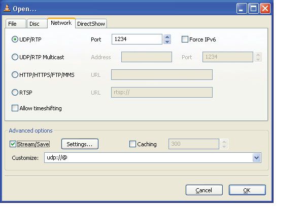
UDP Ports
The Transmitter defaults to port 1234 as its source UDP port. Table 2-1 contains the destination
UDP ports for each channel.
Table 2-1: Channel Destination UDP Ports
Daughter Board BNC Connector Channel Destination UDP Port
RX1 0 1000
RX2 1 2000
RX3 2 3000
RX4 3 4000
RX5 4 5000
RX6 5 6000
RX7 6 7000
RX8 7 8000
MAC Addresses
The Transmitter defaults to 0xD00DBEEFD00D for its source MAC address. By default it uses
Address Resolution Protocol (ARP) to determine the MAC address of the destination IP address. If
14 www.xilinx.com Video Over IP User Guide
UG463 (v2.0) January 20, 2009R
RS-232 Commands
the destination is a multicast address, the destination MAC address will be set as per the Internet
Group Management Protocol (IGMP) specification. In lieu of using the MAC address provided by
ARP, the destination MAC addresses can also be overridden by writing the desired MAC address in
the Destination MAC Address Register and configuring the Control Register appropriately.
RS-232 Commands
The Transmitter design contains a set of registers which can be read and written, or both, using the
RS-232 interface. The registers control the operation of the device and indicate the status of the
device. The UART is configured for 57600 baud, 1 stop bit, 8 data bits, and parity of None. A
dumb terminal can be used to communicate with the device.
Identify Command: “?”
The ‘?’ character causes the Transmitter to output an ID prompt to the RS-232 interface. The ID
prompt indicates the Transmitter and the version of the hardware.
Read Command: “rAA”
The ‘r’ character followed by two additional address characters cause the device to output the
register contents for the hex address specified by AA.
Write Command: “wAADD”
The ‘w’ character followed by two additional address characters and two additional data characters
cause the device to write the value specified by DD to the hex address specified by AA.
Get Command: “g”
The ‘g’ character causes the Transmitter to dump the contents of all the registers from address 0 to
FF.
Channel Specific Registers Definition
The following text describes the registers which are contained in the Transmitter.
Each register at each address is a byte wide with the most significant bit being bit 7 and least
significant bit being bit 0 (i.e. [7:0]).
Offsets for each register are specified rather than an address. The offset must be added to the base
address of the channel to get the actual register address for a channel.
Base Address Map For Each Channel
Table 2-2: Channel Base Address
Channel Base Address
0 0x00
1 0x20
2 0x40
Video Over IP User Guide www.xilinx.com 15
UG463 (v2.0) January 20, 2009R
Chapter 2: ASI to IP Bridge (Transmitter)
Table 2-2: Channel Base Address (Cont’d)
Channel Base Address
3 0x60
4 0x80
5 0xA0
6 0xC0
7 0xE0
Offset 0x00, Control Register
This register controls many of the primary functions of the Transmitter.
Non-block aligned FEC is currently not supported. Transport Stream Packet Size defines the input
ASI packet size. Destination MAC Address can be resolved by using ARP or the value written to
destination MAC address register can be used. The number of TS packets per IP packet must be the
same for all channels.
Table 2-3: Control Register
Bit(s) Name Access Reset Value Description
1 = block aligned
7 FEC Alignment Read/Write 1
0 = non-block aligned
Transport Stream 1 = 188 bytes
6 Read/Write 1
Packet Size 0 = 204 bytes
Destination MAC 1 = from register
5 Read/Write 0
Address 0 = from ARP
1 = enabled
4 Row FEC Read/Write 1
0 = disabled
1 = enabled
3 Column FEC Read/Write 1
0 = disabled
TS Packets per IP
2-0 Read/Write 7 1-7
Packet
16 www.xilinx.com Video Over IP User Guide
UG463 (v2.0) January 20, 2009R
Channel Specific Registers Definition
Offset 0x01: L Value Register
The hardware checks the L value and ensures that 1R
Chapter 2: ASI to IP Bridge (Transmitter)
Offset 0x07 - 0x08: Destination UDP Port Register
Two consecutive byte registers together form a 16-bit register containing the UDP destination port
that is inserted into the UDP header of each packet.The default value for destination port 1 is 1000,
for destination port 2 is 2000, etc.
Table 2-7: Destination UDP Port Register
Offset Bit(s) Name Access Reset Value Description
See register
Destination UDP The most significant byte of
0x07 7-0 Read/Write description
Port[15:8] the destination UDP port.
above.
See register
Destination UDP The least significant byte of
0x08 7-0 Read/Write description
Port[7:0] the destination UDP port.
above.
Offset 0x09 - 0x0C: Destination IP Address Register
Four consecutive byte registers together form a 32-bit register containing the Destination IP Address
that is that is inserted into the IP header of each packet.
Table 2-8: Destination IP Address Register
Offset Bit(s) Name Access Reset Value Description
The first (most significant)
Destination IP
0x09 7-0 Read/Write 0xC0 byte of the Destination IP
Address[31:24]
Address.
Destination IP The second byte of the
0x0A 7-0 Read/Write 0xA8
Address[23:16] Destination IP Address.
Destination IP The third byte of the
0x0B 7-0 Read/Write 0x01
Address[15:8] Destination IP Address.
0x66 for
Destination IP channels 0 - 3, The fourth byte of the
0x0C 7-0 Read/Write
Address[7:0] 0x65 for Destination IP Address.
channels 4 - 7
The default destination IP address for channels 0 - 3 is 192.168.1.102 and for channels 4 - 7 is
192.168.1.101. The purpose of these destination IP addresses is to better facilitate demonstrating the
Transmitter together with the Receiver and a PC.
Offset 0x0D - 0x12: Destination MAC Address Register
Six consecutive byte registers together form a 48-bit register containing the destination MAC
address that is inserted into the Ethernet header of each packet. This register value is only used when
the Control Register bit 5 is 1 and the destination IP address is not a multicast address.
If the Control register bit 5 is 0, writing to the Destination MAC Address Register does not change
the MAC address used for transmitting packets. For unicast destination IP addresses, ARP protocol
is used to determine the MAC address. If the destination is a multicast IP address, the destination
MAC address will be set as per the IGMP v.2 specification.
18 www.xilinx.com Video Over IP User Guide
UG463 (v2.0) January 20, 2009R
Channel Specific Registers Definition
If the Control register bit 5 is 1, the MAC used for transmitting packets is read from this register
unless the destination IP address is a multicast address, in which case the MAC address used for
transmitting is set as per the IGMP v.2 specification.
Reading the Destination MAC Address Register always returns the actual MAC used for
transmitting packets.
Table 2-9: Destination MAC Address Register
Reset
Offset Bit(s) Name Access Description
Value
Destination MAC The first byte of the
0x0D 7-0 Read/Write 0xC0
Address[47:40] Destination MAC Address.
Destination MAC The second byte of the
0x0E 7-0 Read/Write 0xED
Address[39:32] Destination MAC Address.
Destination MAC The third byte of the
0x0F 7-0 Read/Write 0xBE
Address[31:24] Destination MAC Address.
Destination MAC The fourth byte of the
0x10 7-0 Read/Write 0xEF
Address[23:16] Destination MAC Address
Destination MAC The fifth byte of the
0x11 7-0 Read/Write 0xCA
Address[15:8] Destination MAC Address
Destination MAC The sixth byte of the
0x12 7-0 Read/Write 0xFE
Address[7:0] Destination MAC Address
Offset 0x13: ASI Input Statistics Register
This register helps expand the number of registers in the memory map by providing a level of
indirection through the Stats Read Address register.
Table 2-10: ASI Input Statistics Register
Reset
Bit(s) Name Access Description
Value
ASI Input The value in this registers depends on the
7-0 Read Only X
Statistics Stat Read Address register.
Offset 0x14: Status/Clear Register
This register contains status information when read and allows other information to be cleared when
written to such that the read and write definitions are different.
Table 2-11: Status/Clear Register
Reset
Bit(s) Name Access Description
Value
7-4 Unused 0 Unused
Transport 1 = no valid transport stream data for ~8 ms
3 Read Only 0
Stream Alarm 0 = a valid transport stream is being received
Video Over IP User Guide www.xilinx.com 19
UG463 (v2.0) January 20, 2009R
Chapter 2: ASI to IP Bridge (Transmitter)
Table 2-11: Status/Clear Register (Cont’d)
Reset
Bit(s) Name Access Description
Value
Transport 1 = an overflow occurred
2 Stream RAM Read Only 0
Overflow 0 = no overflow
Sync Byte 1 = a sync byte (0x47) has been received
1 Read Only 0
Locked 0 = no sync byte has been received
1 = an input signal is being received by the
0 Carrier Detect Read Only 0 channel
0 - no input signal
The write definition of the register is shown in Table 2-12. Each bit in this register is self-clearing
after it is set.
Table 2-12: Register Write Definition
Reset
Bit(s) Name Access Description
Value
7-3 Unused 0 Unused
Transport Stream
Writing a 1 to this bit clears the
2 RAM Overflow Status Write Only 0
overflow status
Clear
ASI Recovery Error Writing a 1 to this bit clears the
1 Write Only 0
Count Clear error count
Sync Lost Byte Counter Writing a 1 to this bit clears the
0 Write Only 0
Clear lost byte count
Offset 0x15: Packet Drop Register
This register controls the packet drop function of the Transmitter.
Table 2-13: Packet Drop Register
Reset
Bit(s) Name Access Description
Value
7-3 Unused 0 Unused
1 = Disable transmission from this ASI input
Channel Read/ Write channel
2 0
Disable 0 = Transmision is enabled from this ASI
input channel
1 = Drop FEC packets along with TS packets
FEC Packet 0 = Do not drop any FEC packets
1 Read/ Write 0
Drop Enable This bit is only used when Packet Drop
Enable bit is set to 0
1 = Enable packet dropping in general and
Packet Drop Read/ Write
0 0 drop TS packets
Enable
0 = Do not drop any packets
20 www.xilinx.com Video Over IP User Guide
UG463 (v2.0) January 20, 2009R
Common Registers Definitions
Offset 0x16 - 0x17: Packet Drop Interval Register
Two consecutive byte registers together form a 16-bit register that controls the interval between each
packet drop. The interval is measured in number of packets.
Table 2-14: Packet Drop Interval Register
Reset
Offset Bit(s) Name Access Description
Value
The first byte (most significant)
0x16 7-0 Interval[15:8] Read/Write 0x00
of the interval value.
The last byte (least significant)
0x17 7-0 Interval[7:0] Read/Write 0x0A
of the interval value.
Common Registers Definitions
The following definitions are for the registers which are not channel specific and apply to all the
channels. The address for each register is the actual address rather than an offset from a base address
as with the channel specific registers.
Addresses 0x1A - 0x1F: Source MAC Address Register
Six consecutive byte registers together form a 48-bit register containing the source MAC address
that is inserted into the Ethernet header of each packet.
Table 2-15: Source MAC Address Register
Reset
Offset Bit(s) Name Access Description
Value
Source MAC The first byte of the Source
0x1A 7-0 Read/Write 0xD0
Address[47:40] MAC Address.
Source MAC The second byte of the
0x1B 7-0 Read/Write 0x0D
Address[39:32] Source MAC Address.
Source MAC The third byte of the Source
0x1C 7-0 Read/Write 0xBE
Address[31:24] MAC Address.
Source MAC The fourth byte of the
0x1D 7-0 Read/Write 0xEF
Address[23:16] Source MAC Address
Source MAC The fifth byte of the Source
0x1E 7-0 Read/Write 0xD0
Address[15:8] MAC Address
Source MAC The sixth byte of the Source
0x1F 7-0 Read/Write 0x0D
Address[7:0] MAC Address
Video Over IP User Guide www.xilinx.com 21
UG463 (v2.0) January 20, 2009R
Chapter 2: ASI to IP Bridge (Transmitter)
Addresses 0x3A - 0x3D: Source IP Address Registers
Four consecutive byte registers together form a 32-bit register containing the source IP address that
is that is inserted into the IP header of each packet. The default source IP address is 192.168.1.100.
Table 2-16: Source IP Address Register
Offset Bit(s) Name Access Reset Value Description
Source IP The first byte of the Source
0x3A 7-0 Read/Write 0xC0
Address[31:24] IP Address.
Source IP The second byte of the
0x3B 7-0 Read/Write 0xA8
Address[23:16] Source IP Address.
Source IP The third byte of the Source
0x3C 7-0 Read/Write 0x01
Address[15:8] IP Address.
Source IP The fourth byte of the Source
0x3D 7-0 Read/Write 0x64
Address[7:0] IP Address.
Addresses 0x3E - 0x3F: Source UDP Port Register
Two consecutive byte registers together form a 16-bit register containing the UDP source port that
is inserted into the UDP header of each packet. The default UDP source port is 1234.
Table 2-17: Source UDP Port Register
Reset
Offset Bit(s) Name Access Description
Value
Source UDP The most significant byte of
0x3E 7-0 Read/Write 0x04
Port[15:8] the UDP port.
Source UDP The least significant byte of
0x3F 7-0 Read/Write 0xD2
Port[7:0] the UDP port.
Address 0xFC: Statistics Read Address Register
This register controls which statistics data is returned in the ASI Input Statistics Register.
Table 2-18: Statistics Read Address Register
Bit(s) Name Access Reset Value Description
This address controls which
7-0 Stats Read Address Read/Write 0
statistics register is read.
22 www.xilinx.com Video Over IP User Guide
UG463 (v2.0) January 20, 2009R
Common Registers Definitions
Addresses 0xFD - 0xFF: Hardware Version Register
Table 2-19: Hardware Version Registers
Reset
Address Bit(s) Name Access Description
Value
A letter used to track bug fixes
for a major and minor version.
Bug Fix Version Bug Fix
0xFD 7-0 Read Only This register will read a 0x00
Letter Version
which is version “a” a read of
0x01 is version “b” etc.
The major version number only
Major Version
0xFE 7-0 Read Only 0x02 changes when there are large
Number
changes to the hardware.
The minor version changes
whenever there are small
changes such as an added
feature.
Minor Version Writing a 0xAA to this location
0xFF 7-0 Read Only 0x00
Number will reset the system.
The minor version is always
read back regardless of what
has been written to this
location.
Video Over IP User Guide www.xilinx.com 23
UG463 (v2.0) January 20, 2009R
Chapter 2: ASI to IP Bridge (Transmitter)
The following register descriptions are statistic registers that are accessed indirectly through the
Statistics Read Address Register. The statistic address to be read is written to the Statistics Read
Address Register then the data is read from ASI Input Statistics Register.
Statistic Address 0x04 - 0x06: Transport Stream Packets Count Register
Table 2-20: Transport Stream Packets Count Register
Reset
Address Bit(s) Name Access Description
Value
7-2 Unused Read Only 0 Unused
0x04 Valid Transport
The most significant two bits of the
1-0 Stream Packets / Read Only 0
counter
Second[17:16]
Valid Transport
0x05 7-0 Stream Packets per Read Only 0 The second byte of the counter
Second[15:8]
Valid Transport
0x06 7-0 Stream Packets per Read Only 0 The third byte of the counter
Second[7:0]
Statistic Address 0x08 - 0x09: Sync Byte Lost Count Register
Table 2-21: Sync Byte Lost Count Register
Reset
Address Bit(s) Name Access Description
Value
Sync Byte Lost The most significant byte of
0x08 7-0 Read Only 0
Count[15:8] the counter
Sync Byte Lost The least significant byte of
0x09 7-0 Read Only 0
Count[7:0] the counter
Statistic Address 0x0A: Data Status Register
Table 2-22: Data Status Register
Reset
Bit(s) Name Access Description
Value
7-4,2 Unused Read Only 0 Unused
1 = sync byte locked
3 Sync Byte Locked Read Only 0
0 = no sync byte
00 = 204 byte packets
1-0 Transport Stream Format Read Only 0
01 = 188 byte packets
24 www.xilinx.com Video Over IP User Guide
UG463 (v2.0) January 20, 2009R
Design Parameters
Statistic Address 0x0C - 0x0E: ASI Recovery Error Count Register
Table 2-23: ASI Recovery Error Count Register
Reset
Address Bit(s) Name Access Description
Value
Error The first byte (most
0x0C 7-0 Read Only 0
Count[23:16] significant) of the counter
The second byte of the
0x0D 7-0 Error Count[15:8] Read Only 0
counter
The third byte of the
0x0E 7-0 Error Count[7:0] Read Only 0
counter
Design Parameters
Certain features are parameterizable to allow the user to generate a Transmitter that is tailored for
their system. This allows the user to create a design that only utilizes the resources required by their
system and runs at the best possible performance. The features that are parameterizable in the design
are shown in Table 2-24.
Table 2-24: Design Parameters
Allowable Default VHDL
Feature/Description Parameter Name
Values Values Type
Top Level
FPGA Architecture C_FAMILY “Virtex5 “Virtex5” string
Number of ASI channels C_ASI_CHANNELS 1-8 8 integer
FEC Control C_INCLUDE_TX_FEC 0-1 1 integer
Detailed Parameter Descriptions
C_FAMILY
This parameter indicates for which FPGA architecture the design is being built. It is currently set to
Virtex5 which is the only value supported.
C_ASI_CHANNELS
This parameter specifies the number of input channels (1 - 8) to build into the hardware. One
channel is the quickest build when making system changes.
C_INCLUDE_TX_FEC
This parameter enables FEC. If this parameter is set to 0, for example, if FEC is not included, the
MPMC instance must also be removed from the project as DDR is no longer used.
For more details about removing MPMC, see the readme.txt file in the top-level project.
Video Over IP User Guide www.xilinx.com 25
UG463 (v2.0) January 20, 2009R
Chapter 2: ASI to IP Bridge (Transmitter)
External DDR Memory
When FEC is enabled, the Transmitter design requires external DDR memory to store the generated
FEC IP packets. If FEC is not enabled, DDR is not used and the MPMC memory controller must be
removed from the project. The Transmitter uses 128 Kb per channel for data storage. The MPMC is
used to interface between the ASI to IP and the external DDR memory. The MPMC NPI port is used
for all reads and writes to the DDR. The MPMC NPI address map is defined as follows:
NPI Addr (23 : 17) -> Channel Number
NPI Addr (16) -> 0
NPI Addr(15 : 11) -> Row or Column FEC indicator
11111 => Row FEC
00000 to 10011 => Column L FEC
NPI Addr(10 : 7) -> FEC packet memory, 2KB memory used per IP packet
NPI Addr(6 : 0) -> FEC packet memory, single burst counter, 16 double words.
Memory Bandwidth
The DDR to MPMC memory interface is 64 bits wide and runs at 250MHz. The NPI PIM latency
and throughput are specified in the MPMC data sheet. All reads and writes are done using bursts
with a size of 128 bytes (16 double words). The complete packet including all of the
IP/UDP/RTP/FEC headers is written into memory. This results in 1390 bytes for each packet
assuming 7 TS packets are contained in one IP packet. This requires 11 bursts to write one complete
packet into memory. This packet contains 1316 bytes of transport stream data (7*188). This results
in approximately 7% overhead due to IP headers and burst alignment. A transport stream requires
approximately 4.28x memory bandwidth, composed of 1.07x for row FEC writes, 1.07x for row
FEC reads, 1.07x for column FEC writes, and 1.07x for column FEC reads. This calculation does
not include addressing, arbitration or refresh times, all of which reduce the available memory
bandwidth.
Building Hardware
The hardware is built using Xilinx EDK development platform.
To execute the system using EDK, follow these steps:
1. Open.xmp inside EDK.
2. In the System Assembly View tab, right click on Configure to configure the transmitter.
3. Use Hardware → Generate Bitstream to generate a bitstream for the system.
4. Download the bitstream to the board with Device Configuration → Download Bitstream.
26 www.xilinx.com Video Over IP User Guide
UG463 (v2.0) January 20, 2009R
Building Hardware
Directory Structure
The following paragraphs describe the primary directories for the design.
/
The top level directory contains system project files. This includes the .xmp project file and the
.mhs file. The readme.txt file details revision history with a list of known issues at the time of
release.
/data
This directory contains the constraint file for the system.
/implementation
This directory contains the implementation of the design including the bit file to be downloaded to
the FPGA. This directory is removed when a Hardware → Clean Hardware command is issued
from EDK. The .mcs PROM file is not automatically created and must be generated using the
Xilinx Impact tool.
/pcores
This directory contains the HDL source files, in VHDL, for the design.
/simulation
This directory contains the simulation files for the system.
Source Files
All of the design is provided as VHDL source code.
Libraries
The project contains multiple VHDL libraries to help partition the design into logical pieces. Each
library is a subdirectory in the /pcores directory.
/pcores/tx_ancillary_v2_00_a
This library contains the clock generation for the project.
/pcores/tx_asi_intf_v2_00_a
This library contains all the ASI input and output interfaces.
/pcores/tx_ts_input_v2_00_a
This library contains all the transport stream specific processing such as synchronization.
/pcores/tx_rs232_57600_v2_00_a
This library contains the UART and the command processing to read and write the registers.
Video Over IP User Guide www.xilinx.com 27
UG463 (v2.0) January 20, 2009R
Chapter 2: ASI to IP Bridge (Transmitter)
/pcores/tx_pro_mpeg_cop3_v2_00_a
This library contains the processing to do IP, UDP, and RTP encapsulation of the transport stream
and the FEC generation.
/pcores/tx_gb_intf_v2_00_a
This library contains the gigabit Ethernet interface which uses the hard TEMAC and the ARP
processing.
/pcores/tx_top_v2_00_a
This library contains the VHDL package that defines common types used throughout the project. It
also contains some structures to help generate some of the CORE Generator components used in the
design.
/pcores/asitoip_v2_00_a
This library contains the top level file for the project.
Typical Modifications
Number Of Channels
The number of channels can be configured by right-clicking on the Transmitter instance in the
System Assembly View tab in EDK.
Include FEC
FEC generation can be included or excluded by configuring the Transmitter in the System
Assembly View tab in EDK. If FEC is excluded, the MPMC memory controller must also be
removed from the project.
For more details about removing MPMC, see the readme.txt fle in the top-level project.
Register Defaults Including MAC Addresses & IP Addresses
The source file, /pcores/tx_top_v2_00_a/hdl/vhdl/asitoip_pkg.vhd is a VHDL
package file that contains the constants used by the Transmitter. The following constants can be
modified to customize the system at build time:
• Source IP address
• Source MAC address
• Source UDP Port address
• Debug Mode
• Default Gateway IP address. Set this when the destination IP address for any channel lies
outside of the Transmitter’s subnet
• Subnet Mask
EDK Version
EDK 10.1.3 has been used to build the Transmitter.
28 www.xilinx.com Video Over IP User Guide
UG463 (v2.0) January 20, 2009R
Block Diagrams
Block Diagrams
X-Ref Target - Figure 2-1
ASI ASI
Channel 1 Channel 8
ASI Decoder ASI Decoder
Channel 1 Channel 8
Memory FEC
Controller Generator
Gigabit
IP/UDP/RTP TEMAC Ethernet
Encapsulator
UG463_02_01_090408
Figure 2-1: ASI to IP Out Bridge Transmitter
X-Ref Target - Figure 2-2
270 MHz 125 MHz
LVDS ASI in
(1..8) ASI top ts input ts input dpram ts buffer
level FIFO sync (1..8)
135 Channel 1
(asi_top) (1..8) (1..8) (8 kbytes)
MHz
Channel
Multiplexer
Channel n
ts input ts input dpram ts buffer
100 MHz
FIFO sync (1..8)
(1..8) (1..8) (8 kbytes)
Per Channel Logic
100 ts input 125
MHz FIFO MHz
(1..8) Transport
Streams
UG463_02_03_090408
Figure 2-2: Top Level Library - Part 1
Video Over IP User Guide www.xilinx.com 29
UG463 (v2.0) January 20, 2009R
Chapter 2: ASI to IP Bridge (Transmitter)
X-Ref Target - Figure 2-3
DDR2 Transport
125 MHz
Memory Streams
125 90° Multiport
200 MHz Memory Main Tx Pro NCO Time
Controller Mpeg cop3 Stamp
(MPMC)
Ts Page TEMAC
100 MHz RAM Host
4096 x 8 Interface GMII Ethernet Transmit
Main
GB
ARP Table Interface GMII Ethernet Receive
Control
125 MHz GMII Receive Clock
UG463_02_03_090408
Figure 2-3: Top Level Library - Part 2
X-Ref Target - Figure 2-4
125 MHz
Registers
(register_map)
Transmit
Transmit
FIFO
and
2048 x 8 Interface
Receive UART
Control
(uart_56700)
(uc_interface_ctrl_
Receive
FIFO
2048 x 8
UG463_02_04_090408
Figure 2-4: Top Level Library - Part 3
30 www.xilinx.com Video Over IP User Guide
UG463 (v2.0) January 20, 2009R
Block Diagrams
X-Ref Target - Figure 2-5
27 MHz
275 MHz
ASI Top Level (asi_top)
100 MHz 135 MHz
DCM 27 MHz from SMA
DCM
275 MHz
270 MHz
ASI Receive ASI Transmit
Video data (asi_rx_top) (asi_tx_top)
and enable
(1 - n)
Data Recovery Unit Mux–N Channels
(asi_rx_dru) (1-n) down to 1
10d8b decode
8b10d encode
Video Data and
Enable (1-n)
Diff to single Test Data Generator Single to Diff
input buffers (1-n) and Loopback Mux output buffers (1-n)
(asi_in_test_data_gen)
ASI Inputs Looped Video Data Loopback ASI Outputs
(1-n) and Enable (1-n) Select (1-n)
UG463_02_07_090408
Figure 2-5: Pro-MPEG Transmitter - tx_asi_intf Library
X-Ref Target - Figure 2-6
125 MHz
Counter D
Compute Column FEC
Column FEC In RAM
Tx State
Control Column FEC DDR2
Memory
Out RAM
Transport
Streams Ts Page Tx Pro Multi-port
Compute Row FEC
RAM MPEG Memory
Column FEC In RAM
4096 x 8 Memory Controller
Control (MPMC)
Row FEC
Counter L Out RAM
Frame
Frame Data
Pro MPEG
Buffer
Frame Gen
Seq Number 4096 x 8
RAM
UG463_02_06_090408
Figure 2-6: tx_pro_mpeg_cop3 Library
Video Over IP User Guide www.xilinx.com 31
UG463 (v2.0) January 20, 2009R
Chapter 2: ASI to IP Bridge (Transmitter)
X-Ref Target - Figure 2-7
Frame
125 MHz Clock
Data
UC Tx Buffer
2048 x 8
ARP Tx Buffer Tx Buffer
128 x 8 Control
ARP
GMII
Data
ARP Client Main Ethernet
Server TEMAC
ARP Rx Buffer Rx Buffer
128 x 8 Control
125 MHz GMII Receive Clock
UG463_02_07_090408
Figure 2-7: tx_gb_intf Library
X-Ref Target - Figure 2-8
IDLE
Ready Buffer in = 1 Empty Buffer
and out = 1
FEC in ready = 1
Ready Col WAIT_PKT_
TS RTP PKT CHECK_RFEC FEC = 0
BUF
Cycle count= Ready Row
Frame complete FEC = 0 Ready Col CFEC_WAIT_
FEC = 1 PKT_BUF
Cycle Count=
CHECK_RFEC Frame complete Empty Buffer
out = 1
Ready Row
FEC = 1
RFEC_RTP_
PKT
RFEC_WAIT- Empty Buffer RFEC_RTP_
PKT_BUF out = 1 PKT Cycle Count=
Frame complete
UG463_08_090408
Figure 2-8: Tx State Control
32 www.xilinx.com Video Over IP User Guide
UG463 (v2.0) January 20, 2009R
Test Modes
Test Modes
The design includes a loopback which connects the receive channels to the transmit channels such
that a single ASI source can be used to drive all the ASI input channels.
The data received from each receive channel is transmitted out to the next higher channel (RX1 to
TX2, RX2 to TX3, and so forth) except RX8 which is sent to TX1. The TX channels must still be
connected to an RX connector with a cable to utilize the data.
The SMA cables that connect the daughter board clock to the ML505 clock input are only needed for
this test mode.
Known Issues
For all known issues, please read the readme.txt file in the top level directory of the Transmitter
reference system.
Limitations
The following items document the known limitations of the Transmitter reference system.
1. It only supports 1 gigabit over Ethernet. It will not autonegotiate to 10/100 as the design needs
the 125 MHz PHY clock of the 1 Gigabit rate. It would require some redesign to work around
this. This has not been a major issue since a network switch can be used to connect to 10/100
Ethernet devices.
2. The Transmitter does not fragment IP packets such that any device receiving the IP data over
Ethernet must be able to accept large (up to 1500 byte) Ethernet packets.
3. Non Block Aligned FEC is not supported.
4. The number of TS packets per IP packet must be the same for all channels.
FPGA Resources
The following resources are for the Virtex-5 architecture.
Table 2-25: Virtex-5 Architecture FPGA Resources
Flip Flops
BRAMs
DCMs
LUTs
Hard
C_ASI_CHANNELS C_INCLUDE_TX_FEC
TEMACs
1 0 2699 2144 9 5 1
1 1 5305 5099 26 5 1
8 0 8034 8257 27 5 1
8 1 10845 11299 44 5 1
Video Over IP User Guide www.xilinx.com 33
UG463 (v2.0) January 20, 2009R
Chapter 2: ASI to IP Bridge (Transmitter)
34 www.xilinx.com Video Over IP User Guide
UG463 (v2.0) January 20, 2009R
Chapter 3
IP to ASI Bridge (Receiver)
Introduction
This chapter describes the IP to ASI Bridge, also referred to as the Receiver. This reference system
takes a single IP stream input on gigabit Ethernet and bridges the transport streams of eight ports
onto eight ASI outputs.
To request access to the Receiver reference system, visit:
https://secure.xilinx.com/webreg/register.do?group=video_ip
Decision to grant access will be made on an individual basis.
Features
The Receiver reference system has the following features.
• a single IP input on gigabit Ethernet using the hard TEMAC
• 1 to 8 channels of ASI output, full bandwidth up to 1 gigabit aggregate
• ASI bitrates from 2.5 Mbps to 208 Mbps
• SMPTE 2022-1-2007 and SMPTE 2022-2-2007
• Multi Channel FEC support
• ARP protocol support
• IGMP version 2 support
• No processor is required or included
• Serial control and diagnostics
• Virtex-5 LXT Platform support
Functional Description
The IP to ASI Bridge (Receiver) takes transport stream data from up to 8 UDP ports of the IP input
on a single gigabit Ethernet interface and bridges the data onto up to 8 ASI outputs. It writes the
transport stream data into memory, de-encapsulates the transport stream packets from the IP packet
with UDP and RTP data, recovers lost packets using FEC, generates the ASI output rate from the
RTP data of the packets, and sends the data out the ASI output based on the UDP port from which it
came.
Version
This document applies to version 2.00 of the hardware.
Video Over IP User Guide www.xilinx.com 35
UG463 (v2.0) January 20, 2009You can also read